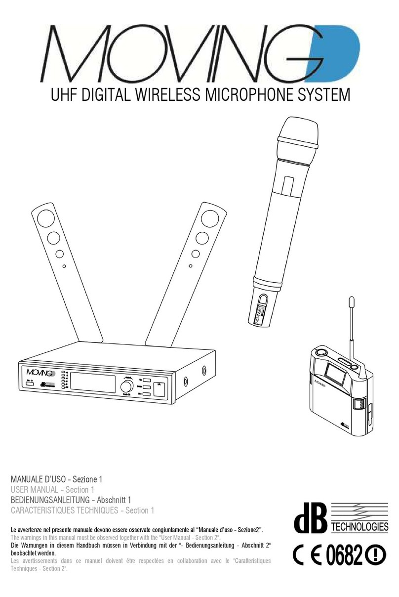
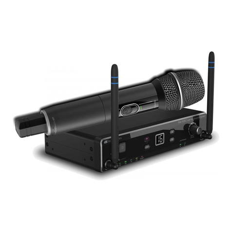
dB Technologies EME ONE User manual

MANUALE D’USO - Sezione 1
USER MANUAL - Section 1
BEDIENUNGSANLEITUNG - Abschnitt 1
CARACTERISTIQUES TECHNIQUES - Section 1
Le vvertenze nel presente m nu le devono essere osserv te congiunt mente l “MANUALE D’USO - Sezione2”.
The w rnings in this m nu l must be observed together with the "USER MANUAL - Section 2".
Die W rnungen in diesem H ndbuch müssen in Verbindung mit der "BEDIENUNGSANLEITUNG - Abschnitt 2" beob chtet werden.
Les vertissements d ns ce m nuel doivent être respectées en coll bor tion vec le "CARATTERISTIQUES TECHNIQUES - Section 2".

EME-ONE Ear Monitor Evolution
1
ITALIANO
Indice
1. INTRODUZIONE.............................................................................................................................................................................1
2. TRASMETTITORE (EME ONE-TX) ............................................................................................................................................2
2.1. Comandi e funzioni .............................................................................................................................................................2
2.2. unzionalità ........................................................................................................................................................................3
3. RICEVITORE (EME ONE-RX) .....................................................................................................................................................4
3.1. Comandi e funzioni .............................................................................................................................................................4
3.2. unzionalità ........................................................................................................................................................................5
3.3. Sostituzione della batteria sul ricevitore ..............................................................................................................................6
4. BANDE E REQUENZE DEL SISTEMA .........................................................................................................................................7
5. SUGGERIMENTI E RACCOMANDAZIONI .....................................................................................................................................7
6. AVVERTENZE ................................................................................................................................................................................8
7. DATI TECNICI ................................................................................................................................................................................9
8. CU IE ( IRE ONE) ..................................................................................................................................................................... 10
8.1. Dati tecnici ........................................................................................................................................................................ 10
A. COLLEGAMENTI – CONNECTIONS - ANSCHLÜSSE - BRANCHEMENTS ............................................................................... 41
B. ESEMPIO DI CON IGURAZIONI / SAMPLE CON IGURATIONS / BEISPIELKON IGURATIONEN / EXEMPLES DE
CON IGURATION ....................................................................................................................................................................... 43
1. INTRODUZIONE
In tutto il mondo la banda radio UHF è estremamente affollata per il suo utilizzo da parte di tutti i
microfoni wireless e IEM (In Ear Monitor), in quanto le stesse frequenze vengono condivise con la
televisione digitale.
Per gli utenti è molto difficile trovare frequenze libere nella banda UHF ed è ancora più difficile
utilizzare queste frequenze su un palco: con EME ONE si è giunti ad un punto di svolta
utilizzando la banda VHF al posto di quella UHF.
La banda VHF è ancora oggi priva di interferenze rispetto alla banda UHF; questo consente di
utilizzare EME ONE su un palco in modo multicanale insieme ad altri sistemi UHF, senza alcuna
interferenza o conflitto con microfoni wireless standard.
EME ONE implementa un innovativo Digital Code Squelch che trasmette informazioni codificate
simultaneamente al segnale audio.
Per completare l'EME ONE è stata inclusa una cuffia personalizzata di produzione Beyerdynamic,
denominata "Fire One" con una definizione incredibile e un impressionante livello di pressione
sonora.
In conclusione il sistema EME-ONE è la r-Evolution in banda VHF:
DEFINITIVAMENTE libero da interferenze della TV digitale
PIU’ FREQUENZE libere per i radiomicrofoni sul palco
CODE SQUELCH per il funzionamento silenzioso in tutte le condizioni
RISPETTO del regolamento mondiale sulle trasmissioni
Il sistema EME ONE è composto da:
- Trasmettitore da tavolo EME ONE-TX alloggiato in un contenitore in ABS ad alta resistenza
e dotato di una antenna telescopica
- Ricevitore pocket EME ONE-RX alloggiato in un contenitore in ABS ad alta resistenza con
antenna flessibile incorporata
- Cuffia personalizzata FIRE ONE Beyerdynamic composta da:
- n°3 gommini di ricambio (taglia S/M/L)
- n°1 paio di “memory foam” – eartips
- n°1 custodia semi-rigida
- Alimentatore full-range 100-240Vac 50/60Hz con uscita 12Vdc con adattatore presa EU e
US
- Pila 9Volts alcalina 6LR61
- Manuale d’uso

ITALIANO
2
2. TRASMETTITORE (EME ONE-TX)
Il trasmettitore del sistema EME-ONE ha 8 canali e funziona
nella banda VHF.
E’ possibile selezionare la frequenza di lavoro del
trasmettitore tramite un commutatore a 8 posizioni posto sul
frontale. L’ antenna alloggiata sul frontale deve essere
estratta per tutta la sua lunghezza durante
l’utilizzo.
ATTENZIONE
Il trasmettitore e il ricevitore devono lavorare sullo stesso canale e banda.
Il cambio del canale può avvenire in ogni momento con trasmettitore accesso o spento.
2.1. Comandi e funzioni
Frontale
1) INTERRUTTORE “POWER”
Permette l’accensione e lo spegnimento del trasmettitore.
2) INDICATORE LUMINOSO "POWER”
E’ utilizzato per segnalare due diverse modalità di funzionamento
VERDE: funzionamento normale
ROSSO: cambio di canale in corso
3) SELETTORE ROTATIVO a 8 posizioni “CHANNELS”
Permette di selezionare il canale da utilizzare (“0” frequenza più bassa - “7” frequenza più
alta)
4) CONTROLLI SENSIBILITA’ INGRESSI “INPUT 1” e “INPUT 2”
Regolano le sensibilità dei segnali agli ingressi “INPUT 1” e “INPUT 2” del trasmettitore.
Questi controlli non influiscono sul livello delle uscite “LINK”.
Con la manopola orientata a sinistra si predispone il trasmettitore a ricevere in ingresso un
segnale a livello “linea”; orientata a destra un segnale a livello “microfonico”.
5) INDICATORE LUMINOSO “PEAK”
Segnala le diverse modalità di funzionamento del corrispondente ingresso.
SPENTO: nessun segnale in ingresso o livello audio molto basso
VERDE: presenza di segnale in ingresso con livello audio normale
GIALLO: presenza di segnale in ingresso con livello audio alto
ROSSO: presenza di segnale in ingresso con livello audio molto alto (picco).
L’indicatore si illumina di colore rosso per segnalare l'intervento del circuito
limitatore interno, il quale evita la distorsione del trasmettitore e protegge il
ricevitore dai sovraccarichi.
Evitare di utilizzare il sistema per lunghi periodi di tempo con l’indicatore
luminoso acceso fisso o lampeggiante.
6) ANTENNA
E’ telescopica e consente la trasmissione del segnale.

EME-ONE Ear Monitor Evolution
3
ITALIANO
Posteriore
1) CONNETTORI DI INGRESSO "INPUT 1” e “INPUT 2”
Ingresso bilanciato/sbilanciato a livello linea (0 dBu).
La presa “COMBO” accetta prese XLR maschio 3 poli e una presa Jack maschio 6,3mm-
1/4”.
2) CONNETTORI DI USCITA "LINK 1” e “LINK 2”
Ogni connettore XLR maschio a 3 poli è connesso in parallelo con gli ingressi corrispondenti
(INPUT 1 e INPUT 2) e può essere utilizzato per inviare il segnale audio all’ingresso di
un'altra apparecchiatura.
3) CONNETTORE ALIMENTAZIONE “DC MAIN INPUT”
Consente di alimentare il ricevitore tramite l’alimentatore 12Vdc in dotazione.
2.2. Funzionalità
Accensione
Premere l’interruttore “POWER” posto sul frontale del trasmettitore.
Il dispositivo eseguirà una rapida sequenza di verifica; in questa fase tutti i led lampeggiano.
La trasmissione sarà attiva appena il led “POWER” resterà acceso Verde fisso.
Selezione del canale
Per cambiare il canale ruotare la manopola “CHANNELS”.
Il cambio del canale avverrà 0,5sec. dopo che la manopola sarà stata ruotata. Durante il processo
di cambio canale il led “POWER” diventerà di colore Rosso.
Terminata la procedura il led torna di colore Verde e la trasmissione sul nuovo canale sarà attiva.
ATTENZIONE
Non selezionare più trasmettitori per ogni frequenza di banda per evitare interferenze di
trasmissione.
Regolazione del volume
Il dispositivo accetta in ingresso sia segnali di tipo linea (LINE) che
microfonico (MIC).
La regolazione del volume è stata suddivisa per la metà a sinistra per
l’utilizzo di segnali a livello linea ed a destra per segnali a livello
microfonico.
Al fine di ottenere un livello audio ottimale, senza distorsioni, si
suggerisce di regolare il volume in modo che l’indicatore luminoso
“PEAK” corrispondente all’ingresso relativo non sia mai accesso fisso, ma solo per brevi istanti.
ATTENZIONE
Nel caso in cui il volume sia regolato tutto al minimo e il led “PEAK” rimanga rosso,
verificare il livello di ingresso del dispositivo collegato (mixer, sequencer digitali, …):
potrebbe essere troppo alto e dovrà essere abbassato.
Antenna
Per un corretto funzionamento, l’antenna deve essere completamente estesa ed orientata verso
l’alto. Non coprire mai l’antenna durante l’utilizzo.

ITALIANO
4
Utilizzo ottimale del trasmettitore
Il trasmettitore del sistema EME-ONE incorpora un mixer audio a due canali con la possibilità di
miscelarli tra loro. La qualità di ricezione dipende anche dai livelli di segnale che si applicano
all’ingresso del trasmettitore.
Per questo è consigliabile seguire le seguenti semplici regole:
1. Regolare le manopole dei due ingressi audio al minimo
2. Regolare il segnale di uscita del mixer o altro strumento collegato per il massimo livello
possibile
3. Regolare l’ingresso utilizzato per l’EME-ONE fino a veder lampeggiare solo nei picchi gli
indicatori luminosi “PEAK” e lasciare al minimo l’ingresso non utilizzato (tutto ruotato in
senso antiorario)
4. Accendere il ricevitore sul canale corrispondente e regolare il volume audio al livello
desiderato
La procedura sopra descritta vale per tutti gli strumenti collegati all’ingresso del trasmettitore.
Collegamenti
Fare riferimento alla sezione dedicata nel manuale
3. RICEVITORE (EME ONE-RX)
Il ricevitore del sistema EME-ONE ha 8 canali radio, più due canali che
funzionano da monitor disattivando la ricezione radio.
E’ possibile selezionare la frequenza di lavoro del ricevitore tramite il
commutatore a 10 posizioni posto nel retro del ricevitore.
E’ dotato di una molla per il fissaggio a cintura.
ATTENZIONE
Il trasmettitore e il ricevitore devono lavorare sullo stesso canale e
banda.
Il cambio del canale può avvenire in ogni momento sia con
ricevitore accesso oppure spento.
3.1. Comandi e funzioni

EME-ONE Ear Monitor Evolution
5
ITALIANO
1) MANOPOLA ACCENSIONE E CONTROLLO VOLUME “VOLUME”
Ha una doppia funzione sia di accensione/spegnimento del ricevitore, manopola ruotata
completamene a sinistra, che di controllo volume in progressione da sinistra a destra.
2) INDICATORE LUMINOSO "POWER”
E’ utilizzato per segnalare le diverse modalità di funzionamento
SPENTO: ricevitore spento
VERDE: ricevitore acceso e batteria carica
ROSSO: ricevitore acceso e batteria scarica
3) INDICATORE LUMINOSO "RF/PEAK”
E’ utilizzato per segnalare le diverse modalità di funzionamento
SPENTO: nessun segnale RF rilevato e canale /frequenza liberi (se
l’indicatore luminoso “POWER” (2) è acceso)
VERDE LAMPEGGIANTE: canale/frequenza occupati da un altro sistema o disturbo
VERDE: comunicazione RF presente e riconosciuta
ROSSO LAMPEGGIANTE: presenza di segnale con livello audio molto alto del
trasmettitore (picco)
4) CONNETTORE DI USCITA “AUDIO OUT”
Questo connettore serve per il collegamento della cuffia fornita in dotazione.
Utilizzare un connettore Jack stereo 3,5mm
5) CONNETTORE DI INGRESSO “AUX”
E’ in grado di accettare prese Jack male 6,3mm – 1/4” sia mono che stereo (con Phantom
Power).
Tramite questo ingresso è possibile ascoltare in cuffia la sorgente audio collegata al
connettore “AUX” in contemporanea/sovrapposto al segnale audio inviato dal trasmettitore.
6) INTERRUTTORE ATTENUAZIONE INGRESSO “AUX”
Questo interruttore permette di regolare l’attenuazione a 0dB oppure -10dB del segnale in
ingresso “AUX” (5)
7) SELETTORE ROTATIVO a 10 posizioni “CHANNELS”
Questo commutatore rotativo permette di selezionare la frequenza sulla quale ci si vuole
sintonizzare (“0” frequenza più bassa - “7” frequenza più alta); le altre due posizioni
identificate con “GUITAR MONITOR” servono per utilizzare il sistema come monitor
disabilitando lo stadio in radiofrequenza.
8) MOLLA CINTURA
Consente di agganciare il ricevitore a una cintura oppure alla cinghia della chitarra.
9) SPORTELLO BATTERIA
Vano per alloggiamento batteria
10) ANTENNA
Fissa. Consente la trasmissione del segnale.
3.2. Funzionalità
Accensione e regolazione del volume
Ruotare la manopola in senso orario per accendere il ricevitore.
All’accensione si sentirà uno scatto meccanico e il volume
dell’audio è impostato al minimo.
Ruotando la manopola in senso orario il volume aumenta e in
senso antiorario diminuisce.
L’accensione è confermata dal led corrispondente (2).

ITALIANO
6
Selezione del canale
Per cambiare il canale ruotare la manopola posta sul retro del ricevitore.
I due canali indicati come “GUITAR MONITOR” prevedono lo spegnimento dello stadio radio in
modo da ridurre i consumi e consentire una durata maggiore della batteria.
Per l’utilizzo fare riferimento alla sezione delle applicazioni.
ATTENZIONE
Nel caso di utilizzo di più sistemi nella stessa banda, assicurarsi che il ricevitore sia
sintonizzato sullo stesso canale del trasmettitore desiderato.
Antenna
L’antenna è in materiale flessibile per permette un migliore utilizzo. Non coprire mai l’antenna
durante l’utilizzo.
Ingresso ausiliario audio
Con questo ingresso è possibile ascoltare in cuffia una qualunque sorgente audio.
Il segnale viene sempre sovrapposto a quello inviato dal trasmettitore. Il segnale sull’ingresso
ausiliario sarà sempre presente anche in caso di perdita del segnale trasmesso.
Il caso di cambio canale, si avranno alcuni istanti di mute.
L’ingresso dispone di un interruttore, posto sul fianco, che ne può attenuare il volume.
L’alimentazione “Phantom” (5Vdc) è sempre presente sul connettore jack dell’ingresso AUX.
Fare riferimento alla sezione dedicata nel manuale
ATTENZIONE
Inserire il jack degli auricolari nella presa del ricevitore prima di introdurre gli auricolari
nelle orecchie.
Impostare il volume audio al minimo e regolare gradualmente il volume.
L’improvvisa esposizione a rumori intensi può causare danni all’apparato uditivo.
Indicazione batteria scarica
La segnalazione di batteria scarica avviene in due modi:
- Il led “POWER” cambia di colore da Verde a Rosso
- Viene generato un “beep” sull’audio ogni 15sec.
Collegamenti
Fare riferimento alla sezione dedicata nel manuale
AVVERTENZE
- Nel caso di prolungato inutilizzo del ricevitore si consiglia di rimuovere le batterie per
evitare possibili danni dovuti a perdite delle batterie stesse.
- Utilizzare batterie alcaline
- Non utilizzare batterie vecchie
- Assicurarsi che le batterie dei ricevitore siano cariche ed efficienti
- Verificare che sia rispettata la polarità della batteria, seguendo le indicazioni riportare
nel relativo vano
3.3. Sostituzione della batteria sul ricevitore
- Fare una leggera pressione in corrispondenza del vano
dello sportello (Fig. A).
- Aprire completamente lo sportello (Fig. B)
- Inserire o sostituire le batterie nel vano predisposto
prestando particolare attenzione alle polarità indicate sul
fondo +/- (Fig. C)
- Richiudere lo sportello pila assicurandosi che sia
correttamente chiuso (Fig. D)

EME-ONE Ear Monitor Evolution
7
ITALIANO
4. BANDE E FREQUENZE DEL SISTEMA
Importante
Prima di utilizzare questo apparato, contattare le Autorità di Regolamentazione delle
Telecomunicazioni del Paese in uso per avere informazioni sulle frequenze disponibili e sui
requisiti di alimentazione consentiti.
Banda 1
174MHz – 184MHz
Banda 2
194MHz – 204MHz
Banda 3
213MHz – 223MHz
CH0 174.025MHz CH0 194.000 MHz CH0 213.100MHz
CH1 174.725MHz CH1 194.775MHz CH1 213.575MHz
CH2 176.025MHz CH2 196.300MHz CH2 215.100MHz
CH3 177.550MHz CH3 199.125MHz CH3 218.050MHz
CH4 178.625MHz CH4 200.425MHz CH4 218.750MHz
CH5 181.675MHz CH5 200.900MHz CH5 220.525MHz
CH6 183.450MHz CH6 202.975MHz CH6 221.450MHz
CH7 183.925MHz CH7 203.975MHz CH7 222.750MHz
In alcuni paesi l’utilizzo di terminali di telecomunicazione è soggetto alla Licenza d’uso.
Verificare nel paese di utilizzo con le Autorità Locali se tale licenza è obbligatoria.
5. SUGGERIMENTI E RACCOMANDAZIONI
Verificare che ricevitore e trasmettitore abbiano la stessa frequenza di lavoro.
Ogni trasmettitore può funzionare solamente se viene utilizzato con il ricevitore della
stessa banda e sulla stessa frequenza.
ATTENZIONE
Prima di alimentare il trasmettitore assicurarsi che la tensione di rete corrisponda alla tensione
d’ingresso indicata sull’alimentatore.
Il trasmettitore deve essere alimentato solo ed esclusivamente con l’alimentatore fornito in
dotazione.
Alimentare il trasmettitore collegando l’alimentatore al connettore “DC MAIN INPUT” situato nella
parte posteriore del ricevitore.
Problemi di interferenza
Per evitare i problemi d’interferenza:
- mantenere i trasmettitori ad almeno 1/1,5 metri di distanza da OGNI ricevitore
- nel caso in cui il trasmettitore e il ricevitore debbano lavorare a meno di 1m, abbassare
completamente l’antenna del trasmettitore.
- la portata effettiva dipende da eventuali disturbi presenti sul canale selezionato, ostacoli
presenti tra trasmettitore e ricevitori, riflessioni del segnale legate all’ambiente di
utilizzo.
Utilizzo simultaneo di più sistemi
L’EME-ONE è adatto all'utilizzo simultaneo di più sistemi (4 per ogni banda).
Si consiglia di mantenere un intervallo di almeno 1 canale (0,2,4,6) oppure (1,3,5,7).
In caso di problemi durante l’utilizzo contemporaneo di diversi sistemi, controllare le frequenze in
uso, in particolare evitare conflitti di frequenza (controllare i canali di trasmissione)

ITALIANO
8
In caso d’ interferenza:
- spegnere tutti i trasmettitori e verificare se il led “RF/PEAK” e lampeggia di colore
Verde; questo accorgimento consente di identificare una possibile sorgente diretta di
interferenza esterna
- accendere un trasmettitore alla volta e verificare che solo il ricevitore corrispondente si
sincronizzi verificando che il led “RF/PEAK” sia di colore Verde fisso.
Lo stesso criterio, per la scelta della frequenza, deve essere applicato anche se si utilizza il
sistema EME-ONE insieme ad altri radiomicrofoni
6. AVVERTENZE
Effetto “LARSEN”
L’effetto Larsen (detto anche “feedback” acustico) è un suono fastidioso che si genera quando
microfoni troppo vicini ed orientati verso i diffusori acustici che emettono i suoni captati dai
microfoni stessi. Per evitare l’effetto “Larsen” (che può danneggiare gli altoparlanti), si
raccomanda di mantenere una certa distanza tra i microfoni ed i diffusori acustici, abbassare il
volume dei microfoni (se necessario) e non puntarli verso i diffusori acustici.
Fenomeni induttivi
Per evitare che fenomeni induttivi diano luogo a ronzii e disturbi che compromettono il buon
funzionamento del sistema evitare di porre i trasmettitori e i ricevitori in prossimità di
apparecchiature che inducono forti campi magnetici (es. trasformatori di alimentazione, conduttori
di energia elettrica e linee che alimentano i diffusori)
Perdite di segnale (drop outs)
Ci sono zone in cui è difficile ricevere correttamente il segnale. Per evitare perdite di segnale
occorre spostare il trasmettitore in una posizione più appropriata, evitare di interporre ostacoli e,
eventualmente, ridurre la distanza tra trasmettitore e ricevitore.
Posizionare il trasmettitore più lontano possibile alla sorgente del disturbo per evitare rumori
esterni o suoni indesiderati.
Livelli di volume
La presente apparecchiatura è in grado di produrre elevati livelli di intensità sonora
negli auricolari. Si prega di volere prendere atto di questa possibilità e di tenere il
volume più basso possibile.
Inoltre ricordare:
LIVELLI DI VOLUME ECCESSIVAMENTE ALTI POSSONO PROVOCARE DANNI
PERMANENTI ALL’UDITO
I limitatori incorporati nel sistema sono progettati in modo da poter controllare le variazioni
improvvise di livello; NON sono progettati per poter fungere da protezioni a lungo termine per
l’udito.
Sottoponete periodicamente le vostre orecchie al controllo di uno specialista in audiologia. Se, in
qualsiasi momento, sentite una irritazione o vi si forma del cerume, INTERROMPETE
IMMEDIATAMENTE L’USO e fate controllare quanto prima le vostre orecchie.

EME-ONE Ear Monitor Evolution
9
ITALIANO
7. DATI TECNICI
TRASMETTITORE
Dimensione Mezza unità rack
Sensibilità ingresso audio Regolabile da 50mv a 5V RMS
Alimentazione 12Vdc 500mA
Consumo di corrente 250mA
Ingresso audio
0dBm/
5
K
oh
m
Linea bilanciata/sbilanciata
Risposta in frequenza 40Hz to 16KHz ~ 3dB
Distorsione <1% a deviazione nominale
requenze operative 3 bande – 8 canali
Modulazione M con Digital Code Squelch
Deviazione 35KHz nom. @ 1KHz sinusoidale
Compander Quadratico
Antenna 1 integrata
Range di temperatura -10°C/+50°C
Stabiltà in frequenza -10°C/+45°C
Peso 200gr.
RICEVITORE
Alimentazione 9V alcalina (6LR61)
Risposta in frequenza 40Hz to 16KHz ~ 3dB
Distorsione <1% a deviazione nominale
Sensibilità -90dBm
Consumo di corrente ~60mA a 9V – volume medio
requenze operative
3 bande
–
8
canali
2 canali monitor
Espansore di dinamica Quadratico
Antenna 1 integrata
Range di temperatura -10°C/+50°C
Stabiltà in frequenza -10°C/+45°C
Limiter Si
Avviso batteria scarica Si
Durata batteria >6 ore
Peso 150gr (con pila)

ITALIANO
10
SISTEMA
Tipo di ricevitore Monoantenna / 8 canali
Risposta in frequenza da 40Hz a 16KHz ~ 3dB
Distorsione THD <1% a deviazione nominale
Rapporto S/N 104dB pesato “A”
Modulazione
3E (modulazione di frequenza)
Deviazione 35KHz nom. @ 1KHz sinusoidale
Conformità alla direttiva 1995/5/CE
Portata massima di lavoro*
40metri (indoor)
100metri (outdoor)
Peso netto (con alimentatore) 800gr
* Il dato è indicativo e la portata dipende sia del setup che dal luogo di utilizzo.
La portata può essere notevolmente ridotta in presenza di ostacoli e strutture in metallo e/o cemento armato.
8. CUFFIE (FIRE ONE)
Il sistema EME ONE viene completato con una cuffia personalizzata di produzione Beyerdynamic
denominata "FIRE ONE".
Questi auricolari offrono un’eccellente qualità di suono su tutta la banda audio. Sono dotati di
driver acustici al Neodimio e supporti metallici leggeri che rendono queste cuffie versatili e di
ottima qualità.
Vengono forniti in dotazione agli auricolari:
- n°3 gommini di ricambio (taglia S/M/L)
- n°1 paio di “memory foam” – eartips
- n°1 custodia semi-rigida
8.1. Dati tecnici
Tipo di trasduttore Dinamico
Risposta in frequenza 20 – 22,000 Hz
Impedenza nominale 12Ohm
Sensibilità 104dB
Lunghezza cavo 1,2m
Connettore mini stereo jack plug (3,5mm)

EME-ONE Ear Monitor Evolution
ENGLISH
11
Index
1. INTRODUCTION .......................................................................................................................................................................... 11
2. TRANSMITTER (EME ONE-TX) ............................................................................................................................................... 12
2.1. CONTROLS AND UNCTIONS ....................................................................................................................................... 12
2.2. unctions .......................................................................................................................................................................... 13
3. RECEIVER (EME ONE-RX) .......................................................................................................................................................... 14
3.1. Controls and functions ...................................................................................................................................................... 14
3.2. unctions .......................................................................................................................................................................... 15
3.3. Replacing the battery on the receiver ............................................................................................................................... 16
4. SYSTEM BANDS AND REQUENCIES ....................................................................................................................................... 17
5. SUGGESTIONS AND RECOMMENDATIONS ............................................................................................................................. 17
6. CAUTIONS ................................................................................................................................................................................... 18
7. TECHNICAL SPECI ICATION ..................................................................................................................................................... 19
8. HEADPHONES ( IRE ONE) ......................................................................................................................................................... 20
8.1. Technical specification ..................................................................................................................................................... 20
A. COLLEGAMENTI – CONNECTIONS - ANSCHLÜSSE - BRANCHEMENTS
........................................................
41
B. ESEMPIO DI CON IGURAZIONI / SAMPLE CON IGURATIONS / BEISPIELKON IGURATIONEN / EXEMPLES DE
CON IGURATION
.........................................................................................................................
43
1. INTRODUCTION
All over the world the UHF radio band is extremely crowded, as far as its use by all wireless and
IEM (In Ear Monitor) microphones is concerned, as the same frequencies are shared with the
digital TV.
Users have great difficulties to find any free frequencies in the UHF band, and using these
frequencies on a stage is even more difficult: EME ONE is a true turning point in this field, as it
uses the VHF band instead of the UHF one.
The VHF band is still interference-free compared to the UHF band; this allows to use EME ONE
on a stage in multi-channel mode with other UHF systems, without any interference or conflict with
standard wireless microphones.
EME ONE implements an innovative Digital Code Squelch, which transmits encoded information
along with the audio signal.
EME ONE also includes a custom headphone from Beyerdynamic, "Fire One", featuring incredible
resolution and an impressive sound pressure level.
In conclusion, the EME-ONE system is the r-Evolution in the VHF BAND:
FOREVER free from digital TV interferences
MORE FREQUENCIES free for radio microphones on the stage
CODE SQUELCH for noise-free operation under any condition
COMPLIANCE with world regulations on transmissions
The EME ONE system consists of:
- Tabletop transmitter EME ONE-TX, housed in a high-resistance ABS box and equipped with
a telescopic antenna
- Pocket receiver EME ONE-RX, housed in a high-resistance ABS box and equipped with a
built-in flexible antenna
- Custom headset FIRE ONE from Beyerdynamic, consisting of:
- 3 spare rubber pieces (size S/M/L)
- 1 pair of “memory foam” – ear tips
- 1 semi-rigid casing
- Full-range 100-240Vac 50/60Hz power supply with 12Vdc output and EU/US outlet adapter
- 9Volt alkaline battery 6LR61
- Operating manual

ENGLISH
12
2. TRANSMITTER (EME ONE-TX)
The EME-ONE system transmitter has 8 channels and
operates in the VHF band.
The transmitter operating frequency can be selected by
means of an 8-position switch located on the transmitter
front panel. The antenna housed in the front panel must
be fully extended during use.
ATTENTION
The transmitter and the receiver must operate in the same channel and band.
The channel can be switched at any time, with the transmitter on or off.
2.1. CONTROLS AND FUNCTIONS
Front
1) “POWER” SWITCH
It allows to power the transmitter on and off.
2) “POWER” INDICATOR LIGHT
It is used to indicate two different operating modes
GREEN: normal operation
RED: channel switching under way
3) 8-position “CHANNELS” ROTARY SWITCH
It allows to select the desired tune-in channel (“0” lowest frequency - “7” highest frequency)
4) “INPUT 1” and “INPUT 2” SENSITIVITY CONTROL
It adjusts the sensitivity of the transmitter input signal, for the corresponding input.
This control doesn't affect the “LINK” output level
The knob controls both the microphone and line signal levels. Use the left knob for line-level
signals and the right one for microphone-level signals.
5) “PEAK” INDICATOR LIGHT
It is used to indicate the different operating modes of the corresponding input.
OFF: no input signal or audio level very low
GREEN: input signal present and audio level normal
YELLOW: input signal present and audio level high
RED: input signal present and audio level very high (peak)
The indicator glows red to signal the tripping of the internal limiting circuit,
preventing transmitter distortion and protecting the receiver against
overloads.
Avoid using the system for prolonged time with the indicator light steadily on
or flashing.
6) ANTENNA
The telescopic antenna allows signal transmission.

EME-ONE Ear Monitor Evolution
ENGLISH
13
Rear
1) “INPUT 1” and “INPUT 2” INPUT CONNECTOR
Balanced/unbalanced input at line level (0 dBu).
The “COMBO” socket can accept 3-pole XLR male socket and a 6.3mm-1/4” male Jack
socket.
2) "LINK 1” and “LINK 2” OUTPUT CONNECTOR
The 3-pole male XLR connector is connected in parallel with the corresponding inputs
(INPUT 1 and INPUT 2) and can be used to send the input audio signal to an other
equipment.
3) “DC MAIN INPUT” POWER CONNECTOR
It allows to power the receiver through the 12Vdc power supply accompanying the unit.
2.2. Functions
Power on
Press the “POWER” switch located on the front panel of the transmitter.
The equipment will perform a quick check sequence; during this stage all LEDs flash.
Transmission will be active as soon as the “POWER” LED steadily glows green.
Channel selection
To switch the channel turn the “CHANNELS” knob.
The channel will be switched 0.5sec. after the knob has been turned. During the channel
switching process the “POWER” LED turns to red.
Once the procedure is completed the LED turns back to green and the transmission on the new
channel will be active.
WARNING Never select more than one transmitter for each band frequency to avoid
transmission interferences.
Adjusting the volume
The device accepts both line (LINE) and microphone (MIC) input
signals.
Volume adjustment has been split into two halves; the left one for line
signals and the right one for microphone signals.
To achieve an optimum, distortion-free audio level, we recommend that
you adjust volume to a level ensuring that the “PEAK” indicator light
corresponding to the relevant input is never steadily on, unless for a few moments.
ATTENTION
Should the volume be set to the lowest level and should the “PEAK” LED keep glowing
red, check the input level of the connected device (mixer, digital sequencers, …) as it
might be too high and it will have to be lowered.
Antenna
For proper operation, the antenna must be fully extended and oriented upward.
Never cover the antenna when the unit is in use.

ENGLISH
14
Optimum transmitter usage
The EME-ONE system transmitter has a built-in two-channel audio mixer, allowing cross-mixing.
The quality of reception also depends on the signal levels applied to the transmitter input.
For this reason you should observe the following simple rules:
5. Set the knobs of the two audio inputs to the minimum level
6. Set the output signal of the mixer or of any other connected instrument to the highest
possible level
7. Adjust the input used for EME-ONE until the “PEAK” indicator lights only flash at peak time
and leave the unused input at the lowest possible level (fully turned anti-clockwise)
8. Switch on the receiver on the corresponding channel and set the audio volume to the desired
level
The procedure described above applies to all the instruments connected to the transmitter input.
Connections
Please refer to the relevant section in the manual
3. RECEIVER (EME ONE-RX)
The EME-ONE system receiver has 8 radio channels, plus two channels
serving as monitors by disabling radio reception.
The receiver operating frequency can be selected by means of a 10-position
switch located on the receiver rear panel.
It is equipped with a spring for belt clipping.
ATTENTION
The transmitter and the receiver must operate in the same channel
and band.
The channel can be switched at any time, with the receiver on or off.
3.1. Controls and functions

EME-ONE Ear Monitor Evolution
ENGLISH
15
1) POWER-ON AND VOLUME CONTROL KNOB “VOLUME”
This knob has a double function: it allows to power the receiver on/off, when it is fully turned
to the left, and to control volume, when turned from left to right.
2) “POWER” INDICATOR LIGHT
It is used to indicate different operating modes
OFF: receiver off
GREEN: receiver on and battery charged
RED: receiver on and battery depleted
3) “RF/PEAK” INDICATOR LIGHT
It is used to indicate different operating modes
OFF: no RF signal detected and channel/frequency free (if the “POWER”
(2) indicator light is on)
GREEN, FLASHING: channel/frequency occupied by another system or noise
GREEN: RF communication established and recognized
RED, FLASHING: presence of signal with a very high (peak) transmitter audio level
4) 'AUDIO OUT' OUTPUT CONNECTOR
The supplied headphones have to be connected to this connector.
Use a 3.5mm stereo Jack connector
5) "AUX" INPUT CONNECTOR
It can accept both mono and stereo 6.3mm – 1/4” male jack sockets (with Phantom Power).
This input allows to listen to the connected audio source through the headphones,
simultaneously/overlapped with the audio signal sent by the transmitter.
6) “AUX” INPUT ATTENUATION SWITCH
This switch allows to select the 0dB or -10dB attenuation of the “AUX” input signal (5)
7) 10-position “CHANNELS” ROTARY SWITCH
This rotary switch allows to select the desired tune-in frequency (“0” lowest frequency - “7”
highest frequency); the other two positions, marked with “GUITAR MONITOR”, allow to use
the system as a monitor, disabling the radiofrequency stage.
8) BELT SPRING
It allows to clip the receiver to a belt or to the guitar strap.
9) BATTERY COVER
Battery housing compartment
10) ANTENNA
The antenna allows signal transmission.
3.2. Functions
Power-on and volume adjustment
Turn the knob clockwise to power on the receiver. At power on
you the unit will click and audio volume will be set to the lowest
level.
Turn the knob clockwise to increase the volume and anti-
clockwise to decrease it.
Power-on is confirmed by the corresponding LED (2).

ENGLISH
16
Channel selection
To switch the channel turn the knob located on the receiver rear panel.
The two channels marked as “GUITAR MONITOR” cause the radio stage to we switched off, to
reduce consumptions and prolong the battery life.
For information about their use please refer to the application section.
ATTENTION
Should multiple systems be used in the same band, make sure that the receiver is tuned
in to the same channel as that of the desired transmitter.
Antenna
The antenna is made of a flexible material, for better use. Never cover the antenna when the unit
is in use.
Auxiliary audio input
This input allows to listen to any audio source through the headphones.
The signal always overlaps with the one sent by the transmitter. The signal on the auxiliary input
will always be present, even in case the transmitted signal should drop out.
In case of channel switching, audio will be mute for a few moments.
The input is equipped with a side switch, allowing to attenuate its volume.
The “phantom” power supply (5Vdc) is always present on the jack connector of the AUX input.
Please refer to the relevant section in the manual
ATTENTION
Insert the earpiece jack into the receiver socket before inserting the earpieces into your
ears.
Set the audio volume to the lowest level and gradually adjust the volume.
Sudden exposure to high-volume noises may damage your hearing system.
Depleted battery indication
Battery depletion is signaled by two events:
- The “POWER” LED turns from green to red
- A “beep” overlapping the audio is generated every 15sec.
Connections
Please refer to the relevant section in the manual
CAUTIONS
- Should the receiver remain unused for a prolonged time we recommend that you
remove the batteries to prevent possible damages due to leaks from the batteries.
- Use alkaline batteries
- Never use old batteries
- Make sure the receiver batteries are charged and in good working order
- Check that battery polarity complies with the indications found in the relevant
compartment
3.3. Replacing the battery on the receiver
- Slightly press the cover compartment (Fig. A).
- Fully open the cover (Fig. B)
- Insert or replace the batteries in the relevant
compartment, paying special attention to the +/- polarities
specified on the bottom (Fig. C)
- Close the battery cover, paying special attention to
ensure that it is properly closed (Fig. D)

EME-ONE Ear Monitor Evolution
ENGLISH
17
4. SYSTEM BANDS AND FREQUENCIES
Important
Before using this equipment, please contact the Telecommunication Regulation Authorities of the
country where the system is in use for information about the available frequencies and the power
supply requirements .
Band 1
174MHz – 184MHz
Band 2
194MHz – 204MHz
Band 3
213MHz – 223MHz
CH0 174.025MHz CH0 194.000 MHz CH0 213.100MHz
CH1 174.725MHz CH1 194.775MHz CH1 213.575MHz
CH2 176.025MHz CH2 196.300MHz CH2 215.100MHz
CH3 177.550MHz CH3 199.125MHz CH3 218.050MHz
CH4 178.625MHz CH4 200.425MHz CH4 218.750MHz
CH5 181.675MHz CH5 200.900MHz CH5 220.525MHz
CH6 183.450MHz CH6 202.975MHz CH6 221.450MHz
CH7 183.925MHz CH7 203.975MHz CH7 222.750MHz
In some countries the use of telecommunication terminals is subject to a license.
Please check with local authorities in the country where the system is in use to verify whether the
license in question is mandatory.
5. SUGGESTIONS AND RECOMMENDATIONS
Check that receiver and transmitter have the same operating frequency.
Any transmitter can only work if it is used with the receiver operating in the same band
and frequency.
ATTENTION
Before powering the transmitter make sure that the mains voltage matches the input voltage
specified on the power supply.
The transmitter must only be powered using the supplied power supply.
Power the transmitter by connecting the power supply to the “DC MAIN INPUT” connector located
on the rear of the receiver.
Interference problems
To avoid interference problems:
- keep the transmitters at least 1/1.5 metres away from ANY receiver
- should the transmitter and the receiver have to operate at less than 1m from each other,
fully lower the transmitter antenna.
- the effective range depends on the presence of any noise on the selected channel, of
obstacles between transmitter and receiver or of signal reflections linked to the usage
environment.
Simultaneous use of multiple systems
EME-ONE is suitable for the simultaneous use of multiple systems (4 for each band).
We recommend that you leave at least a 1-channel gap (0,2,4,6) or (1,3,5,7).
In case of trouble while simultaneously using different systems, check the frequencies in use; in
particular, avoid frequency conflicts (check the transmission channels)

ENGLISH
18
In case of interference:
- power off all transmitters and check whether the “RF/PEAK” LED is blinking and glows
green. This allows to identify a possible direct source of external interference
- power on a transmitter at a time and check that only the corresponding receiver gets
synced, verifying that the “RF/PEAK” LED glows green and is steadily on.
The same radiofrequency choice criteria also apply if using the EME-ONE system along with other
radio microphones
6. CAUTIONS
“LARSEN” effect
The Larsen effect (also known as audio feedback) is an annoying sound generated when there
are any microphones which are too close to each other and are oriented toward the audio
speakers emitting the sounds picked by the microphones themselves. To avoid the Larsen effect
(which may damage the loudspeakers), we recommend that you leave a certain distance between
the microphones and the audio speakers; also lower the microphone volume (if needed) and don't
aim them at the audio speakers.
Induction-related phenomena
To prevent induction-related phenomena from generating buzzes and noise which compromise
proper system operation avoid placing the transmitters and receivers near equipment inducing
strong magnetic fields (e.g. power transformers, power conductors and lines powering the
speakers)
Drop outs
There area areas in which proper signal reception is difficult. To avoid drop outs you need to
move the transmitter to a more appropriate location, avoid interposing any obstacles and, if
needed, reduce the distance between transmitter and receiver.
Place the transmitter as far away as possible from the source of the disturbance, to avoid external
noises or unwanted sounds.
Volume levels
This equipment can generate high-intensity sounds in earpieces. Please take this
into account and keep volume as low as possible.
Please also remember:
TOO HIGH VOLUME LEVELS MAY RESULT IN PERMANENT DAMAGES TO HEARING
The limiters built into the system are designed to be able to control sudden level fluctuations; they
are NOT designed to serve as long-term hearing protections.
Periodically have a specialised audiologist check your ears. Should you experience any irritation
or earwax formation, IMMEDIATELY STOP USING THE EQUIPMENT and have your ears
checked as soon as possible.

EME-ONE Ear Monitor Evolution
ENGLISH
19
7. TECHNICAL SPECIFICATION
TRANSMITTER
Receiver size Half rack size
Audio input sensitivity Adjustable from 50mv to 5V RMS
Power supply 12Vdc 500mA
Current consumption 250mA
Audio input
0dBm/5Kohm
Balanced/Unbalanced line
requency response 40Hz to 16KHz ~ 3dB
Distortion <1% at nominal deviation
Operating frequency 3 bands – 8 channels
Modulation M with Digital Code Squelch
Deviation 35KHz nom. @ 1KHz sinusoidal
Compander Quadratic
Antenna 1 integrated
Temperature range -10°C/+50°C
requency stability -10°C/+45°C
Weight 200gr.
RICEIVER
Power supply 9V alkaline (6LR61)
requency response 40Hz to 16KHz ~ 3dB
Distortion <1% at nominal deviation
Sensitivity -90dBm
Current consumption ~60mA at 9V – medium volume
Operating frequency
3 bands
–
8 channels
2 channels monitor
Compander Quadratic
Antenna 1 integrate
Temperature range -10°C/+50°C
requency stability -10°C/+45°C
Limiter Yes
lat battery warning Yes
Battery life >6 hours
Weight 150gr (with battery)
Table of contents
Languages:
Other dB Technologies Microphone System manuals
Popular Microphone System manuals by other brands

Reloop
Reloop RWM-10 HH Operation manual

Audio Technica
Audio Technica ATCS-60 instruction manual

ASO Safety Solutions
ASO Safety Solutions ELMON Inductive 71-242 operating manual

ATCOM
ATCOM AT800DP user manual

ASO Safety Solutions
ASO Safety Solutions ELMON wicom 85-463 quick guide

Better Music Builder
Better Music Builder VM-93C G5 operating manual