DCS Proto-Sound 2.0 Diesel/Electric Locomotive Upgrade... User manual

DIESEL/ELECTRIC
LOCOMOTIVE UPGRADE KIT
INSTALLATION MANUAL
2nd Edition
Compatibility
This Proto-Sound 2.0 Diesel/Electric Locomotive Upgrade Kit is compatible with any AC
or DC Powered locomotive equipped with a DC can motor(s) and motor flywheel(s). The
locomotive must be large enough to house the electronics. The instructions herein are
generic in nature and will not provide the installer with specific installation details for
specific locomotives. Consult the individual item’s operator’s manual for specific
instructions on how to disassemble the locomotive prior to installing the upgrade kit.
This product is not covered by a warranty unless installed by an M.T.H.
Authorized Conversion Center.
WARNING:
PLEASE READ BEFORE USE AND SAVE FOR REFERENCE

Table of Contents
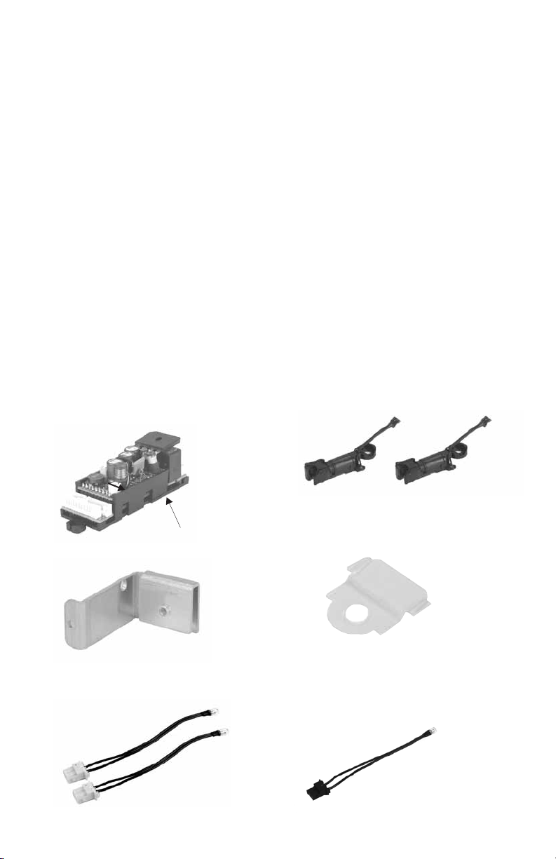
Contents Of The Kit.
Upgrading Multiple-Unit Diesels
Locomotive Inspection & Review
Preparing The Chassis For the Upgrade
Installing The PS-2 Components Onto the Chassis
Testing The PS-2 Installation
Loading Proto-Sound 2.0 Files Into Locomotive
Proto-Sound 2.0 Operation Instructions
...........................................................................................
Required Tools......................................................................................................
........................................................ .............
......................................................................
.........................................
Mounting The PS-2 Board....................................................................
Installing The Proto-Couplers...............................................................
PS-2 Chassis Wiring Diagram...............................................................
Installing The Chassis Harness.............................................................
Soldering Speaker Connections............................................................
Connecting Motor, Ground & Pickup Wires
Connecting Lights
Connecting Smoke Unit To The Harness..............................................
Wire Management/Short Circuit Prevention.........................................
..............................................................................
..............................................
...........................................................
Conventional Operation .......................................................................
Warranty Coverage & Service Options.................................................
Limited 90-Day Warranty......................................................................
.
..
...........................................................
Installing The Battery, Recharging Jack & Volume Pot........................
Installing The Tach Reader Bracket......................................................
Installing The Flywheel Tach Tape........................................................
Mounting The Tach Reader To The Tach Bracket.................................
.........................................
.................................................................................
Self-Recharging Battery........................................................................
Troubleshooting....................................................................................
............................................................................
......................................................................
Coupler Insulator Installation
Service & Warranty Information
42
43
43
43
WARNING: This product is not covered by a warranty unless installed by an
M.T.H. Authorized Conversion Center.
18
19
20
22
22
23
24
24
26
27
28
29
32
32
38
39
3
7
8
9
10
11
12
15
16

Contents Of The Kit
A) PS-2 Board and Plastic Bracket
AA) PS-2 Heat Sink Bracket
B) Mars Light (2)
C) Proto-Coupler (2)
D) Backup Light
E) Marker Lights- Red
EE) Marker Lights- Green
F) 7-Pin Pickup Harness w/Tach Reader
FF) Tach Reader Bracket
FFF) Tach Tape
G) Headlight
H) Speaker
I) AA Ni-Cd battery pack
(Charge before use)
II) Battery Charging Jack
CC) Coupler Insulator (2)
III) Battery Charging Jack Hardware (2)
J) Ditch Lights (2)
K) Interior Lights
L) Overhead Blinking Light
M) 6/32 x 6mm Screws (3)
N) 6/32 Nuts (3)
O) 6/32 x 8mm Screw
P) Shrink Tubing
Q) Wire Management Coil
R) Wire Ties (6) 4”
S) Foam Tape
T) Wire Nuts (2)
U) Speaker Plug
V) Smoke Unit Wire Harness
W) 8-Pin Chassis Harness
X) 5-Pin Motor Harness
Y) 12-Pin Chassis Harness
(A) Proto-Sound 2.0 Circuit Board
AE-0000010, AE-0000011
(AA) PS-2 Heat Sink
(B) Mars Light (2)
(C) Proto-Coupler (2)
DD-0000032
(w/out wires)
(D) Backup Light
CC) Coupler Insulator (2)
ID-0000123
PS-2 Upgrade Kit Installation Guide
PS-2 Plastic Mounting Bracket
3

(G) Headlight
(F) 7-Pin Chassis Harness w/Tach
Reader
(FF) Tach Reader Bracket
IH-0000389
(FFF) Tach Tape
BE-0000151
(H) Speaker
BF-0000034
(I) AA NiCad Battery Pack
BG-4000003
(II) Battery Charging Jack
BC-1000004
(III) Battery Charging Jack
Hardware
PS-2 Upgrade Kit Installation Guide
4
EE)Marker Light - Green
(E) Marker Light- Red

(J) Ditch Lights
(U) Speaker Plug
(M) 6/32 x 6mm Screws
IA-0000027
(S) Foam Tape
(V) Smoke Unit Wire Harness
(N) 6/32 Nuts
TP-MS00075
(K) Interior Lights
(T) Wire Nuts
(BI-4500003)
(O) 6/32 x 8mm Screw
IA-0000050
(L) Overhead Blinking Light
(P) Shrink Tubing
(R) Wire Ties
(Q) Wire Management Coil
PS-2 Upgrade Kit Installation Guide 5

(W) 8-Pin Chassis Harness
(X) 5-Pin Motor Harness
(Y) 12-Pin Chassis Harness
PS-2 Upgrade Kit Installation Guide
6

PS-2 Upgrade Kit Installation Guide
Required Tools
- Soldering iron
- ESD safe work area
- White thermally conductive grease
- Screw drivers, Philips #2 & #00
- Wire cutters
- Drill
- Drill bits (1/8”, 5/32”)
- Drill bit (3/8” or ½”) or de-burring tool
- Electrical Tape
- Razor Saw
- Proto-Sound Battery Charger (M.T.H.
Part number 50-1019)
What Is An ESD?
As ESD safe work area is an
area set aside in your workshop
that is electrically grounded and
includes anti-static mats and
grounding straps
ESD Mat
Work Only in an ESD Safe Zone
Grounding Strap
7

PS-2 Upgrade Kit Installation Guide
Upgrading Multiple-Unit Diesels
This kit is designed for single diesel or electric locomotives only. There
is no provision for wiring a coupler and/or back-up light into a dummy
or non-powered trailing unit. Similarly, the kit does not provide a way to
control powered trailing units. See the note below on four-motored
locomotives as serious damage can occur to the Proto-Sound 2.0
electronics if warnings are not heeded.
This kit is designed to upgrade only a single locomotive with one or two
motors. Engines with four motors in two separate body shells will
require two upgrade kits- and thus become two separate PS-2
locomotives that can be operated as a lash-up or as separate units.
This kit does not provide connections for lights in non-powered
(dummy) units. Non-powered Proto-Sound One units with constant-
voltage lighting boards will work under DCS with no modifications. If
the non-powered trailing unit is equipped with lighting (ie: back-up light)
that is connected to the powered unit through a harness, you can use that
existing harness to connect those lights up to the PS-2 kit.
This kit does not provide connections for Proto-Coupleres in non-
powered (dummy) units, although it does include two PS-2 Proto-
Couplers.
If your unit
came with a Proto-Coupler on the non-powered trailing unit, you can use
the existing harness to connect the newly installed Proto-Coupler on the
trailing unit.
Four-Motored Locomotives
Lighting In Non-Powered Units
Proto-Couplers In Non-Powered Units
Note: Original Proto-Sound Proto-Couplers will not work
consistently with the PS-2 board. The original Proto-Sound Proto-
Couplers require higher voltage to operate and therefore do not
open consistently when commanded with the PS-2 board.
Warning: Attempting to run three or four motors off of a single PS-2
board will damage the motor drive circuit and require board
replacement.
8

PS-2 Upgrade Kit Installation Guide
Inspection & Review
Before beginning the installation, Inspect the engine to be upgraded and
verify the following are in good working order:
- Pick-up rollers
- Motor w/flywheels
- Smoke unit
- Speaker mounting hardware
- Volume pot
- Coupler mounting hardware,
“T” bar, spring, c-clip
- Constant voltage lighting board
and connected bulbs.
(if equipped)
Note:
Note:
If any of the above items are
missing or not in working order,
procure the required parts before
continuing.
It might be helpful to label the
Front and rear of the chassis as a
reminder which direction the engine
should first move when powered up.
Note: Before beginning
installation, see discussion
on page 27 on “wire
management” which should
be planned as you proceed
during the installation. Part
of the plastic wire tube (Q)
may be used for this
purpose.
Make sure pickup rollers are clean and roll freely.
9

PS-2 Upgrade Kit Installation GuidePS-2 Upgrade Kit Installation Guide
Preparing The Chassis For The
PS-2 Upgrade
Before you can install the PS-2 components into your locomotive, any existing
sound boards or reversing units must be removed. The PS-2 Kit contains all the
necessary electronics your locomotive requires to operate. Some existing
mounting brackets may be utilized during the installation of the PS-2
components. Follow the instructions below taking care to save the parts when
noted.
- Body shell (save the mounting screws).
- Proto-Sound 1, DCRU Reverse Unit, Mechanical Whistle, Electronic Whistle,
any other electronics and harnesses.
- Speaker (save mounting hardware).
- Existing couplers (save the “T” bars, springs, and c-clips).
- Any lights including the headlight and marker LEDs (if present).
These will likely be mounted inside the body shell.
- Do remove the volume pot or smoke unit ON/OFF switch (if present)
used on Proto-Sound 1 models. If your locomotive does not have a volume pot,
order BI-0000040 (volume pot), IA-0000035 (screw), ID-0000071 (spacer),
And IC-0000006 (nut).
- Do remove red wires connected to pickup roller assembles.
-
Remove The Following Items From The Locomotive Chassis
NOT
NOT
Note: Leaving a short piece of color coded wire on each motor terminal will
help ensure that the new motor wires are hooked up to the correct motor
Terminals and allow each motor to run in the same direction.
10

50mm
27mm
PS-2 Upgrade Kit Installation Guide
Installing The PS-2 Components
Onto The Locomotive Chassis
Once the existing electronic components have been removed from your
locomotive, begin locating the best mounting position for the PS-2 components.
The major components are the PS-2 board, PS-2 Heat Sink Bracket, the speaker
and the rechargeable battery pack. The speaker can often be installed in the fuel
tank (if your locomotive is so equipped) leaving the chassis areas in front of,
between, and behind the motors for the remaining PS-2 equipment.
This Premier Line GG-1 features no fuel tank, so the speaker must be mounted onto the
chassis.
100mm
60mm
18mm
30mm 39mm
11

Mounting The PS-2 Board
-Remove the PS-2 Board (A) from the
sealed anti-static bag
-Verify PS-2 board is securely inserted
into its plastic mounting bracket.
- Remove the speaker (H) from the
protective packaging
- Place the PS-2 board/plastic
mounting bracket (A) on the chassis
to verify the best location to
mount the plastic mounting bracket
and the metal heat sink bracket
(AA) to the chassis. Also locate
a place to put the battery pack (I)
And battery charging jack (II).
(NOTE: be
careful not to damage the speaker
cone).
NOTE: If you are not a
participating MTH
Authorized Service Center
there is NO warranty once
the bag is opened
NOTE: Use ESD safe work
area and procedures when
handling the PS-2 board.
Make sure the PS-2 board is firmly inserted
into the plastic mounting bracket. If not,
gently push the board into the bracket until
fully “captured” by the bracket. DO NOT
REMOVE THE BOARD FROM THE
BRACKET.
Place the components on the chassis floor
in the best position given the space. It
may be necessary to turn the battery pack
on its side as seen above.
Position the battery pack close
enough to the PS-2 board so it does
require lengthening of the battery pack or
battery recharging port harnesses.
Lengthening either of these harnesses will
reduce the battery voltage to the board
and may affect operation.
Note:
NOT
PS-2 Upgrade Kit Installation Guide
12

PS-2 Upgrade Kit Installation Guide
Mounting The PS-2 Board Cont’d
- Once you have determined the best
locations for mounting the PS-2
Board bracket (A), metal heat sink
bracket (AA), battery pack (I), and
battery charging jack (II), mark the
chassis floor locations using a pencil
or silver marker so you can drill the
holes in the proper locations. If
necessary, determine the location of
the smoke unit switch as well.
Drill the appropriate mounting holes as
determined from positioning the PS-2
board and other components
- Remove the PS-2 board with
plastic mounting bracket (A), metal
heat sink bracket (AA), speaker and
battery from the chassis and place
on an ESD safe area on your
workbench. Removing the motors &
trucks will help protect them from
Any stray metal chips when drilling
mounting holes.
- Drill the holes as marked with the
proper drill size. A 5/32” bit will be
required for the PS-2 plastic
mounting bracket (A) and heat sink
bracket (AA). Use a 1/8” bit for the
battery charging jack mounting
holes.
- De-burr the holes slightly using a
larger drill bit (3/8”) or a deburring
tool. Clean all metal burrs or chips
from the chassis before proceeding.
Carefully remove any metal burrs
resulting from drilling the mounting
holes. Loose metal burrs can damage the
PS-2 circuit board!
13

Mounting The PS-2 Board Cont’d
- Mount the plastic
mounting bracket
(A) containing the
PS-2 board using 2
of the screws (M)
and nuts (N)
- Apply white
thermally conductive
grease to the bridge
rectifier on the PS-2
board.
Mount the PS-2 plastic mounting bracket
Apply white thermally conductive grease to bridge rectifier & the mounting spot for the
metal heat sink bracket.
PS-2 Upgrade Kit Installation Guide
14

Mounting The PS-2 Board Cont’d
- Secure the metal heat
sink bracket (AA) to
the bridge rectifier
using screw (O)
Note: If screw is too
long, cut it down so it
does not hit the relay
-Secure the heat sink
bracket to the chassis
floor using screw (M)
and nut (N).
Note: The screw
comes up from the
bottom of the chassis.
Installing The Proto-Couplers
The Proto-Coupler installs in the same
location as the original engine coupler.
-Install the proto-couplers (C) onto
the existing locomotive trucks or
coupler mount locations using the
existing hardware. Be sure to route
the coupler wire harness through the
chassis floor as shown.
-The front truck Proto-Coupler
connector attaches to the black &
purple harness from the 12-Pin
chassis harness.
-Note: Use coupler insulator (CC) as
required to prevent shorts from
coupler solder connections to
truck axle. Reference page 42 for
detailed instructions.
PS-2 Upgrade Kit Installation Guide 15

PS-2 Chassis Wiring Diagram
Notes:
1. For number board lights, use ditch or mars lights, whichever
is not being utilized in the locomotive.
2. If ditch lights are used as ditch lights, move ditch 2 to front
of the locomotive.
PS-2 Upgrade Kit Installation Guide
16
1
4
10K
GROUND
PICKUP SMOKE FAN MOTOR
(+)
(-)
SMOKE
HEAT ELEMENT
VOLUME POT
SMOKE SWITCH
TACH
READER
SMOKE UNIT
HARNESS
12-PIN CHASSIS
HARNESS
7-PIN CHASSIS
HARNESS
8-PIN CHASSIS
HARNESS
4 OHM, 3-WATT
SPEAKER
SPEAKER (-)
SPEAKER (+)
OVERHEAD BEACON
MARKER LIGHTS - GREEN
DITCH LIGHT #1
FRONT PROTO-COUPLER
CAB INTERIOR LIGHTS
FRONT MARS LIGHT
FRONT HEADLIGHT
WIRE NUT
MARKER LIGHTS - RED
DITCH LIGHT #2
REAR PROTO-COUPLER
REAR MARS LIGHT
REAR BACKUP LIGHT
PS-2 CIRCUIT
BOARD
BATTERY CHARGING JACK
AA NICAD BATTERY PACK
5-PIN MOTOR
HARNESS
FRONT
MOTOR
REAR
MOTOR
(+) (+)
(-)
(-)
GROUND
PICKUP

PS-2 Board Connections
5 PIN
4 PIN
12 PIN
8 PIN 2 PIN
7 PIN
PS-2 Upgrade Kit Installation Guide 17

Installing the Chassis Harnesses, Speaker & Smoke
-Attach 12, 8, 7, and 5-
Pin Chassis Harnesses
to the PS-2 board (A)
noting that each plug is
polarized and has a
different number of
pins. Take care to
insert the correct plug
into the correct
connector on the PS-2
board. See previous
pages for locations. Use the existing speaker location (if applicable) to
mount the new speaker. Many diesel engines will use
the fuel tank to house the speaker. Use the same
mounting hardware for the original speaker.
-Install the speaker (H)
into the previous
speaker mounting
location (if applicable)
using the existing
hardware.
-Re-use the existing
smoke unit switch.
-Solder one blue wire
from Pin 10 of the 12-
Pin Chassis Harness to
smoke unit switch
center pin. Many
locomotives featuring a
smoke unit switch have
engraved ON & OFF
on the floor. Choose
the appropriate pin for
the blue wire. (If a
smoke unit is not
present on your model,
remove the pink and
one of the blue wires
from the 12-pin Chassis
Harness.)
Wire the smoke unit switch wires into the existing
smoke unit switch.
PS-2 Upgrade Kit Installation Guide
18

Soldering Speaker Connections
-Solder the yellow and
white wires (U) to the
speaker (H) making sure
to get the polarity
correct, yellow(+) and
white(-)
-Connect speaker plug to
harness plug (white) with
yellow & white wires
coming from the 12-Pin
Chassis Harness (Y).
CAUTION: If either
wire shorts to the
speaker frame, the PS-
2 electronics will be
damaged.
PS-2 Upgrade Kit Installation Guide 19

Installing The Battery, Recharging Jack and Volume Pot
-Plug the 2 pin battery
pack connector into the
PS-2 board.
CAUTION: Position
the battery pack close
enough to the PS-2
board so it does NOT
require lengthening of
the battery pack or
battery recharging port
harnesses.
Lengthening either of
these harnesses will
reduce the battery
voltage to the board
and may affect
operation.
The battery pack connector comes pre-mounted to the
recharging jack and battery pack cable. It plugs into
the PS-2 Circuit board as indicated by the arrow.
-Mount the 2-Pin
battery recharging jack
(II) to chassis floor
using hardware (III) as
shown on the right.
Insert the spacers (III) between the recharging jack
board and the chassis floor to prevent the recharging
jack from extending below the chassis floor. Secure
with screws from underside of frame and nuts.
PS-2 Upgrade Kit Installation Guide
20
Table of contents
Popular Toy manuals by other brands

Fisher-Price
Fisher-Price 73454 instructions

Crayola
Crayola Double-Sided Artist Easel instruction manual

Fisher-Price
Fisher-Price GJP11 instruction sheet

Canon
Canon Creative Park Easter Bunny Egg Holder Assembly instructions

Motion Trendz
Motion Trendz Swirl Parent and rider manual

Mattel
Mattel Barbie DHF06 instructions