DD-EFI Pro Expansion Module User manual

Pro Expansion Module
Quickstart Guide
2 | P a g e
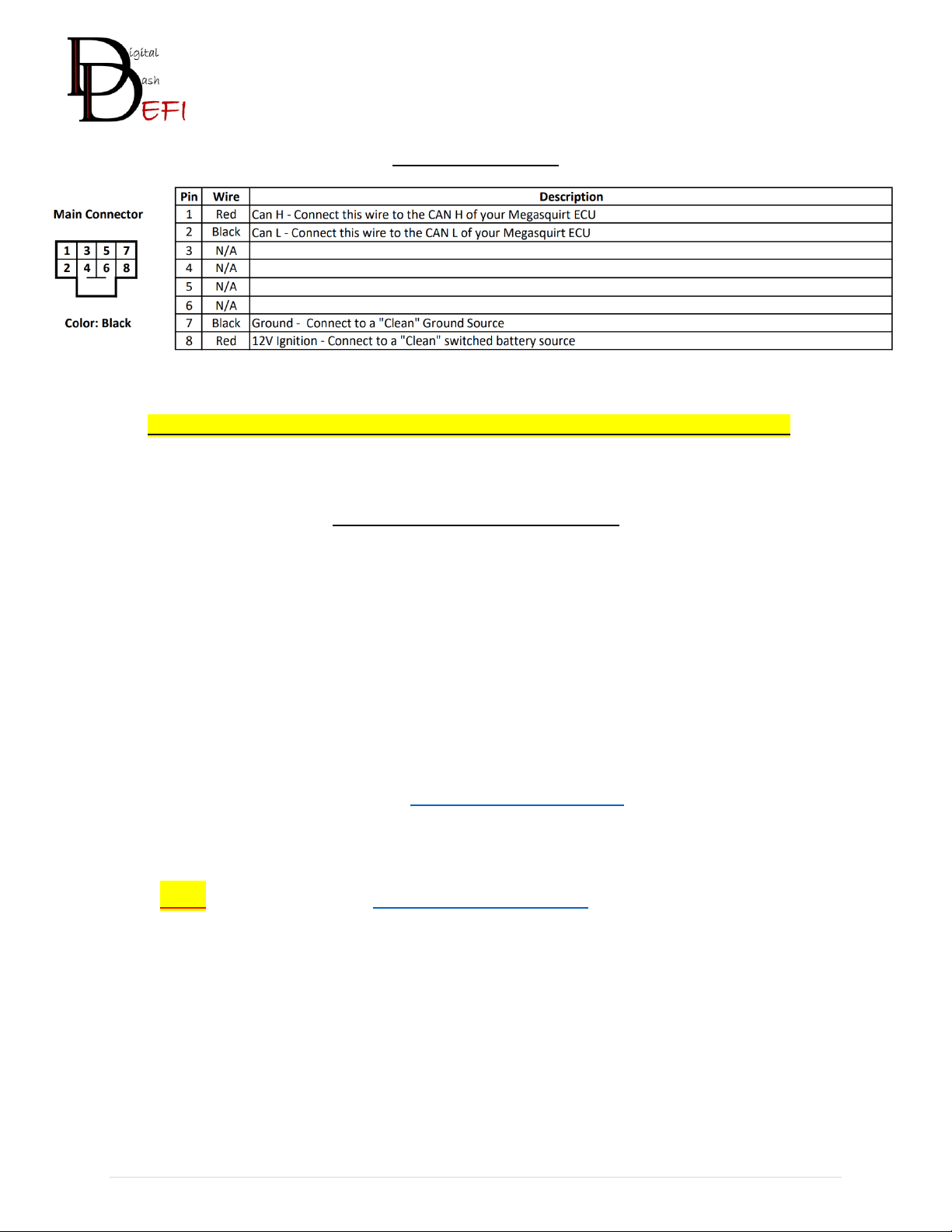
Main Connector
Connection from Module to ECU: Wire the Can H/L Wires to the ECU Can H/L Wires
Dash Setup & Configuration
After the assembly process of your Expansion Module, you were
requested to provide your Current Project.
If you did this, you were emailed an updated copy of your Project.
You will need to delete your old Project and replace it with the one
that we provided to you. If you need assistance in this step please do
contact [email protected]
If you did NOT, please contact support@dd-efi.com to complete this step of the
setup and configuration process.
3 | P a g e
I/O Connectors
The DD-EFI Pro Dash has (2) I/O Connectors for Sensors and Digital Inputs. Below are diagrams outlining what each Pins
location, function, and wire color in the 12 Pin and 10 Pin black connectors. Provided: Sensor and Digital Wiring
Harnesses, 2:6 Lever Lock Connector, (4) T-Tap Connectors (Used for: Fuel Level, L/R Turn Signals, High Beam)
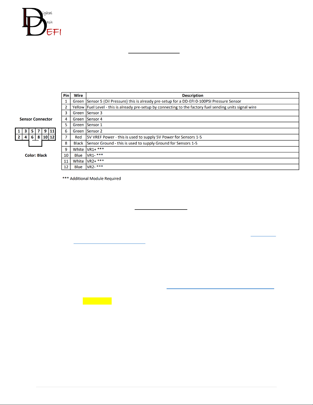
Sensor Connector
•(5) ADC (Sensor) Inputs:
oSensor 5, this is pre-configured in default DD-EFI Dashboards for Oil Pressure
oThis requires a Digital Pressure Sensor, so if you need one, we offer one at https://dd-
efi.com/collections/accessories
•Breakout Board –this is included with any order that purchases sensors directly from us to
simplify the wiring process
•Sensor Wiring:
oAll wiring diagrams are on our website (https://dd-efi.com/pages/technical-resources)
•Fuel Level (Yellow Wire) –this is a pre-configured internal circuit to make the wiring of your
factory vehicle fuel sending unit a single wire connection. Attach the Yellow Wire (Pin 12) to your
vehicles fuel sending unit signal wire. There is a provided T-Tap Wire Connector for easy
connection to your factory wiring.

4 | P a g e
Digital Connector
•(2) PWM Outputs:
oConfigurable for either ON/OFF
oPWM Setup: Extended Control -> PWM Output 1 or 2
oOutputs are low side (Pull to Ground)
oEach capable of up to 6A
•(7) Digital Inputs:
oConfigurable for 12V or GND trigger with internal jumper
oDefault internal jumper set to 12V
oRemoval of the back cover to access jumpers
•Digital Inputs 1, 2 & 3 - pre-configured in DD-EFI Dashboards for
oProvided T-Tap Wire Connector(s) for easy connection
oLeft Turn Signal - Digital Input 1
oRight Turn Signal - Digital Input 2
oHigh Beam –Digital Input 3
•Push Button Start
oSetup: Extended Control -> Push Button Start
oInput Port
▪Select one of the available Digital Inputs
▪This typically comes from the output of the push start button;
the inputs are preconfigured for 12v input.
oOutput Port
▪Select one of the available PWM Outputs
▪These outputs provide a ground signal and are typically wired to
a relay that will provide the 12v to the starter solenoid.
•Examples of other Digital Inputs uses:
oFactory Indicators –High Beam, Low Level Indicators, etc.
oAC Idle Up
oLaunch Control

5 | P a g e
Disclaimer
Digital Dash EFI LLC makes no affiliations, representations, endorsements, sponsorships, or associations
with the Raspberry Pi Foundation or EFI Analytics.
Digital Dash EFI LLC makes no representations or warranties of any type with respect to the contents in
this manual. Digital Dash EFI LLC disclaims any implied warranties or fitness for any particular purpose.
Digital Dash EFI LLC is not liable for any errors contained within or for incidental or consequential damages
in connection with the supply, performance or use of the hardware and software or this manual.
Digital Dash EFI LLC reserves the right to revise this installation and user manual at any time, without
obligation to notify any person of revisions. As defined by the Magnuson-Moss warranty Act, do not install
any products or services unless you have the technical ability to properly set-up the entire vehicle to
compensate for the installation of those products or services. The necessary work and expertise needed
to install different products varies. Instructions, where provided, are given to assist in the installation only;
they are not a substitute for mechanical experience in setting up vehicles. Digital Dash EFI LLC is not
responsible for any personal or property damages caused by the installation of this product.
Warranty
Digital Dash EFI LLC makes every effort to ensure our products and services are of the highest quality and
standards. This warranty applies to the ORIGINAL PURCHASER of this product and covers only those
products exposed to normal use or service. Digital Dash EFI LLC warrants all merchandise manufactured
by Digital Dash EFI LLC against defects in workmanship or material for a period of six (6) months after the
date of purchase. This warranty does not apply to any product that has been damaged through alteration,
improper installation, mishandling, misuse, neglect, or accident. Any part or product found to be
defective after examination by Digital Dash EFI LLC will be repaired or replaced. Digital Dash EFI LLC
assumes no responsibility for loss of time, diagnosis, removal and/or installation labor, loss of vehicle use,
inconvenience or any other consequential expenses.
This Warranty is in lieu of all other expressed warranties or liabilities. Any implied warranties, including
any implied warranty of merchantability, shall be limited to the duration of this written warranty.
If you have any questions regarding warranty, please contact support at Digital Dash EFI LLC at
WARNING: California’s Proposition 65 requires that a clear and visible warning be provided to consumers in California that have
the potential to expose them to various substances which may cause cancer, birth defects or other reproductive harm. Many of
the products of Digital Dash EFI LLC utilizes manufactured products from Aluminum, Plastics, and other standard materials. These
products can expose you to chemicals including lead, which is known to the State of California to cause cancer and birth defects
or other reproductive harm. For more information go to www.P65Warnings.ca.gov
Table of contents
Other DD-EFI Automobile Accessories manuals

Popular Automobile Accessories manuals by other brands


Big Mikes Performance Parts
Big Mikes Performance Parts STO N SHO SNS 28a Installation procedures

Menabo
Menabo SHADOW CADDY Fitting instructions

travall
travall TDG 1602D Fitting instructions

Connects2
Connects2 CT23MB25/L instruction manual

CITROEN
CITROEN C3 Accessories guide

TOP VEHICLE TECH
TOP VEHICLE TECH GRKST04 installation manual


