ddtop UFZ-4A User manual

1/ 9
WWW.DDTOP.COM
UFZ
BUOY LEVEL GAUGE
UFZ 型浮标液位计
使用说明书
Operation Manual
UFZ-DT-JS-1011-2018(
A)

2/ 9
WWW.DDTOP.COM
Preface
Thank you for choosing the products of Dandong Top Electronics Instrument (Group) Co., Ltd.
This operation manual provides you with important information on installation, connection and
commissioning as well as on maintenance, troubleshooting and storage. Please read it carefully
before installation and commissioning and keep it as part of the product near the meter for easy
reading.
This manual can be downloaded by entering the version number at www.ddtop.com .
If the instructions are not followed, the protection provided by the meter may be destroyed.
Trademark, Copyright and Restriction Instructions
Dandong Top Electronics Instrument (Group) Co.,Ltd.®, Dandong Top Pump Co., Ltd.®, DDTOP®
are registered trademarks of the company.
The performance specifications of the meter are effective as of the date of publication and are
subject to change without notice. Dandong Top Electronics Instrument (Group)Co.,Ltd. reserves the
right to modify the products described in this manual at any time without prior notice.
Quality Assurance
Dandong Top Electronics Instrument (Group) Co.,Ltd. guarantees that all glass plate level gauge
have no defects in materials and manufacturing processes within one year from the date of delivery.
During the warranty period, if the product returns with quality problems and the claim is
determined by the manufacturer to be within the scope of warranty, Dandong Top Electronics
Instrument (Group) Co.,Ltd. is responsible for repair or replacement of the buyer (or owner) free of
charge.
Dandong Top Electronics Instrument (Group) Co.,Ltd. is not responsible for the costs caused by
improper use of equipment, labor claims, direct or subsequent damage and installation and use of
equipment. In addition to the special written warranty certificate for certain products of Dandong
Top Electronics Instrument (Group) Co.,Ltd., Dandong Top Electronics Instrument (Group) Co.,Ltd.
does not provide any express or implied warranty.
Quality
Dandong Top Electronics Instrument (Group) Co.,Ltd. has passed the ISO9001 quality system
certification. The whole process of product production is strictly in accordance with the scope of the
quality system, providing the strongest guarantee for product and service quality.

3/ 9
WWW.DDTOP.COM
Contents
1. Safety Tips ...................................................................................................................................................................... 4
1.1 Explosion May Result In Death or Serious Injury. ...................................................................................... 4
1.2 Process Leaks Can Cause Serious Injury or Death..................................................................................... 4
1.3 Failure to Follow Safe Installation Guidelines May Result In Death or Serious Injury.................... 4
2. Product Manual............................................................................................................................................................ 4
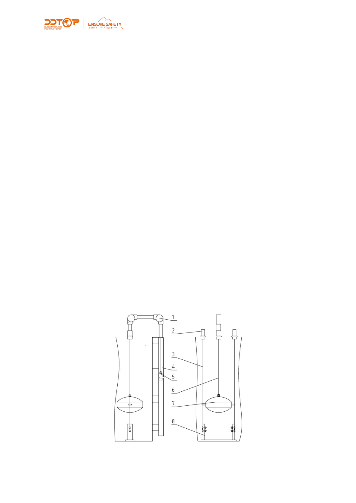
2.1Main Structure of Product-Figure 1..................................................................................................................... 4
2.2 Operating Principle.............................................................................................................................................. 5
2.3 Packing..................................................................................................................................................................... 5
2.4 2.4 Transporting.................................................................................................................................................... 5
2.5 Warehousing.......................................................................................................................................................... 5
3. Technical Characteristics............................................................................................................................................ 5
3.1 Main Performance................................................................................................................................................ 5
3.2 Main Performance................................................................................................................................................ 5
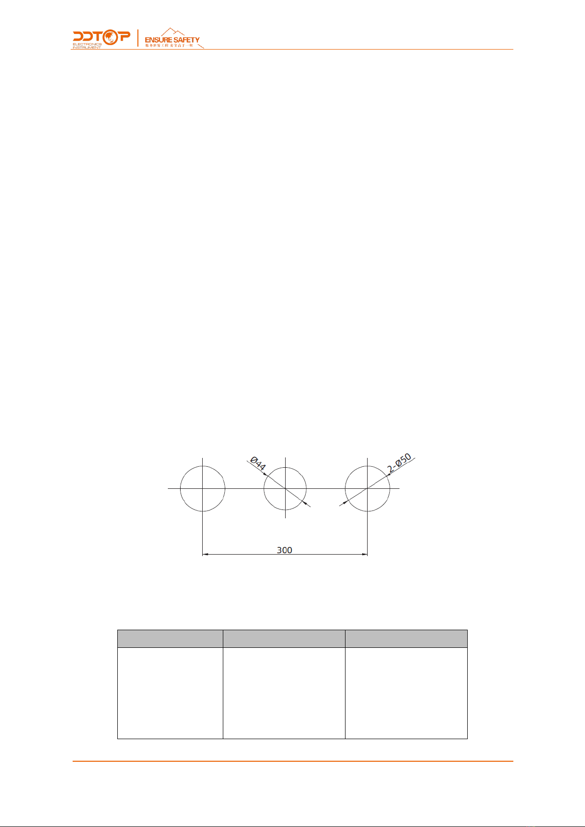
4 Dimensional Schematic -Figure 2 ........................................................................................................................... 6
5 Unpacking and Inspection ......................................................................................................................................... 6
5.1 Unpacking Inspection Notice ........................................................................................................................... 6
5.2 Check Content....................................................................................................................................................... 6
6 Installation ....................................................................................................................................................................... 7
6.1 Installation Tool..................................................................................................................................................... 7
6.2 Installation Technical Requirements............................................................................................................... 7
6.3 Installation Process-Figure 6 ............................................................................................................................ 8
7. Fault Analysis and Elimination ................................................................................................................................. 8
8 Disassembly .................................................................................................................................................................... 9
8.1 Warning ................................................................................................................................................................... 9
8.2 Waste Removal...................................................................................................................................................... 9
9 Product Certification.................................................................................................................................................... 9

4/ 9
WWW.DDTOP.COM
1. Safety Tips
It is expressly prohibited to modify or change products for safety reasons,repair or replacement
only allows the use of accessories specified by the manufacturer.
1.1 Explosion May Result In Death or Serious Injury.
When installing equipment in an explosive atmosphere, be sure to follow applicable local, national,
international standards, codes, and procedures. Be sure to install the equipment in Intrinsically safe
or non-flammable site operating procedures.
1.2 Process Leaks Can Cause Serious Injury or Death.
Care should be taken to lift the transmitter. If the process seal is damaged, the medium may leak at
the joint.
1.3 Failure to Follow Safe Installation Guidelines May Result In Death or Serious Injury.
The operations described in this manual are performed by professionally trained and qualified
professionals or end-user specialized professionals to complete.
2. Product Manual
2.1Main Structure of Product-Figure 1
Figure 1 Main Product Structure

5/ 9
WWW.DDTOP.COM
1. Transmission Mechanism
2. Tensioning Mechanism
3. Guide Wire Rope
4. Ruler
5. Heavy Hammer
6. Transmission Wire Rope
7. Buoy
8. Guiding Mechanism
2.2 Operating Principle
The UFZ-4A buoy level gauge is designed according to the principle of force balance. The working
principle is shown in Figure 1. Let the weight of the float be W, the buoyancy of the float be F, the
weight of the pointer weight be G, and the friction of the whole system be f. When the float is
immersed in a position in the liquid, these forces are in equilibrium. W-F-G±f=0. When the level
changes, it causes the change of the position of the float. The pointer hammer is moved by the wire
rope, and the corresponding position of the level is displayed on the scale to achieve the purpose of
level measurement.
2.3 Packing
Please send the packaging waste to a special recycling agency.
2.4 Transporting
When hoisting and transporting, please select qualified hoisting equipment and lifting straps, and
pay attention to safety.
2.5 Warehousing
Storage Temperature -20℃~40℃; Storage Humidity≤40%.
3. Technical Characteristics
3.1 Main Performance
3.1.1 Product implementation standards:Q/AMM005-2010
3.2 Main Performance
3.2.1 Medium density:≥0.6g/cm3
3.2.2 On-site indication accuracy: ±20mm

6/ 9
WWW.DDTOP.COM
4 Dimensional Schematic -Figure 2
If the order is required to be a special size, the actual size will prevail.
Figure 2 Dimensional Schematic
5 Unpacking and Inspection
5.1 Unpacking Inspection Notice
5.1.1 Check whether the product nameplate (Figure 3) is consistent with the supply list information.
Figure3 Sample Nameplate
5.1.2 Check the quantity of each part against the packing list and the material is correct.
5.2 Check Content
5.2.1 Check the appearance of the instrument for defects, damage and other abnormal conditions.

7/ 9
WWW.DDTOP.COM
6 Installation
6.1 Installation Tool
6.1.1 Wrench, flange gasket and flange bolts for process connections.
6.1.2 Level
6.2 Installation Technical Requirements
6.2.1 According to the position of the scale, the fixing bracket of the welding scale should be placed
on a vertical line with a deviation of ≤ 2° (Figure 4).
Figure 4 Installation
6.2.2 The bottom guiding mechanism and the buoy are taken into the tank from the inlet hole. By
observing the perpendicularity of the guide wire at the top, it is determined that ≤ 2°, and the
bottom guiding mechanism is welded and fixed to the bottom of the tank. (Figure 5)
Figure 5 Installation

8/ 9
WWW.DDTOP.COM
6.3 Installation Process-Figure 6
6.3.1According to the site requirements of the tank, the observation direction of the scale, the
opening position of the tank top, and the welding position of the bottom mechanism are
determined.
6.3.2The mounting bracket of the scale is welded according to the position of the scale.
6.3.3Connect the overall display scale to the scale mounting bracket.
6.3.4 Take out the top transmission mechanism, and the tensioning mechanism determines the
opening position of the tank top. After the error is correct, follow the installation diagram to open
the tank (Figure 6).
6.3.5 Install the drive wire rope and the guide wire rope and pass it into the storage tank.
6.3.6 The bottom guiding mechanism and the buoy are taken into the tank from the inlet hole. By
observing the perpendicularity of the guide wire at the top, it is determined that ≤ 2°, and the
bottom guiding mechanism is welded and fixed to the bottom of the tank.
6.3.7The guide wire is passed through the side hole of the float and fixed on the bottom guiding
mechanism to ensure the tension and verticality of the wire rope.
6.3.8 One end of the transmission wire rope is connected with the float, the other end is connected
to the weight by two pulleys, and the float is gently lifted in the tank, and the pointer on the heavy
hammer outside the tank is simultaneously moved and slid freely.
Figure 6 Installation procedure
7. Fault Analysis and Elimination
Fault Phenomenon
Cause of Issue
Troubleshooting Method
The buoy moves up and
down inflexibly.
1. Wire rope installation
verticality is too large.
2. The pulley is damaged.
1. Adjust the verticality of the
wire rope installation.
2. Replace the pulley.

9/ 9
WWW.DDTOP.COM
8 Disassembly
8.1 Warning
Attention should be paid to hazardous process conditions, such as pressure inside the vessel, high
temperatures, corrosive or toxic media, etc.
8.2 Waste Removal
Waste disposal should be carried out in accordance with the current guidelines in each region.
9 Product Certification
C
Table of contents
Other ddtop Marine Safety Device manuals