De Agostini Robi User manual

01
Build your own
Stages 1-2:
Begin assembling
Robi’s head, starting
with his eyes
Pack
™

All rihts reserved © 2015
Published in the UK by De Aostini UK Ltd,
Battersea Studios 2, 82 Silverthorne Road,
London SW8 3HE
Published in the USA by
De Aostini Publishin USA Inc.,
915 Broadway, Suite 609, New York, NY 10010
Packaed by Continuo Creative,
39-41 North Road, London N7 9DP
Printed in EU
The names and likenesses of all Robi characters,
artwork and distinctive lettering are protected
under the copyright and trademark laws of the
United States and all foreign countries.
CONTENTS
Build your own
Assembly Guide p3
Your step-by-step guide to building Robi
Stage 1: Preparing Robi’s eyes p3
Stage 2: Start putting together Robi’s head p6
™
www.model-space.com
NOT SUITABLE FOR CHILDREN UNDER THE AGE OF 14.
THIS PRODUCT IS NOT A TOY AND IS NOT DESIGNED FOR USE
IN PLAY. ITEMS MAY VARY FROM THOSE SHOWN. THERE MAY BE
COLOUR VARIATIONS OWING TO THE MATERIALS USED.

STAGE 1:
PREPARING
ROBI’S EYES
The first thin you will do is to start puttin toether Robi’s
eyes. This simply involves wrappin the black centres with
reflective tape, and then fittin the translucent white borders.
PARTS TO BE
ASSEMBLED
1Right ear
2 Right ear trim panel
3 Top of head
4 Eyes (x 2)
5 White borders (x 2)
6 Reflective tapes (x 2)
YOUR PARTS
Robi expresses his dierent states of
emotion and activity by chanin the
colour of his eyes. As the central part
of each eye is a deep black (this is to
conceal a sensor that you will fit later
on), it is the translucent white border
that lihts up when illuminated from
inside by coloured LEDs (also fitted at
a later stae). To diuse the liht
evenly, you need to cover the black
parts of Robi’s eyes with reflective tape
before fittin the borders. This isn’t
dicult, but it needs to be done neatly
to avoid wrinklin the self-adhesive
silver tape, so o slowly and carefully.
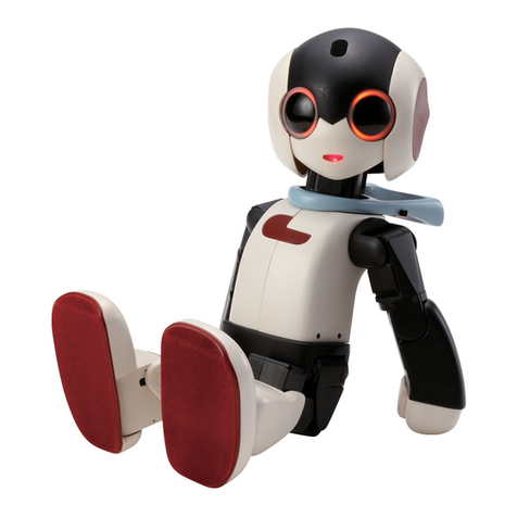
In addition to your first parts, you
have also received a ‘mini Robi’
fiurine. This is a scale model of the
full-size Robi you will be buildin over
the comin staes, ivin you an idea
of his overall proportions and where
the parts fit.
ASSEMBLY GUIDE
1
2
3 4 5
6
03

1 32
45
!
6 7
ADDING REFLECTIVE TAPE
Peel the protective plastic film off
one of the black eyes.
Pull one end of the backin paper o
a strip of reflective tape to expose
about 3cm of the adhesive.
Work slowly and carefully around the
eye until you reach your startin point.
Overlap the end by about 1mm and
smooth it firmly onto the surface.
Repeat Steps 1 to 5 for the second eye.
Very carefully, bein to wrap the
reflective tape around the eye, so
one ede fits just under the rim.
Keepin the tape taut to prevent any creases
formin, radually pull away the remainin
backin paper and smooth the adhesive side
down with your thumb.
Smooth the tape with
your thumb from front
to back to remove any
wrinkles or creases.
After tapin both eyes, they should look like this.
04

ADDING THE WHITE BORDERS
Assembled
eyes
Repeat Step 9 for
the second eye to
complete this stage.
98
BE CAREFUL!
FRONT BACK
Do not force the border on at an
anle. This is harder to do, and may
crease or tear the reflective tape.
Compare the white borders, as shown above, so you
can see which way round they fit. The front is raised
and the back has a recessed rim.
Slide a white border over one of the black eyes, with the raised
front of the border on the same side as the rounded front of
the eye. Be sure to keep the parts straiht.
Store the unused parts away safely in plastic bas until next time.
This will protect the polished surfaces and prevent them from
becomin scratched.
Later on in the assembly, you will be fittin Robi’s eyes with
LEDs, which will illuminate the white borders you have just
fitted. The LEDs come in a rane of colours includin orane,
reen, pink, purple and blue. The colour varies dependin on
Robi’s mood and the activity he is currently performin: for
example, when dancin, his eyes will continuously chane
colour (as well as flash on and o) to the music. Robi’s mouth
is also fitted with an LED that lihts up when he is talkin,
further addin to his expressive qualities.
A FACE THAT LIGHTS UP!
05
KEEP THE PARTS TIDY

STAGE 2: START
PUTTING TOGETHER
ROBI’S HEAD
Usin the screws provided, assemble the framework for
Robi’s head before fittin his eyes and face, after which
Robi’s characteristic features will start to take shape.
It is not dicult to put the head
toether, but note that the two side
frames look similar, so make sure you
don’t et them confused. Use the
specially desined screwdriver
provided with this stae, holdin it as
shown in the ‘Close-Up’ box below. To
complete the assembly you will need
the two eyes that you put toether in
Stae 1, so have these to hand, and
make sure you tape them neatly at
Steps 12-14.
ASSEMBLY GUIDE
123
4
45
6
1 Left head frame
2 Neck mounting
3 Right head frame
4 Eye sockets (x 2)
5 Face
6 Black tape (100mm strips x 2)
7 M2 x 4.5mm countersunk screws
(x 14 – includes 2 spares)
YOUR PARTS
8 Crosshead screwdriver
TOOLS
8
7
The only special tool you need to assemble Robi is the screwdriver that you
received with this stage. The tip is specially designed to fit the small screws that
hold Robi together, and the end of the handle has a revolving pad which is designed
to help you apply even pressure with your palm. This will keep the screw in place
while you turn the handle with your thumb, index and middle fingers. Never grip the
handle itself like a conventional screwdriver. Turning the screws as shown makes it
much easier to put them in straight and reduces the chance of overtightening,
which can damage both the screw and the parts being joined together.
YOUR SPECIAL SCREWDRIVER
PARTS TO BE
ASSEMBLED
06

ASSEMBLING THE FRAMES
12
Before you bein, sort out the left and riht head frames. Lay both of
them out on your work surface, facin each other as shown. Compare
them with the photo to ensure that you can tell the left and riht
frames apart. The two are almost symmetrical, but the back of the
left frame is shorter than the equivalent area on the riht.
Take the neck mountin in your riht hand and
oer up the left head frame as shown. Double-
check that you have selected the correct side.
53 4
Place the parts toether so that
the two holes circled in red line up.
Fit one of the M2 x 4.5mm countersunk
screws into each of the holes and
tihten them with the screwdriver. Be
careful not to overtihten the screws.
Now alin the riht head frame
with the neck mountin as
indicated in red, so that the holes
match as they did in Step 3.
!
86 7
Holdin the parts toether, fit two
M2 x 4.5mm countersunk screws
into the circled holes.
Tihten both screws with the
screwdriver.
That completes the assembly of
the head frames. This view from
above shows which way round it
will fit in the head.
Left head frame Right head frame
Short
Long
Left
Front
Back
Right
07

ASSEMBLING ROBI’S EYES
10 Take either of the silver eye
sockets and look for a small notch
in the silver rim, above the two
screw holes.
12 Holdin the eye in place, take
one strip of black tape and start
wrappin it around the ede of
the white border, peelin away
the backin paper as you o.
Make sure that the tape does not
overlap the front of the eye.
1413 There is more than enouh tape to
o round once, so continue wrappin
when you reach the startin point
– it is not necessary to cut the tape.
Repeat Steps 9-13 for the second
eye and eye socket. You will see
that there is no dierence between
the left and riht eyes.
11 Insert the eye into the socket, so that the projection circled in Step 9 fits
into the notch in the rim and the parts fit toether snuly.
Right head frame
9
TIP!
If you have diculty
findin the projection
indicated in the photo on
the left, turn the eye
over. You will see that the
white border is slihtly
wider on one side, and
narrower on the other.
The projection is situated
directly below the widest
point of the white border.
Lay either of the eyes assembled in Stae 1 face down on your
worktop. Find the sinle small projection on the outer ede of
the white border.
Location of
the projection
08

17 18
FITTING ROBI’S EYES
Holdin the parts toether, insert and tihten two of the M2 x
4.5mm countersunk screws.
19 20
Repeat Steps 15-18 to attach the left eye. You may find this
easier if you turn the head frame assembly upside down as
shown.
Your assembly should look like this. Check
that the wider part of the whites of Robi’s
eyes are towards the outside of his head.
Insert the eye behind the head frame, and
alin the holes so that they are ready to be
screwed toether.
15 16
Pick up either of the completed eye
assemblies. The first one you fit will
become Robi’s riht eye.
Hold the head framework from Step 8 as shown, turnin the eye
around until the circled holes in the eye frame line up with those on
the riht of the head frame.
09

FITTING ROBI’S FACE
21 22
Line up the face with the head assembly, as shown.
The two curves on the upper ede fit aainst the edes
of the eyes.
Fit the face between the left and riht head frames so
that the screw holes on the left and riht sides of the
face line up with the correspondin holes circled in red.
24 Turn the assembly
over and repeat
Step 23 on the
left of the face. That completes this stage of the
assembly, with the features of Robi’s
face beginning to take shape. Store it
carefully until next time.
23 Insert two of the
M2 x 4.5mm
countersunk screws
into the holes on
the riht side of the
head, indicated in
Step 22. Tihten
with the
screwdriver.
Assembled
head frame
10

In your next pack – 02
BUILD YOUR OWN
PARTS PROVIDED
Components for Robi’s neck stand, which will
be used to test the movement of Robi’s head.
Stage 3
Begin assembling
the neck stand
PARTS PROVIDED
More parts for Robi’s head and neck stand, plus the
rst of the servo motors that enable him to move.
Stage 4
Continue building Robi’s head, and
assemble your first servo motor
Stage 5
Complete the neck stand, and fit the
servo that will move Robi’s head
PARTS PROVIDED
The nal components that make up the outer
casing of Robi’s neck stand.
Stage 6
See the first of Robi’s moving parts in
action, as you test his head servo
PARTS PROVIDED
The battery pack that will power Robi’s servos,
and another servo cable.
Your next FOUR complete
Stages, as Robi starts to
come to life!
Other De Agostini Robotics manuals
