De Agostini Model Space Robi Pack 05 User manual

Build your own
Stages 15-18:
Begin building
Robi’s left arm
05
Pack

All rights reserved © 2015
Published in the UK by De Agostini UK Ltd,
Battersea Studios 2, 82 Silverthorne Road,
London SW8 3HE
Published in the USA by
De Agostini Publishing USA Inc.,
915 Broadway, Suite 609, New York, NY 10010
Packaged by Continuo Creative,
39-41 North Road, London N7 9DP
Printed in EU
The names and likenesses of all Robi characters,
artwork and distinctive lettering are protected
under the copyright and trademark laws of the
United States and all foreign countries.
Assembly Guide p78
Stage 15: Assembling Robi’s left forearm p78
Stage 16: Set the ID of Robi’s left forearm servo p81
Stage 17: Completing Robi’s left forearm p86
Stage 18: Building up Robi’s left upper arm p90
CONTENTS
™
www.model-space.com
NOT SUITABLE FOR CHILDREN UNDER THE AGE OF 14.
THIS PRODUCT IS NOT A TOY AND IS NOT DESIGNED FOR USE
IN PLAY. ITEMS MAY VARY FROM THOSE SHOWN. THERE MAY BE
COLOUR VARIATIONS OWING TO THE MATERIALS USED.
Build your own

STAGE 15: ASSEMBLING
ROBI’S LEFT FOREARM
In this stae you will start assemblin Robi’s left arm, beinnin
by fittin the thumb to the forearm frame. You will then prepare
another servo cable by fittin it with protective pads.
Robi’s left arm is symmetrical to his
riht, so the assembly process is
nearly identical. Aain, the servos that
operate his arm’s movement will be
fitted onto a framework, the forearm
section of which is supplied with this
stae. After startin the physical
assembly, you will o on to prepare the
servo cable that will carry power to
Robi’s forearm servo on completion.
As always, care must be taken when
handlin delicate electronic parts.
ASSEMBLY GUIDE
1
2
3
45
6
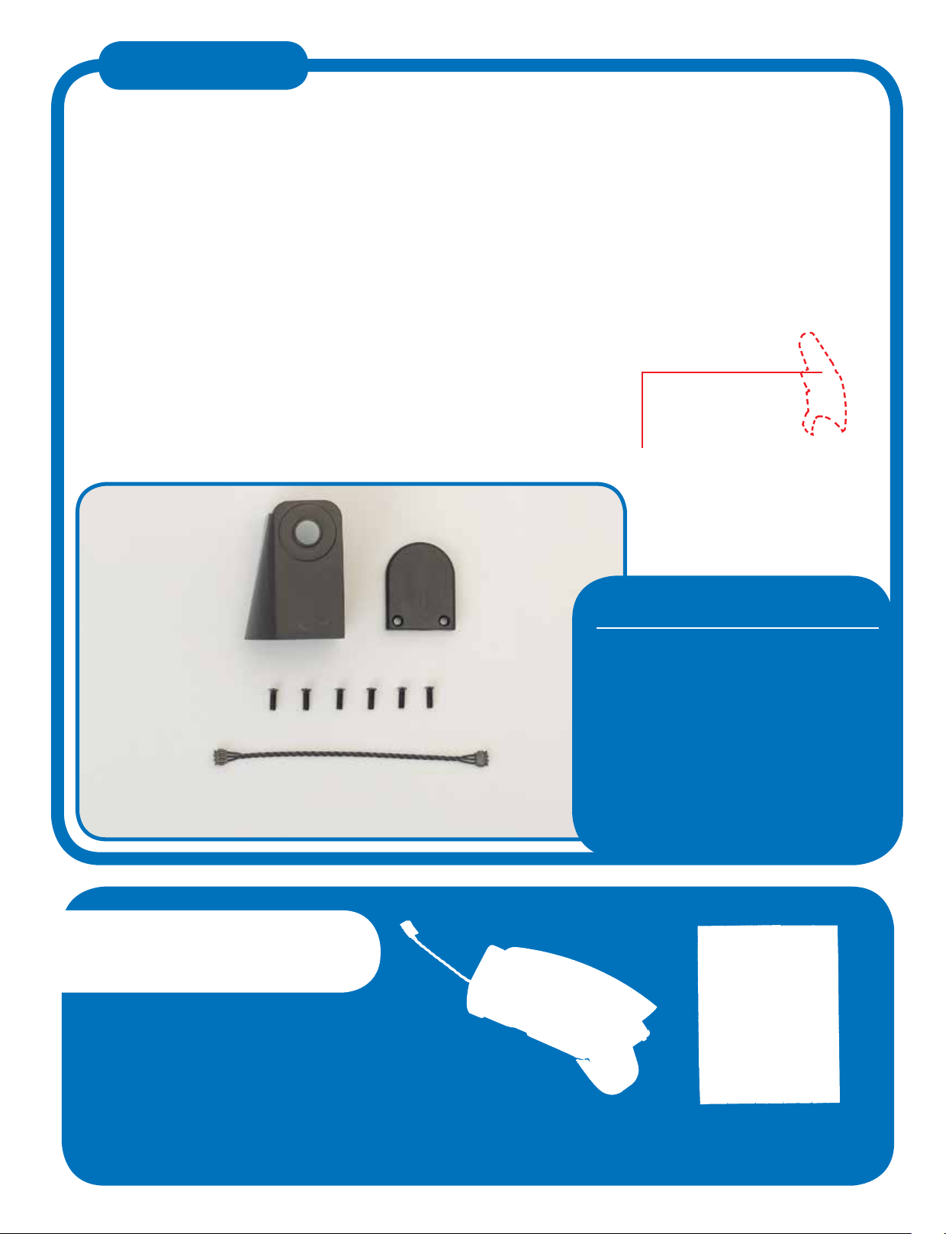
1 Left forearm frame
2 Left thumb
3 Left finger mount
4 M2 x 5mm pan-head screws (x 2)
5 M2 x 10mm pan-head screws (x 3)
6 Servo cable (70mm long)
You will be usin the protective pads
supplied with Stae 3, so be sure to
have these to hand before beinnin.
SAVED PARTS
YOUR PARTS
PARTS TO BE
ASSEMBLED
Protective pads (Stage 3)
78

THE FINGER MOUNT
THE THUMB
3
1
5
Turn the forearm frame over to check that the holes in
the finer mount are in line with the two screw holes in
the forearm frame.
Alin the left forearm frame and finer mount as
shown. The mount can be fitted either way up.
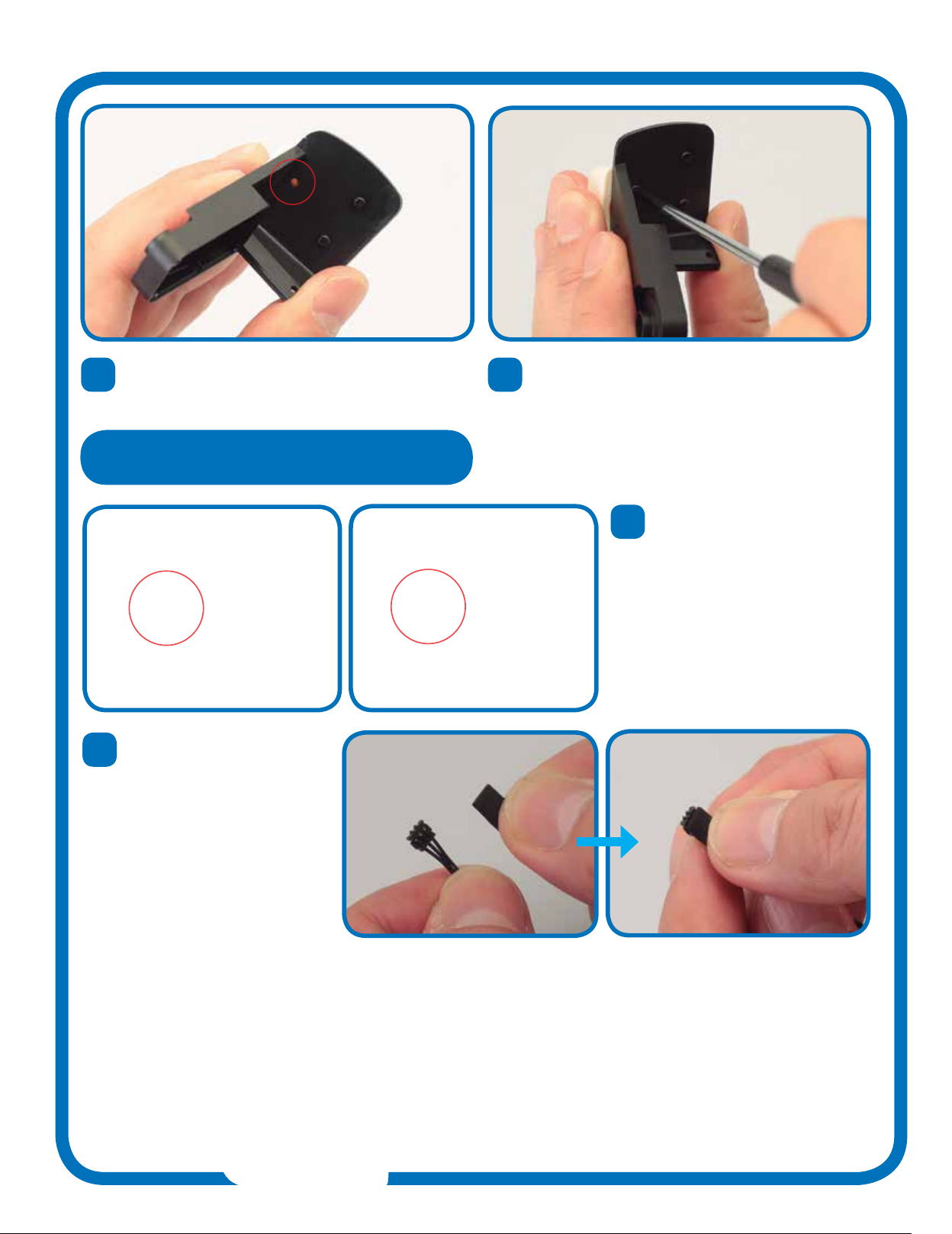
Line up the thumb and the forearm frame, notin the
position of the square tab on the thumb and the
matchin hole in the frame, circled in red.
4Fit two M2 x 10mm pan-head screws throuh the holes
and carefully tihten them to secure the finer mount.
2Press the tonue of the finer mount into the lon slot
in the end of the forearm frame.
6Press the parts toether so that the tab locks into the
hole and the thumb fits flush aainst the frame.
79
9
10
Next, prepare the servo
cable supplied with this stae.
As you have done with previous
cables, identify the side of the
connector with PUSH printed
on it. The protective pad will be
fitted to this side.
Remove a protective pad from
the sheet saved from Stae 3,
and press it into place as shown
onto the servo cable’s connector.
Repeat for the connector at the
other end of the cable.
7Turn the forearm frame over and check that the hole in
the thumb is in line with the remainin screw hole in
the forearm frame.
8Fit an M2 x 5mm pan-head screw in the hole and
carefully tihten it, to secure the mount.
Assembled
left forearm
frame
The rst parts of Robi’s left arm
have been assembled, and another
servo cable is ready for use in the
coming assemblies.
THE SERVO CABLE
80

STAGE 16: SET THE
ID NUMBER OF ROBI’S
LEFT FOREARM SERVO
In this stae, you will set the ID number of the servo that acts
as an elbow joint to move Robi’s left forearm, before fittin the
part onto the left forearm frame, ready for use.
The work in this assembly will be
similar to that of Stae 8, when you
wired and set the ID number of the
correspondin servo for Robi’s riht
arm. Even so, make sure you follow
the assembly steps closely, as it can
be dicult and, for the electronic parts
such as the servo cables, even
damain, to re-open the assembly
should you need to o back and
perform the steps aain.
Similarly, when settin the servo’s ID,
be absolutely sure you choose the
correct number, as Robi may not work
properly if the part is set to the wron
number when operated.
ASSEMBLY GUIDE
1
1 Servo motor
(for left elbow)
You will be usin parts from the
previous staes, so be sure to have
these to hand before beinnin.
SAVED PARTS
YOUR PARTS
PARTS TO BE
ASSEMBLED
Servo cable and left forearm
frame (Stage 15) Neck stand (Stage 8)
81
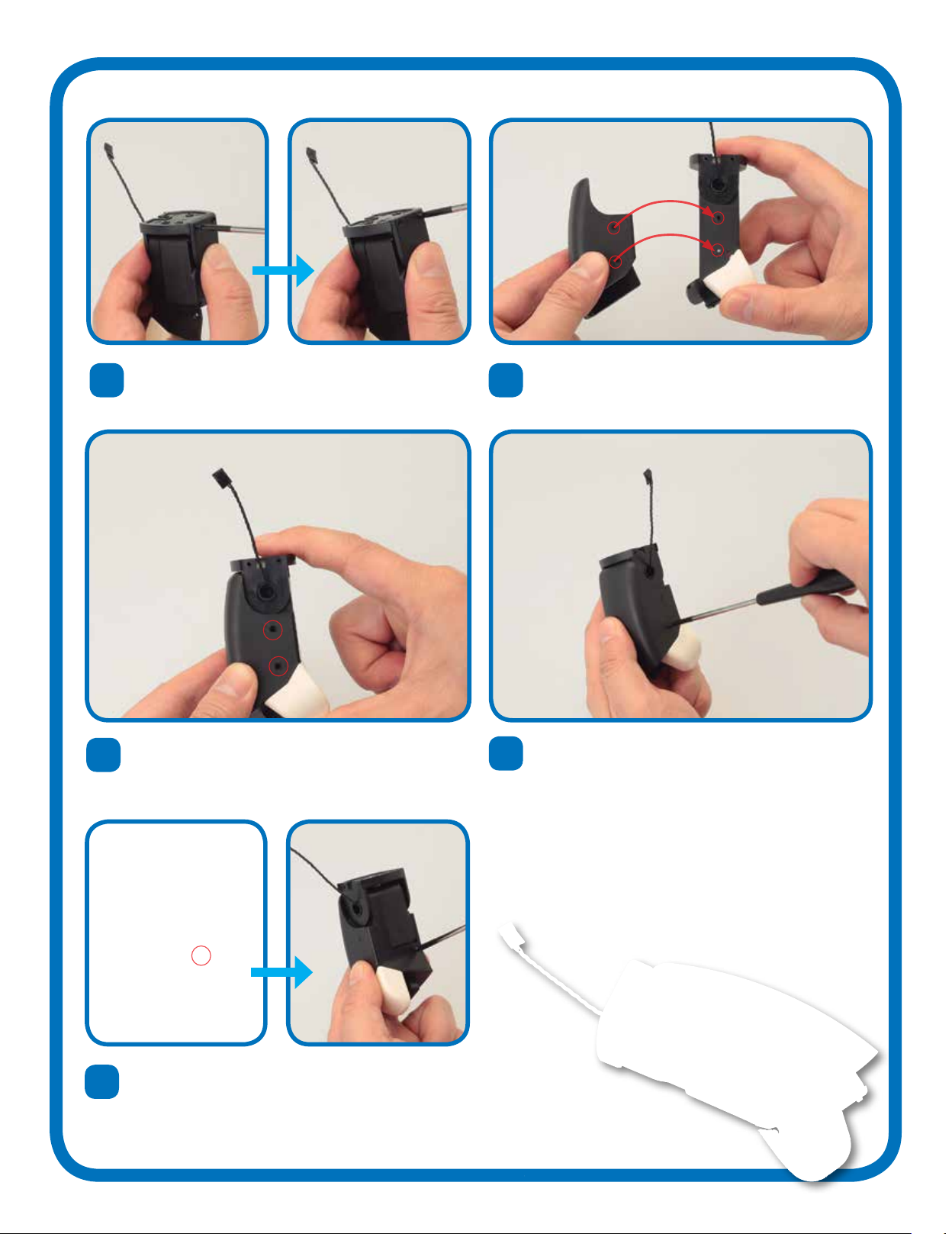
CONNECTING THE SERVO CABLE
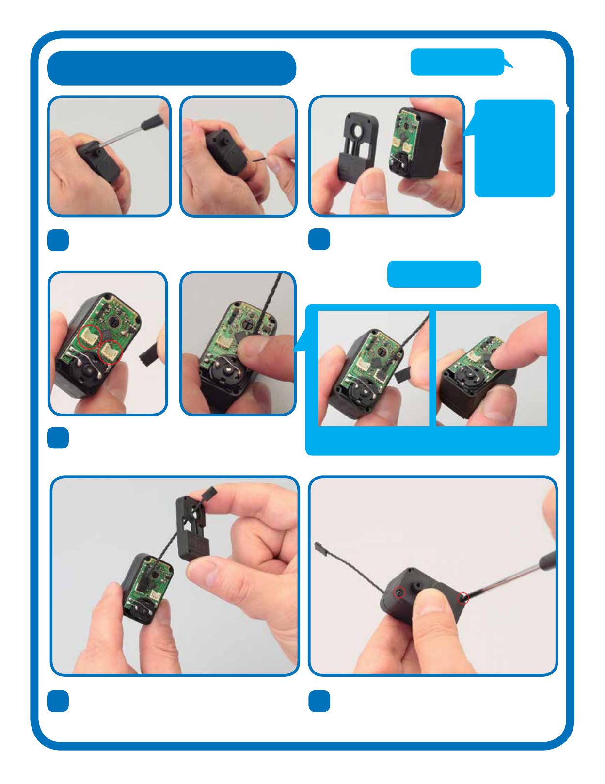
3Take either end of the connector cable saved from the
previous stae and carefully fit it in one of the two
sockets circled in red. It does not matter which one.
Gently push it until it locks in place.
1Use a screwdriver to undo the four screws securin the
cover of the servo, and take each one out.
4Carefully feed the free end of the cable up throuh the
circular hole in the servo cover. Make sure that the cover
is the riht way up.
5Fit the cover onto the servo casin, then turn the servo
over and insert two of the screws you removed in Step 1.
Tihten them lihtly, as you will be removin them aain
in this assembly.
2Carefully lift the cover away from
the other side of the servo.
BE CAREFUL!
Try to avoid
touching the
circuit board
or electronic
components
when you remove
the cover from
the servo.
TIP!
If you chose not to fit the protective pad in Stae 15, you can fit it
now, which will help to secure the connector in place.
82

6Take the neck stand and unplu the black servo cable
from the socket on the left of the test board. Plu the
cable leadin to this stae’s servo in its place.
HELP!
If the LEDs flash rapidly when
you run the test at Step 14, you
have a faulty connection.
Double-check the servo cable’s
connection to the socket on the
test board, TURNING THE
POWER PACK OFF BEFORE
YOU DO. If the liht still flashes,
carefully unscrew the servo
housin and check that the
internal connector plu is in
place. If you pressed the wron
button, reset the board by
holdin down the TEST/SET
switch for several seconds.
9The shaft at the top of the servo casin should rotate 45 derees to the left,
stop, then move back across to 45 derees to the riht. After you have run
the test, turn o the power switch on the battery pack.
TESTING THE SERVO
7Turn the test board to ON. All the LEDs should blink
twice, then turn o to leave only number 1 lit.
8Now press the TEST/SET switch
briefly to run the servo test.
Units
Tens
10 Re-familiarise yourself with the lihts and switches on the test board, which you
have used to set the servos’ ID numbers. Each time you press the UP switch, the ID
number increases by one, and the result is displayed by the two banks of LED
lihts. The top row reads in tens and the bottom in units. For example, to set the ID
to 21, press UP 20 times. This will liht up the 20 LED and the 1 LED. (If you
overshoot, press the DOWN switch to take it down one step at a time.) When the
ID number is correct, you set it by pressin and holdin the TEST/SET switch.
83

15 Once all is well, switch the power pack OFF, then carefully
unplu the servo from the test board. It will retain its settin,
ready to be fitted to Robi’s left arm.
11 To set the ID number of the servo to
21, press the UP button 20 times. The
20 and 1 LEDs should remain lit once
you have done this.
13 It is vital that each of Robi’s servos is prorammed to the correct ID number,
or his operation may malfunction on completion. To bein checkin the ID
number, leave the servo connected, switch the power OFF and then back ON.
Only the 1 LED should liht up.
14 To check the ID number, press
TEST/SET. Now the 20 and 1
LEDs should liht up.
12 Confirm the settin by pressin the
TEST/SET button. The 20 and 1 lihts
should flash, then o out.
SETTING THE ID NUMBER
CHECKING THE ID NUMBER
It is normal for the 1 LED to
light up when you switch on. It
will only change to give you the
ID number of the servo when
you press TEST/SET. If you
made a mistake and set the
wrong ID number, you can reset
it by going through the setting
procedure again.
ID=21
TIP!
84

16 Remove the two screws fitted temporarily in Step 5 and
discard the cover as you will not be usin it aain. Keep
the screws.
17 Now line up the open servo with the left forearm frame.
The servo cable will fit throuh the circular hole at the
top of the frame (circled).
18 19
Carefully feed the servo cable throuh the hole in the
forearm frame.
Press the servo into place at the top of the forearm
frame. Make sure the servo cable is not bent or cauht
in any way as you do this.
20 Usin the four screws you removed in Step 1, secure
the servo to the forearm frame.
The next of Robi’s servos is in place,
ready to be joined to the rest of his
body in future stages.
Assembled
forearm
ATTACHING THE SERVO
85
STAGE 17: COMPLETING
ROBI’S LEFT FOREARM
In this stae, you finalise the parts that make up Robi’s
left forearm, from his elbow joint and forearm cover
down to his hand.
In this session, you continue to
assemble Robi’s left forearm, carryin
on from settin the ID number of the
forearm servo in the last stae. This
time, you will fit the elbow joint and
forearm cover, before closin the
assembly with the servo front panel. At
the end of this session, the left forearm
will be ready to be joined to the upper
arm servo in comin staes.
ASSEMBLY GUIDE
1 2
3
4 5
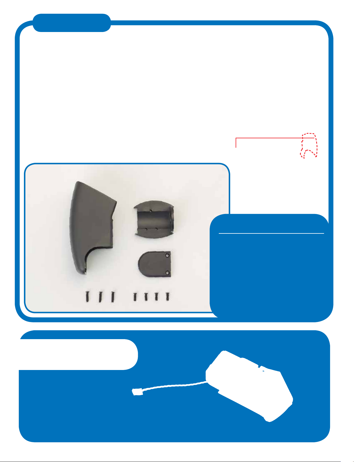
1 Left forearm cover
2 Left elbow joint
3 Servo front panel
4 M2 x 8mm countersunk screws x 3
5 M2 x 6mm countersunk screws x 4
You will be usin parts from the
previous staes, so be sure to have
these to hand before beinnin.
SAVED PARTS
YOUR PARTS
PARTS TO BE
ASSEMBLED
Left forearm assembly
(Stage 16)
86

The round shafts of Robi’s servos are moulded with a small flat
ede on one side – seen end-on, they are shaped like the letter
‘D’ – that fits into a correspondinly shaped recess on the part
that the servo will drive. This ensures that the parts can be set
correctly when in the neutral position.
THE D-CUT
Restorin to the neutral position
If somethin oes wron when you are testin one of
Robi’s servos – for example, if the power is accidentally
disconnected and the servo’s shaft stops turnin and
remains at an anle – you will need to reset the servo to
its neutral position. To do this, identify the flat on the
servo shaft (left photo) and place the part it will operate
over it at the same anle (riht photo). Then, very ently,
rotate the part back to the neutral position, with the servo
shaft’s flat facin downwards.
A ‘D-cut' shaft
Left photo: The servo’s shaft is termed ‘D-cut’ because, viewed
end-on, it isn’t completely circular but has a D-shaped outline.
Riht photo: The hole into which the D-cut servo shaft will fit has
a similarly shaped outline.
Neutral position
The advantae of usin a D-cut shaft and joint set-up is
that it makes it very easy to assemble Robi’s servos and their
accompanyin parts correctly. When a servo and a part are
alined correctly, as in the far left photo, they will fit toether
easily, but if they are not lined up as they should be, they will
strule to fit toether and result in an o-centred neutral
position (near left). If this happens, do not force the part.
Instead, realin it with the servo shaft
until it fits easily.
Warning: applying too much force when
tting a part over the servo’s shaft
can result in damage to both items!
ASSEMBLY GUIDE
87
COMPLETING THE LEFT FOREARM
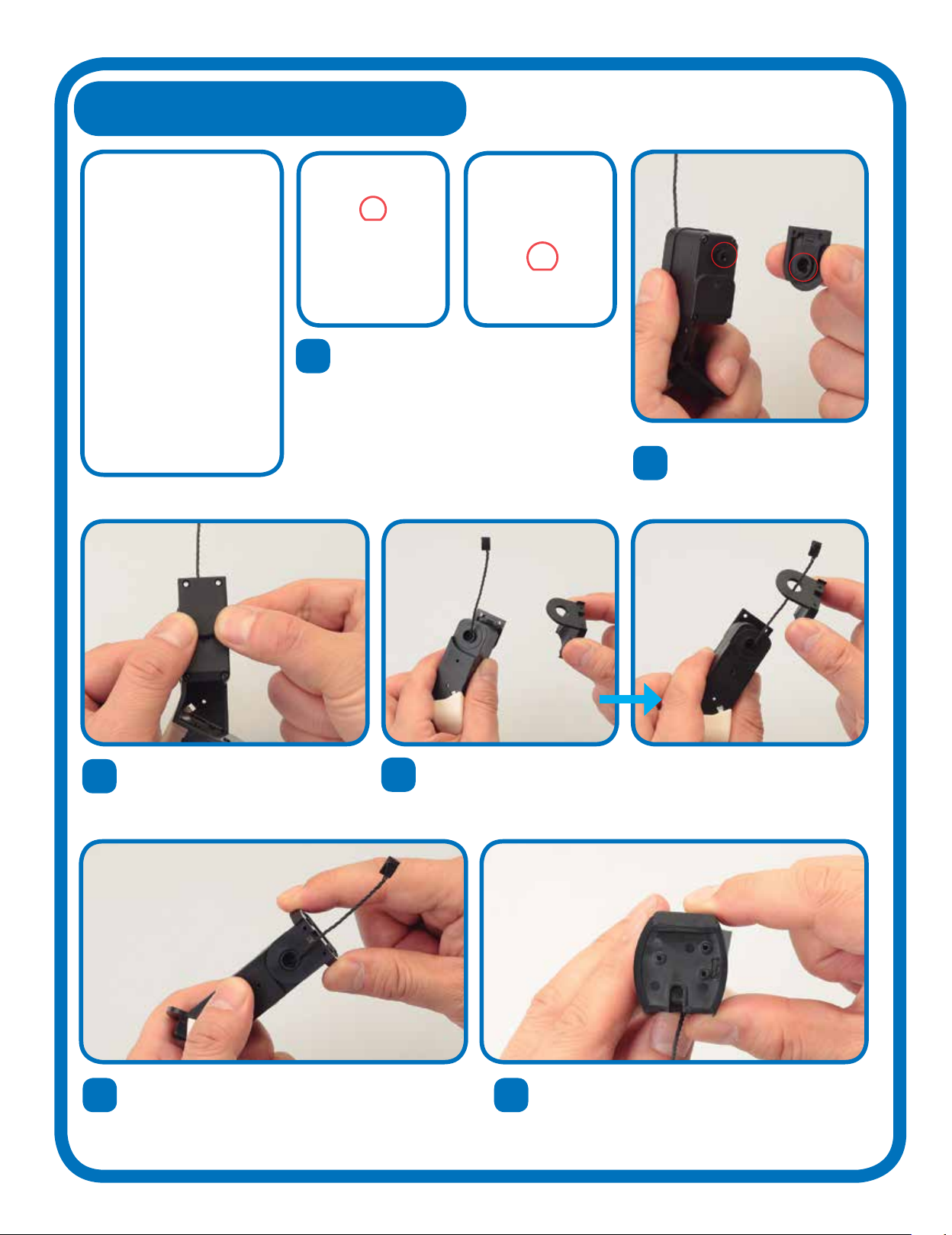
1Take the left forearm assembly and the
servo front panel supplied with this stae,
and line up the D-shaped servo shaft with
the correspondinly shaped socket on the
underside of the servo cover. Be absolutely
sure that the parts are set correctly toether
to avoid damae to either part – for more
information, see the box about D-cuts on
the previous pae.
5Run the left elbow joint alon the whole of the servo
cable, then fit it onto the top of the left elbow frame,
as shown.
6The top ede of the elbow joint is moulded to
accommodate the upper tip of the servo cover fitted
in Step 2, so ently press these toether.
2Join the parts so that they fit
snuly toether. Do not force
the parts as you combine them.
3When you are certain that the parts
are set straiht to one another, press
evenly on the panel to secure it to the
servo shaft.
4Turn the assembly around so that the side from which the servo cable
emeres is facin you. Then, with the left elbow joint positioned as
shown, lower the part over the cable, which should run throuh the hole
in its centre.
88
11 Finally, locate the circled hole on the left forearm frame,
and insert and tihten another M2 x 6mm countersunk
screw into it.
87 Hold the parts toether, then insert and tihten two of
the loner, M2 x 8mm countersunk screws into the two
holes shown above.
Now prepare to add the left forearm cover to the
assembly, linin up the holes circled above.
9Join the parts, makin sure that the circled holes are
properly lined up with one another, ready to take the two
M2 x 6mm countersunk screws.
10 Insert and tihten both M2 x 6mm countersunk screws
into the holes to secure the forearm cover.
Robi’s left forearm is now complete,
and ready to be joined to his upper
arm in future stages.
Assembled
forearm
89
STAGE 18: BUILDING UP
ROBI’S LEFT UPPER ARM
In this stae, you start buildin up Robi’s left upper arm, beinnin
by sealin in his elbow before fixin the left upper arm frame itself.
The upper arm frame will join to the
forearm assembly at the elbow, which
you will seal o from the rear with the
elbow back panel also supplied with
this stae. As you do this, you will feed
the forearm’s servo cable throuh a
small trouh set into the side of the
back panel and frame. It is very
important that the cable fits throuh
this recess freely, without ettin
trapped or cauht between either part,
as this may damae the cable and
later aect the operation of Robi’s arm.
Lastly, you will prepare this stae’s
servo cable for safe use, as you have
done in previous staes.
ASSEMBLY GUIDE
1 2
3
4
1 Left upper arm frame
2 Left elbow back panel
3 M2 x 6mm countersunk
screws x 6
4 Servo cable (70mm)
You will be usin parts from the
previous staes, so be sure to have
these to hand before beinnin.
SAVED PARTS
YOUR PARTS
PARTS TO BE
ASSEMBLED
Left forearm assembly
(Stage 17)
Protective pads (Stage 3)
90

FITTING THE LEFT ELBOW BACK PANEL
BE CAREFUL!
1Take the left forearm assembly (built over previous
staes). Fold the servo cable back and into the
recess at the elbow, as shown.
2Holdin the cable in the recess, place the left elbow
panel onto the correspondinly shaped space on the
forearm frame.
3
5
Press the elbow panel into position,
so that its curved ede fits into the
frame neatly.
When you are happy that the elbow panel is fitted correctly and the servo cable is
not cauht in any way, use two M2 x 6mm countersunk screws to secure it.
4Press the part firmly into place,
makin sure the cable isn’t trapped
in any way.
Make absolutely sure that the servo
cable is sittin neatly in the recess
circled in the photo, and not trapped
between the parts (as shown below). If
the cable is crushed between the frame
and panel, there is a risk that it may
short-circuit when in operation, and
cause Robi to malfunction. Check that
your cable is safe before proceedin.
91

6
10
8
Line up the left forearm assembly and the left upper
arm frame, notin the position of the rectanular
hole (circled).
Still holdin the parts in one hand, tihten three more of the M2 x 6mm countersunk screws into the holes lined up
in the previous step.
With the parts held at a 45° anle to one another, line
up the three circled screw holes with those of the
forearm beneath.
7
9
Carefully pass the tip of the servo cable throuh the
rectanular hole, as shown.
Once you have the screw holes lined up, hold the parts
toether in one hand, makin sure that they do not slip
out of position.
ADDING THE LEFT UPPER ARM FRAME
45°
45°
92
PREPARING THE SERVO CABLE
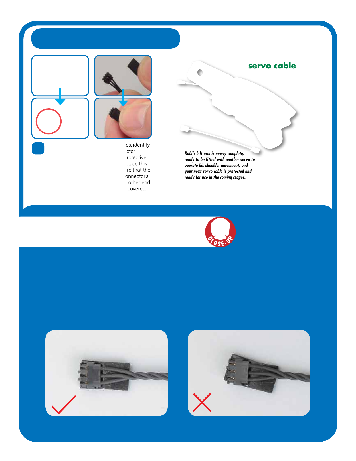
11 As you have done in previous staes, identify
the side of the servo cable’s connector
marked ‘PUSH’. Then, separate a protective
pad from the sheet (Stae 3) and place this
on top of the connector, makin sure that the
pad does not extend beyond the connector’s
tip. Repeat for the connector at the other end
of the servo cable so that both are covered.
Assembled
left arm and
servo cable
Robi’s left arm is nearly complete,
ready to be tted with another servo to
operate his shoulder movement, and
your next servo cable is protected and
ready for use in the coming stages.
By now you will be familiar with the servo cables that connect Robi’s servo
motors, but take a moment to revisit the process of applyin the protective pads
to these. It is important that the pads are fitted neatly and in line with the shape
of the cables’ rectanular connectors, because if fitted incorrectly they can
obstruct the other cables and components of the servos. For some steps, it will
be easier to fit the protective pad after the servo connector is in position – when
this is the case, a Tip box will appear next to the step.
SERVO CABLES
The pad is fitted neatly, in line with the connector. The pad is fitted incorrectly, at an anle to the connector.
93

COMING IN PACK 6
PARTS PROVIDED
The servo that will operate
Robi’s left upper arm.
Stage 19
Add another servo
to Robi’s left arm
PARTS PROVIDED
Components to build up Robi’s shoulder joint,
along with another servo cable.
Stage 20
Build up Robi’s
left shoulder joint
Stage 21
Test Robi’s left
shoulder servo
PARTS PROVIDED
The servo that will perform
the role of Robi’s shoulder.
Stage 22
Continue building
up Robi’s body
PARTS PROVIDED
The next parts of Robi’s body, including
the left body cover and servo horn.
Your next FOUR complete
Stages, as Robi starts to
come to life!
Other De Agostini Robotics manuals


Popular Robotics manuals by other brands


 Programming manual")


Eddyfi Technologies
Eddyfi Technologies Inuktun VT150 Vertical Crawler user manual

SunFounder
SunFounder PiSloth manual

adept technology
adept technology 550 Instruction handbook

Lynxmotion
Lynxmotion AL5D-PLTW Guide

Segway Robotics
Segway Robotics RMP 440 Omni V3 user manual

HEBI Robotics
HEBI Robotics 7-DoF Assembly instructions