ABB IRB 910SC Owner's manual

ROBOTICS
Product specification
IRB 910SC

Trace back information:
Workspace 20C version a3
Checked in 2020-09-14
Skribenta version 5.3.075

Product specification
IRB 910SC-3/0.45
IRB 910SC-3/0.55
IRB 910SC-3/0.65
IRC5
Document ID: 3HAC056431-001
Revision: G
© Copyright 2016-2020 ABB. All rights reserved.
Specifications subject to change without notice.

The information in this manual is subject to change without notice and should not
be construed as a commitment by ABB. ABB assumes no responsibility for any errors
that may appear in this manual.
Except as may be expressly stated anywhere in this manual, nothing herein shall be
construed as any kind of guarantee or warranty by ABB for losses, damage to persons
or property, fitness for a specific purpose or the like.
In no event shall ABB be liable for incidental or consequential damages arising from
use of this manual and products described herein.
This manual and parts thereof must not be reproduced or copied without ABB's
written permission.
Keep for future reference.
Additional copies of this manual may be obtained from ABB.
Original instructions.
© Copyright 2016-2020 ABB. All rights reserved.
Specifications subject to change without notice.

Table of contents
7Overview of this specification ..........................................................................................................
91 Description
91.1 Structure ......................................................................................................... 91.1.1 Introduction to structure ........................................................................... 111.1.2 The robot ............................................................................................... 141.2 Standards ........................................................................................................ 141.2.1 Applicable standards ............................................................................... 161.3 Installation ....................................................................................................... 161.3.1 Introduction to installation ......................................................................... 171.3.2 Operating requirements ............................................................................ 181.3.3 Mounting the manipulator ......................................................................... 201.4 Load diagrams .................................................................................................. 201.4.1 Introduction to load diagram ...................................................................... 211.4.2 Load diagram ......................................................................................... 241.4.3 Maximum load and moment of inertia .......................................................... 261.4.4 Extra loads ............................................................................................. 271.5 Mounting of equipment ....................................................................................... 291.6 Calibration ....................................................................................................... 291.6.1 Calibration methods ................................................................................. 311.6.2 Fine calibration ....................................................................................... 321.6.3 Absolute Accuracy option ......................................................................... 341.7 Maintenance and troubleshooting ......................................................................... 341.7.1 Introduction to maintenance and trouble shooting ......................................... 351.8 Robot motion .................................................................................................... 361.8.1 Working range and type of motion .............................................................. 401.8.2 Performance according to ISO 9283 ............................................................ 411.8.3 Velocity ................................................................................................. 421.8.4 Robot stopping distances and times ........................................................... 431.9 Customer connections .......................................................................................
452 Specification of variants and options
452.1 Introduction to variants and options ...................................................................... 462.2 Manipulator ...................................................................................................... 482.3 Floor cables ..................................................................................................... 492.4 User documentation ..........................................................................................
513 Accessories
53Index
Product specification - IRB 910SC 5
3HAC056431-001 Revision: G
© Copyright 2016-2020 ABB. All rights reserved.
Table of contents

This page is intentionally left blank

Overview of this specification
About this product specification
It describes the performance of the manipulator or a complete family of manipulators
in terms of:
• The structure and dimensional prints
• The fulfilment of standards, safety and operating requirements
• The load diagrams, mounting of extra equipment, the motion and the robot
reach
• The specification of variants and options available
Usage
Product specifications are used to find data and performance about the product,
for example to decide which product to buy. How to handle the product is described
in the product manual.
Users
It is intended for:
• Product managers and product personnel
• Sales and marketing personnel
• Order and customer service personnel
References
Documentation referred to in the manual, is listed in the table below.
Document IDDocument name
3HAC056430-001Product manual - IRB 910SC
3HAC056433-001Product manual, spare parts - IRB 910SC
Document IDReference to the circuit diagram for the robot.
3HAC035738-001Product manual - IRC5 Compact
3HAC050941-001Operating manual - IRC5 with FlexPendant
3HAC050945-001Product specification - Controller software IRC5
3HAC047400-001Product specification - Controller IRC5
3HAC052355-001Product specification - Robot user documentation, IRC5 with Robot-
Ware 6
Revisions
DescriptionRevision
First edition.-
Continues on next page
Product specification - IRB 910SC 7
3HAC056431-001 Revision: G
© Copyright 2016-2020 ABB. All rights reserved.
Overview of this specification

DescriptionRevision
• The force and torque values under endurance load and maximum
load have been updated. See Floor mounted on page 18.
• Ball screw spline unit is added to the warning listing the parts that
are easily damaged due to overload. See Information on page 20.
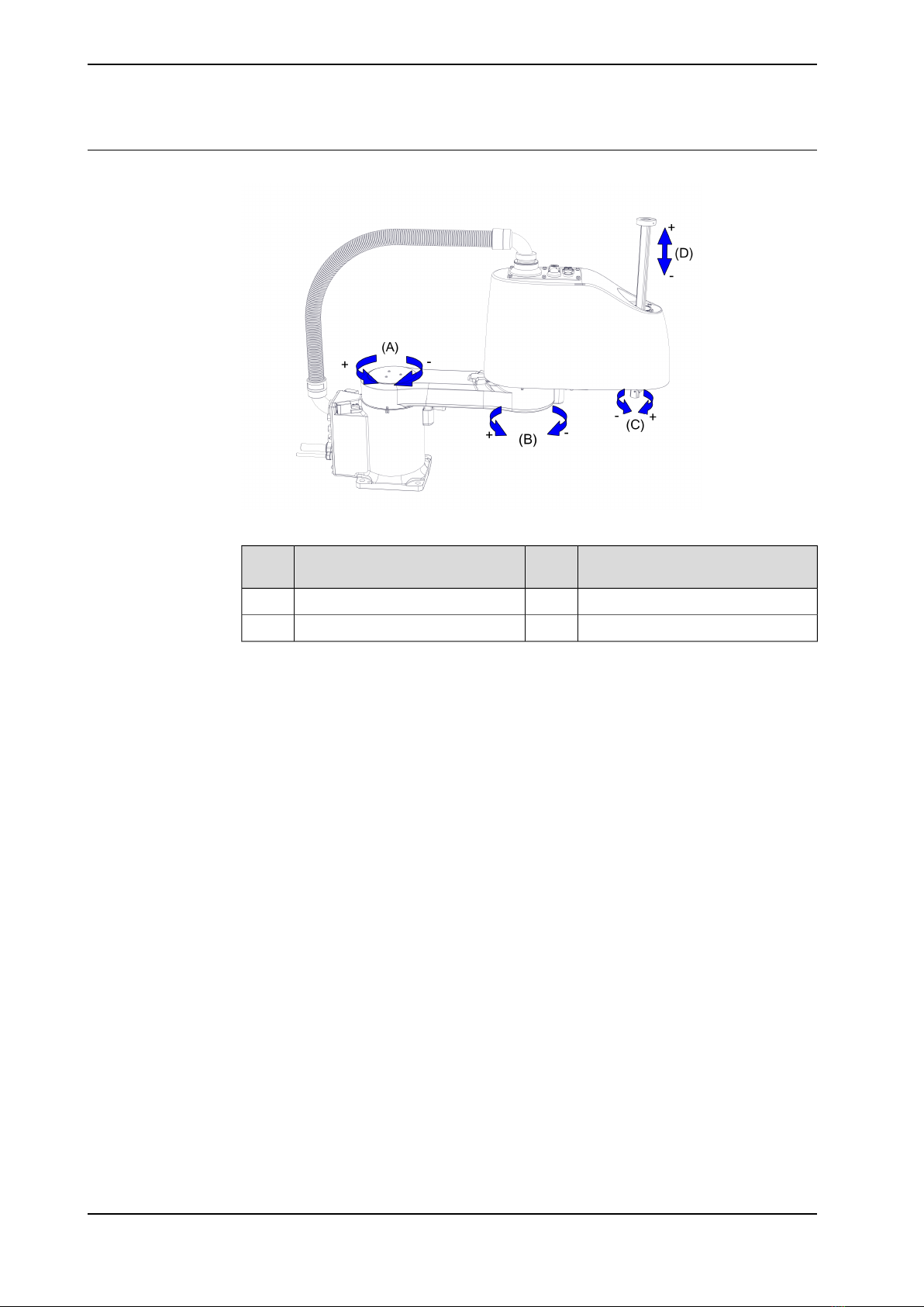
• Working range of axis 4 has been updated. See Robot motion on
page 36.
•Performance data of IRB 910SC-3/0.45 and IRB 910SC-3/0.65 has
been added. See Performance according to ISO 9283 on page 40.
• Velocity of axis 3 changes from 1.02 m/s to 1 m/s. See Velocity
on page 41.
• Minor changes.
A
Published in release R16.2. The following updates are done in this revi-
sion:
• Dimension drawing for fitting the end effector is updated. See
Fitting of end effector to the ball screw spline shaft on page 27.
B
Published in release R17.1. The following updates are done in this revi-
sion:
• Restriction of load diagram added.
• Changed protection from IP30 to IP20
C
Published in release R17.2. The following updates are done in this revi-
sion:
• Updated list of applicable standards.
• Improved picture of end effector dimension.
D
Published in release R18.2. The following updates are done in this revi-
sion:
• Updated the COG figure for describing max. moment of inertia.
E
Published in release R19D The following updates are done in this revi-
sion:
• Updated information about Absolute Accuracy.
• The graphic of working range changed.
F
Published in release R20C The following updates are done in this revi-
sion:
• Add section Extra loads.
G
8 Product specification - IRB 910SC
3HAC056431-001 Revision: G
© Copyright 2016-2020 ABB. All rights reserved.
Overview of this specification
Continued

1 Description
1.1 Structure
1.1.1 Introduction to structure
General
The IRB 910SC is ABB Robotics first generation SCARA robot, with 4 axes and a
rated payload of 3 kg (maximum payload of 6 kg) in three different reach variants
0.45 m, 0.55 m, and 0.65 m, designed specifically for manufacturing industries that
use flexible robot-based automation, e.g. 3C industry. The robot has an open
structure that is especially adapted for flexible use, and can communicate
extensively with external systems.
Operating system
The robot is equipped with the IRC5 Compact (IRC5C) controller and robot control
software, RobotWare. RobotWare supports every aspect of the robot system, such
as motion control, development and execution of application programs,
communication etc. See Product specification - Controller IRC5 with FlexPendant
(IRC5C included).
Safety
The safety standards are valid for the complete robot, manipulator and controller.
Additional functionality
For additional functionality, the robot can be equipped with optional software for
application support - for example dispensing and cutting, communication features
- network communication - and advanced functions such as multitasking, sensor
control etc. For a complete description on optional software, see Product
specification - Controller software IRC5.
Continues on next page
Product specification - IRB 910SC 9
3HAC056431-001 Revision: G
© Copyright 2016-2020 ABB. All rights reserved.
1 Description
1.1.1 Introduction to structure

Manipulator axes
xx1500002631
DescriptionPosi-
tion
DescriptionPosi-
tion
Axis 2BAxis 1A
Axis 3DAxis 4C
10 Product specification - IRB 910SC
3HAC056431-001 Revision: G
© Copyright 2016-2020 ABB. All rights reserved.
1 Description
1.1.1 Introduction to structure
Continued

1.1.2 The robot
General
The IRB 910SC is available in three versions and all can only be mounted on floor
or other flat surface, no other mounting position is permitted.
Reach (m)Maximum handling ca-
pacity (kg)
Rated handling capacity
(kg)
Robot type
0.45 m6 kg3 kgIRB 910SC
0.55 m6 kg3 kgIRB 910SC
0.65 m6 kg3 kgIRB 910SC
Manipulator weight
WeightData
24.5 kgIRB 910SC-3/0.45
25 kgIRB 910SC-3/0.55
25.5 kgIRB 910SC-3/0.65
Other technical data
NoteDescriptionData
< 70 dB (A) Leq (acc. to the work-
ing space Machinery directive
2006/42/EG)
The sound pressure level outsideAirborne noise level
Power consumption
IRB 910SC-
3/0.65
IRB 910SC-
3/0.55
IRB 910SC-
3/0.45
Robot in 0 degree position
71 W71 W71 WBrakes engaged
127.6 W127.6 W127.6 WBrakes disengaged
Continues on next page
Product specification - IRB 910SC 11
3HAC056431-001 Revision: G
© Copyright 2016-2020 ABB. All rights reserved.
1 Description
1.1.2 The robot

Dimensions
xx1500002526
VariantDescriptionItem
IRB 910SC-
3/0.65
IRB 910SC-
3/0.55
IRB 910SC-
3/0.45
400 mm300 mm200 mmLength of lower armL
620 mm620 mm620 mmMaximum heightA
Continues on next page
12 Product specification - IRB 910SC
3HAC056431-001 Revision: G
© Copyright 2016-2020 ABB. All rights reserved.
1 Description
1.1.2 The robot
Continued

VariantDescriptionItem
IRB 910SC-
3/0.65
IRB 910SC-
3/0.55
IRB 910SC-
3/0.45
180 mm180 mm180 mmZ strokeB
Product specification - IRB 910SC 13
3HAC056431-001 Revision: G
© Copyright 2016-2020 ABB. All rights reserved.
1 Description
1.1.2 The robot
Continued

1.2 Standards
1.2.1 Applicable standards
Note
The listed standards are valid at the time of the release of this document. Phased
out or replaced standards are removed from the list when needed.
General
The product is designed in accordance with EN ISO 10218-1, Robots for industrial
environments - Safety requirements -Part 1 Robot. If there are deviations, these
are listed in the declaration of incorporation which is included on delivery.
Standards, EN ISO
The product is designed in accordance with selected parts of:
DescriptionStandard
Safety of machinery - General principles for design - Risk as-
sessment and risk reduction
EN ISO 12100:2010
Safety of machinery, safety related parts of control systems -
Part 1: General principles for design
EN ISO 13849-1:2015
Safety of machinery - Emergency stop - Principles for designEN ISO 13850:2015
Robots and robotic devices -- Coordinate systems and motion
nomenclatures
ISO 9787:2013
Manipulating industrial robots, performance criteria, and related
test methods
ISO 9283:1998
Classification of air cleanlinessEN ISO 14644-1:2015i
Ergonomics of the thermal environment - Part 1EN ISO 13732-1:2008
EMC, Generic emissionEN 61000-6-4:2007 +
A1:2011
IEC 61000-6-4:2006 +
A1:2010
(option 129-1)
EMC, Generic immunityEN 61000-6-2:2005
IEC 61000-6-2:2005
Arc welding equipment - Part 1: Welding power sourcesEN IEC 60974-1:2012ii
Arc welding equipment - Part 10: EMC requirementsEN IEC 60974-10:2014ii
Safety of machinery - Electrical equipment of machines - Part
1 General requirements
EN IEC 60204-1:2016
Degrees of protection provided by enclosures (IP code)IEC 60529:1989 + A2:2013
iOnly robots with protection Clean Room.
ii Only valid for arc welding robots. Replaces EN IEC 61000-6-4 for arc welding robots.
Continues on next page
14 Product specification - IRB 910SC
3HAC056431-001 Revision: G
© Copyright 2016-2020 ABB. All rights reserved.
1 Description
1.2.1 Applicable standards

Deviation for delay circuit
Some variants of IRB 910SC has an inherent delay circuit to enhance the lifetime
of speed reducers. This only applies to variants IRB 910SC-3/0.45, IRB
910SC-3/0.55, and IRB 910SC-3/0.65.
This circuit allows an extended time period for soft stop by enabling a delay of
about 0.5 s before motor brakes are engaged, e.g. when the three-position enabling
device is released or compressed, or the emergency stop is pressed. During this
period, the robot axes 1 and 2 will continue their movement until they are stopped
by the motor or eventually by brakes. Make sure the robot safeguarded area is
free from obstacles, even during manual operations. Note that this delay does not
apply to axes 3 and 4.
For more details regarding stopping time and distance metric, see Product
specification - Robot stopping distances according to ISO 10218-1.
European standards
The product is designed in accordance with selected parts of:
DescriptionStandard
Safety of machinery - Ergonomic design principles - Part 1:
Terminology and general principles
EN 614-1:2006 + A1:2009
Safety of machinery - Two-hand control devices - Functional
aspects - Principles for design
EN 574:1996 + A1:2008
UL, ANSI, and other standards
DescriptionStandard
Safety requirements for industrial robots and robot systemsANSI/RIA R15.06
Safety standard for robots and robotic equipmentANSI/UL 1740
Industrial robots and robot Systems - General safety require-
ments
CAN/CSA Z 434-14
Product specification - IRB 910SC 15
3HAC056431-001 Revision: G
© Copyright 2016-2020 ABB. All rights reserved.
1 Description
1.2.1 Applicable standards
Continued

1.3 Installation
1.3.1 Introduction to installation
General
IRB 910SC is adapted for normal industrial environment. An end effector with max.
weight of 6 kg, including payload, can be mounted on the lower end of the ball
screw spline shaft (axis 3). For more information about mounting of extra equipment,
see Mounting of equipment on page 27.
16 Product specification - IRB 910SC
3HAC056431-001 Revision: G
© Copyright 2016-2020 ABB. All rights reserved.
1 Description
1.3.1 Introduction to installation

1.3.2 Operating requirements
Protection standard
Protection standard IEC529Robot variant
IP20All variants, manipulator
Explosive environments
The robot must not be located or operated in an explosive environment.
Working range limitations
EPS will not be selectable and no mechanical limitations available.
Ambient temperature
TemperatureStandard/OptionDescription
+ 5°C i(41°F) to + 45°C (113°F)StandardManipulator during opera-
tion
See Product specification - Control-
ler IRC5
Standard/OptionFor the controller
- 25°C (-13°F) to + 55°C (131°F)StandardComplete robot during
transportation and storage
up to + 70°C (158°F)StandardFor short periods (not ex-
ceeding 24 hours)
iAt low environmental temperature < 10ºC is, as with any other machine, a warm-up phase
recommended to be run with the robot. Otherwise there is a risk that the robot stops or run with
lower performance due to temperature dependent oil and grease viscosity.
Relative humidity
Relative humidityDescription
Max. 95% at constant temperatureComplete robot during operation, transportation and
storage
Product specification - IRB 910SC 17
3HAC056431-001 Revision: G
© Copyright 2016-2020 ABB. All rights reserved.
1 Description
1.3.2 Operating requirements

1.3.3 Mounting the manipulator
General
Maximum load in relation to the base coordination system. See Figure below.
Floor mounted
Max. load (emergency stop)Endurance load (in operation)Force
±945 N±651 NForce xy
255±441 N255±392 NForce z
±418 Nm±260 NmTorque xy
±238 Nm±121 NmTorque z
The illustration shows the directions of the robots stress forces.
xx1500002522
Force in any direction in the XY planeFxy
Force in the Z planeFz
Bending torque in any direction in the XY planeTxy
Bending torque in the Z planeTz
The table shows the various forces and torques working on the robot during different
kinds of operation.
Note
These forces and torques are extreme values that are rarely encountered during
operation. The values also never reach their maximum at the same time!
Continues on next page
18 Product specification - IRB 910SC
3HAC056431-001 Revision: G
© Copyright 2016-2020 ABB. All rights reserved.
1 Description
1.3.3 Mounting the manipulator

Fastening holes robot base
View from top.
xx1500002521
Attachment bolts, specification
The table specifies the type of securing screws and washers to be used to secure
the robot directly to the foundation. It also specifies the type of pins to be used.
M10x25Suitable screws
4 pcsQuantity
8.8Quality
20x10.5x2Suitable washer
2 pcs, D6x20, ISO 2338 - 6m6x20 - A1Guide pins
45 NmTightening torque
0.1
xx1500000627
Level surface requirements
Product specification - IRB 910SC 19
3HAC056431-001 Revision: G
© Copyright 2016-2020 ABB. All rights reserved.
1 Description
1.3.3 Mounting the manipulator
Continued

1.4 Load diagrams
1.4.1 Introduction to load diagram
Information
WARNING
It is very important to always define correct actual load data and correct payload
of the robot. Incorrect definitions of load data can result in overloading of the
robot.
If incorrect load data and/or loads are outside load diagram is used the following
parts can be damaged due to overload:
• ball screw spline unit
• motors
• gearboxes
• mechanical structure
WARNING
In the robot system is the service routine LoadIdentify available, which allows
the user to make an automatic definition of the tool and load, to determine correct
load parameters. For detailed information, see Operating manual - IRC5 with
FlexPendant.
WARNING
Robots running with incorrect load data and/or with loads outside diagram, will
not be covered by robot warranty.
General
The load diagram includes a nominal pay load inertia, J0of 0.01 kgm2. At different
moment of inertia the load diagram will be changed. For robots that are allowed
tilted, wall or inverted mounted, the load diagrams as given are valid.
20 Product specification - IRB 910SC
3HAC056431-001 Revision: G
© Copyright 2016-2020 ABB. All rights reserved.
1 Description
1.4.1 Introduction to load diagram
Table of contents
Other ABB Robotics manuals

ABB
ABB IRB 6620LX User manual

ABB
ABB M98 Product manual

ABB
ABB IRB 7600 - 500/2.55 User manual

ABB
ABB IRB 6620 - 150/2.2 User manual

ABB
ABB IRB 660 User manual

ABB
ABB IRB 930 User manual

ABB
ABB IRB 6640 - 180/2.55 User manual

ABB
ABB 180 Comfort User manual

ABB
ABB IRB 7600 User manual

ABB
ABB IRB 1200 Owner's manual

ABB
ABB M2004 User instructions

ABB
ABB IRB 1200 User manual

ABB
ABB IRB 1400 User manual

ABB
ABB IRB 1600 - 5/1,2 type A User manual

ABB
ABB IRB 140 User manual

ABB
ABB IRB1410 User manual

ABB
ABB IRB 7600 - 500/2.55 User manual

ABB
ABB IRB 660 Owner's manual

ABB
ABB IRB6400 Programming manual

ABB
ABB IRB 910INV User manual