deconta green dec G 50 User guide

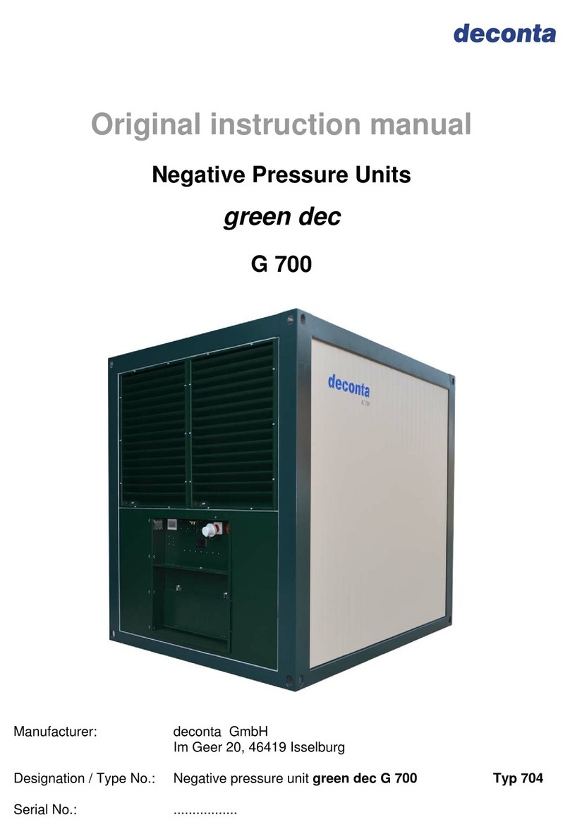
Original instruction manual
Negative Pressure Units
green dec
G 50 / G 55
G 100
G 200
G 300
G 400
G 500
deconta GmbH - Im Geer 20 - 46419 Isselburg

Instruction Manual
Negative Pressure Unit green dec
Version 1 Page 2
Table of contents
1.Basic safety advice............................................................................................................4
1.1.Intended use....................................................................................................................................5
1.2.Dangers ...........................................................................................................................................6
2.Transport and storage.......................................................................................................7
2.1.Delivery............................................................................................................................................7
2.2.Transport..........................................................................................................................................7
2.3.Storage ............................................................................................................................................7
3.Delivery contents ...............................................................................................................8
4.Technical data....................................................................................................................9
4.1.Performance data G 50 / G 55 ........................................................................................................9
4.2.Performance data G 100 .................................................................................................................9
4.3.Performance data G 200 ...............................................................................................................10
4.4.Performance data G 300 ...............................................................................................................10
4.5.Performance data G 400 ...............................................................................................................11
4.6.Performance data G 500 ...............................................................................................................11
4.7.Connections, dimensions, weights ................................................................................................12
4.8.Filter description / classification.....................................................................................................13
5.Technical description ......................................................................................................15
5.1.Unit description..............................................................................................................................15
5.2.Control SE......................................................................................................................................16
5.3.Control SRE +................................................................................................................................16
5.4.Control SRE connect.....................................................................................................................17
6.Assembly instruction.......................................................................................................18
7.Initial operation ................................................................................................................19
7.1.Control SE......................................................................................................................................19
7.1.1.Room pressurisation..............................................................................................................19
7.2.Control SRE +................................................................................................................................20
7.2.1.Set display language .............................................................................................................21
7.2.2.Language table......................................................................................................................22
7.2.3.Manual mode.........................................................................................................................25
7.2.4.Automatic operation negative pressure.................................................................................26
7.2.5.Automatic operation volume flow...........................................................................................28
7.2.6.Changing operation mode .....................................................................................................30
7.2.7.Stand-by mode ......................................................................................................................31
7.2.8.Filter sensor...........................................................................................................................33
7.2.9.Additional settings..................................................................................................................34
7.2.10.Warnings and indications.......................................................................................................35
7.3.Control SRE connect.....................................................................................................................36
7.3.1.Create your user account ......................................................................................................37
7.3.2.Add the device to your user account.....................................................................................38
7.3.3.Manual mode.........................................................................................................................41
7.3.4.Automatic mode.....................................................................................................................42
7.3.5.Day / Night setting .................................................................................................................43
7.3.6.Stand-by mode ......................................................................................................................43
7.3.7.Consumption..........................................................................................................................44
7.3.8.Dust sensor............................................................................................................................44

Instruction Manual
Negative Pressure Unit green dec
Version 1 Page 3
7.3.9.Service...................................................................................................................................45
7.3.10.Software packages................................................................................................................46
7.3.11.Device information.................................................................................................................47
7.3.12.Alarms....................................................................................................................................47
7.3.13.Turn off the device.................................................................................................................49
8.Maintenance .....................................................................................................................50
8.1.Information on filter change...........................................................................................................50
8.1.1.Control SE..............................................................................................................................50
8.1.2.Control SRE +........................................................................................................................51
8.1.3.Control SRE connect.............................................................................................................52
8.2.Filter change..................................................................................................................................53
9.Possible disturbances and their elimination.................................................................57
10.Options / special versions...............................................................................................58
10.1.Double filtration..............................................................................................................................58
11.Sound level measurement...............................................................................................59
12.Declaration of Conformity...............................................................................................60

Instruction Manual
Negative Pressure Unit green dec
Version 1 Page 4
The copyright of this instruction manual remains with deconta. This manual is intended for assembly,
operation and maintenance personnel. It contains instructions and drafts of technical nature which may
neither be distributed nor used in any unauthorised way for competitive purposes or passed on to others.
1.Basic safety advice
Dealing with the device technology is only permitted for trained competent personnel.
Exact knowledge of the manual is a necessary requirement for the staff when handling the
device.
The operating instructions should always be kept in the immediate vicinity, accessible to
all persons.
deconta must oblige you, as operator of the device, to follow the operating instructions
and to use the device technology only as intended and not in an inappropriate manner! In
case of non-compliance, deconta assumes no liability.
To ensure safety during operation of the device, please strictly observe the following:
• Do not use in potentially explosive atmospheres.
• Maintenance, including removal and replacement of the filters, should only be
carried out authorized personnel wearing appropriate protective clothing.
• For all repair and maintenance work, the unit must be completely disconnected from the
power supply.
• The safety and protective equipment must be in perfect working order.
• Safety instructions affixed to the device are to be left in readable condition and to be
followed.
• General, legal and other binding regulations and procedures for accident prevention
and handling of hazardous substances must be observed.
To ensure safety, modifications to the device are not permitted.
To avoid damage, never operate the unit without built-in filters.
ATTENTION!
The negative pressure units are not suitable for use in condensing, corrosive,
flammable and explosive atmospheres.
We explicitly refer to the additional regional and national safety measures and
regulations when operating the device technology.
The operator must carry out the inspection of the exhaust air at initial acceptance as well
as at least a 3-year interval.
In addition to the instruction manual, general, legal and other binding regulations on
accident prevention and environmental protection must be observed.

Instruction Manual
Negative Pressure Unit green dec
Version 1 Page 5
1.1.Intended use
The negative pressure unit is designed for filtering non-condensing, asbestos-
contaminated room air, in the temperature range up to +45 ° C, with exhaust air discharged
to atmosphere.
In the case of asbestos removal work within contaminated areas, it is expected that
airborne asbestos fibres will escape the contaminated area and pose a risk to human
health and environment. For these reasons, contaminated areas are separated from the
asbestos-free areas and kept under dynamic negative pressure by means of negative
pressure units.
An integrated filter system reduces the airborne asbestos fiber concentration to a figure of
max. 1000F/m
3
in the exhaust air. The exhaust air is expelled to the open air.
The device is not suitable for filtering flammable gases or dusts.
The user must comply with the specified operating parameters of this manual.
The device may only be used according to its intended use. Any further use beyond this is
not intended. The user is liable for any damages or injuries of any kind whatsoever.
ATTENTION! The device was only tested with original deconta HEPA filters H13 and
original deconta HEPA filters H14. To ensure machine safety, only original deconta
filters should be used. The machine safety cannot be guaranteed if this is not
observed. This may result in the risk of hazardous substances being released into
the environment due to a filter overload (leakage, filter crack, ...) in an unintentional
and uncontrolled manner.
Tested deconta HEPA filter:
Device HEPA filter H13
Article No. HEPA filter H14
Article No.
G 50 AU1499
G 55 AU3663 AU3664
G 100 AU2093
AU3723 AU1888
G 200 AU1052
AU3722 AU3496
G 300 AU619
AU3721 AU3575
G 400 AU1044
AU3720 AU3788
G 500

Instruction Manual
Negative Pressure Unit green dec
Version 1 Page 6
1.2.Dangers
DANGER
Electric shock due to faulty mains cable.
Touching a defective mains cable may result in death or serious injury.
Do not damage the mains cable (e.g. by vehicle overrun, tearing, squeezing).
Regularly check the mains cable for damage.
Have defective mains cable replaced before use by the deconta service or a
qualified electrician.
CAUTION
Damage due to unsuitable mains voltage.
The device can be damaged if it is connected to an unsuitable mains voltage.
Check whether the voltage indicated on the rating plate matches the local mains
voltage.
WARNING
Hazardous materials.
The following materials must not be filtered:
Hot materials (glowing cigarettes, hot ash, etc.)
Combustible, explosive, aggressive materials and dusts
WARNING
Contaminated filters.
Filter changes may only be carried out by authorised persons who carry suitable
protective clothing.
Dispose of the filter according to the legal requirements.

Instruction Manual
Negative Pressure Unit green dec
Version 1 Page 7
2.Transport and storage
2.1.Delivery
The negative pressure unit is delivered on a pallet. To protect against weather influences
and damage during transport, the device is wrapped in a plastic film.
Transport damage must be immediately documented following delivery by the supplier.
Please note any damages on the consignment note.
2.2.Transport
Only transport the device in a clean decontaminated condition.
For lifting above obstacles, carry handles are located on the device.
2.3.Storage
Store the unit in a decontaminated condition.
To avoid damage, the device should only be stored in a clean dry inaccessible rooms
intended for unauthorised persons only.
Close the intake manifold with the transport lid and the air vent with the plug.

Instruction Manual
Negative Pressure Unit green dec
Version 1 Page 8
3.Delivery contents
Included in the delivery contents of a negative pressure unit, independent of whether a
device has been purchased or rented, unless other agreements have been made:
Negative Pressure Unit
Instruction manual
Transport lid
Plug
Packaging
Return after the end of the rental period
For the protection of our customers and in the sense of dangerous goods transport
regulations, we must insist on the following conditions of return:
As listed above
Thoroughly cleaned (ready for use)
Free from any adhesive residues
Without residual fiber bonding agent
Without filters
Without damages

Instruction Manual
Negative Pressure Unit green dec
Version 1 Page 9
4.Technical data
4.1.Performance data G 50 / G 55
110 V 230 V
Air performance, free-blowing max. 1500 m³/h 1500 m³/h
+ deconta H13 max. 1100 m³/h 1100 m³/h
+ pre-filter (EU4) max. 1000 m³/h 1000 m³/h
Power connection 100 - 120 V 230 V
Power consumption 3 A 1,2 A
Motor power 0,17 kW 0,17 kW
Power cable type H07RN-F 3G1,5
Protection class I
Type of protection IP 54
Filter system 2-stage
- pre-filter EU
- HEPA filter acc. to EN 1822 class H13
4.2.Performance data G 100
110 V 230 V
Air performance, free-blowing max. 2000 m³/h 2300 m³/h
+ deconta H13 or H14 filter
max. 1500 m³/h 1800 m³/h
+ pre- and intermediate filter
(EU3, EU4) max. 1350 m³/h 1650 m³/h
Power connection 100 - 120 V 230 V
Power consumption 4 A 2,5 A
Motor power 0,345 kW 0,5 kW
Power cable type H07RN-F 3G1,5
Protection class I
Type of protection IP 54
Filter system 3-stage
- pre-filter EU 3
- intermediate filter EU4
- HEPA filter acc. to EN 1822 class H13 or H14

Instruction Manual
Negative Pressure Unit green dec
Version 1 Page 10
4.3.Performance data G 200
110 V 230 V
Air performance, free-blowing max. 4000 m³/h 4500 m³/h
+ deconta H13 or H14 filter
max. 3050 m³/h 3400 m³/h
+ pre- and intermediate filter
(EU3, EU4) max. 2500 m³/h 3000 m³/h
Power connection 100 - 120 V 230 V
Power consumption 7 A 4 A
Motor power 2x 0,345 kW 0,75 kW
Power cable type H07RN-F 3G1,5
Protection class I
Type of protection IP 54
Filter system 3-stage
- pre-filter EU 3
- intermediate filter EU4
- HEPA filter acc. to EN 1822 class H13 or H14
4.4.Performance data G 300
110 V 230 V
Air performance, free-blowing max. 7400 m³/h 8000 m³/h
+ deconta H13 or H14 filter
max. 5150 m³/h 5700 m³/h
+ pre- and intermediate filter
(EU3, EU4) max. 4000 m³/h 5150 m³/h
Power connection 100 - 120 V 230 V
Power consumption 15 A 8 A
Motor power 4x 0,345 kW 1,5 kW
Power cable type H07RN-F 3G2,5 H07RN-F 3G1,5
Protection class I
Type of protection IP 54
Filter system 3-stage
- pre-filter EU 3
- intermediate filter EU4
- HEPA filter acc. to EN 1822 class H13 or H14

Instruction Manual
Negative Pressure Unit green dec
Version 1 Page 11
4.5.Performance data G 400
Air performance, free-blowing max. 9500 m³/h
+ deconta H13 or H14 filter
max. 8400 m³/h
+ pre- and intermediate filter
(EU3, EU4) max. 7800 m³/h
Power connection 400 V
Power consumption 5 A
Motor power 1,5 kW
Power cable type 16A CEE CEE add-on-device-connector
Protection class I
Type of protection IP 54
Filter system 3-stage
- pre-filter EU 3
- intermediate filter EU4
- HEPA filter acc. to EN 1822 class H13 or H14
4.6.Performance data G 500
Air performance, free-blowing max. 15400 m³/h
+ deconta H13 or H14 filter
max. 13400 m³/h
+ pre- and intermediate filter
(EU3, EU4) max. 12800 m³/h
Power connection 400 V
Power consumption 5 A
Motor power 5,7 kW
Power cable type 16A CEE CEE add-on-device-connector
Protection class I
Type of protection IP 54
Filter system 3-stage
- pre-filter EU 3
- intermediate filter EU4
- HEPA filter acc. to EN 1822 class H13 or H14

Instruction Manual
Negative Pressure Unit green dec
Version 1 Page 12
4.7.Connections, dimensions, weights
G 50 G 55 G 100 G 200 G 300 G 400 G 500
Fan unit Filter unit
FG 500
Hose connection
exhaust air option 300 450 450 450 450
Hose connection
suction option option option option 2x 450 option
Length in mm 525 770 970 1150 1200 1180 715
Width in mm 390 410 410 720 720 785 720
Height in mm 390 410 840 840 1150 955 1150
Weight incl. filter
in kg 18,8 19 27,5 55 79 105 148 63

Instruction Manual
Negative Pressure Unit green dec
Version 1 Page 13
4.8.Filter description / classification
Integrated in the device is a 3-stage filter combination (G 50 only 2-stages).
In particular:
Pre-filter and intermediate filter Pre-filter Intermediate filter
Quality class acc. to DIN 24185 / EN 779 G3 / EU3 G4 / EU4
Frame Cardboard frame,
47 mm wide Cardboard frame,
47 mm wide
Filter medium Glas fibre Synthetic
Degree of separation (Am) 85 % 90 %
Nominal volume flow 5400m³/h/m² 5400m³/h/m²
Nominal flow velocity at nominal volume 1,5 m/s 1,5 m/s
Initial pressure drop 30 Pa 42 Pa
Recommended final pressure drop 450 Pa 250 Pa
Temperature / humidity 100°C/100% RH
(relative humidity)
100°C/100% RH
(relative humidity)
Filter dimensions (in mm):
G 50 / G 55
G 100
G 200
G 300
G 400
G 500
305 x 305 x 47
305 x 610 x 47
610 x 610 x 47
610 x 910 x 47
610 x 910 x 47
305 x 305 x 47
305 x 305 x 47
305 x 610 x47
610 x 610 x47
610 x 910 x 47
610 x 910 x 47

Instruction Manual
Negative Pressure Unit green dec
Version 1 Page 14
HEPA filter
Frame Plastic
Filter medium Micro fiberglass paper
Casting compound Polyurethane
Seal Polyurethane
Filter class H13 or H 14 acc. to EN 1822
Temperature / humidity 70°C/100% RH
(relative humidity)
Filter dimensions (in mm):
G 50
G 55
G 100
G 200
G 300
G 400
G 500
284 x 284 x 150
305 x 305 x 150
305 x 305 x 292
305 x 610 x 292
610 x 610 x 292
610 x 910 x 292
610 x 910 x 292
Grip protection Double-sided

Instruction Manual
Negative Pressure Unit green dec
Version 1 Page 15
5.Technical description
5.1.Unit description
Negative Pressure Unit for filtering asbestos-contaminated room air via a 3-stage filter unit
(G 50 only 2-stages). The built-in HEPA filter meets the requirements of EN 1822 class
H13 or H14.
Energy-efficient and performance-optimized fan with high-capacity
Smooth and easy-to-decontaminate housing
Light and sturdy housing
Threefold sealed HEPA filter
HEPA filter acc. to EN 1822 class H13 or H14
Easy, very low-emission filter change in 3 minutes
Filter change is indicated optically via a manometer (only for SE)
Stainless steel and powder coated housing
Stepless power control 0 - 100%
Automatic soft start, even after power failure
All operating control and functional elements are shock-protected
Automatically closing exhaust flaps
Options:
Mounting housing for second HEPA filter (double filtration)
Mounting housing for bag filter
Chassis (only G 50 / G 55 and G 100)
Hose connection adapter

Instruction Manual
Negative Pressure Unit green dec
Version 1 Page 16
The control of the Negative Pressure Unit (NPU) is optionally available in the following
versions:
5.2.Control SE
For power regulation, NPU is supplied with a manual speed controller.
5.3.Control SRE +
For power regulation, the NPU is supplied with a PLC control via a touch display in order
to measure and regulate the negative pressure or the volume flow.
The negative pressure is measured between the contaminated area and a reference point
(adjoining rooms) to be defined and is kept at the set point by continuous speed control of
the electric fan.
The volumetric flow is measured in the unit and is kept at the set point by continuous speed
control of the electric fan. Manual control is also possible.
The fan power is set using the "+" and "-" keys. In "manual" operation the machine does
not regulate!
The need to replace the HEPA filter is indicated on the NPU display.
A filter sensor monitors the particle concentration in the exhaust air and triggers an optical
and acoustic alarm if a value of 100 particles per liter is permanently exceeded.

Instruction Manual
Negative Pressure Unit green dec
Version 1 Page 17
5.4.Control SRE connect
IoT (Internet of Things) => Devices with SRE connect control can be remotely controlled
and monitored with any internet-enabled computer, mobile phone or tablet.
For power regulation, the negative pressure unit is supplied with a control via a touch
display to measure and regulate the negative pressure and / or the volume flow.
The negative pressure is measured between the black area and a reference point to be
defined (adjacent rooms) and kept at the setpoint value by continuous speed control of
the electric fan.
The volume flow is measured in the device and kept at the setpoint value by continuous
speed control of the electric fan.
A manual control is also possible.
A filter sensor monitors the particle concentration in the exhaust air and triggers a visual
and audible alarm if a value of 100 particles per liter is permanently exceeded.
A necessary filter change is shown on the display.

Instruction Manual
Negative Pressure Unit green dec
Version 1 Page 18
6.Assembly instruction
The Negative Pressure Unit is shipped ready-to-use from the factory and is intended for
immediate commissioning.
In case of visible damage, do not operate the unit.
Please contact deconta GmbH immediately.
Please note:
In principle, the negative pressure unit can also be operated directly in the
contaminated area (overpressure technology prevents the penetration of
contaminated ambient air into the housing).
Since the devices are contaminated from the outside and therefore have to be
cleaned after completion of the rehabilitation, a use in the contaminated area should
absolutely be avoided.
Integrate the device to the partition wall clean/ contaminated area
Insert approx. 100 mm into the contaminated area
Seal the device with the partition wall
Route the exhaust hose into the open air
Ensure adequate supply air in the contaminated area
clean area
contaminated area
supply
air

Instruction Manual
Negative Pressure Unit green dec
Version 1 Page 19
7.Initial operation
7.1.Control SE
For power regulation, the negative pressure unit is supplied with a manual speed controller.
Connect the power supply
Operate the controller
7.1.1. Room pressurisation
Set the required negative pressure at the air intake or at the manual speed controller
negative pressure too high: open air supply or decrease speed controller
negative pressure too low: close air supply or increase speed controller

Instruction Manual
Negative Pressure Unit green dec
Version 1 Page 20
7.2.Control SRE +
Set the measuring point in the contaminated area and connect it to the negative
pressure connection with the PE hose 8 x 1
Determine the measuring point in the clean area (adjoining rooms) and connect to
the atmosphere connection with PE hose 8 x 1
Establish power connection, the following is displayed for approx. 30 seconds
After the initialization, the device is ready for operation. The last saved settings are
automatically set.
connection
atmos
p
häre
connection
negative
pressure
Other manuals for green dec G 50
1
This manual suits for next models
6
Table of contents
Other deconta Water Filtration System manuals
Popular Water Filtration System manuals by other brands

Biorock
Biorock MONOBLOCK-2 Series Installation & user guide

brondell
brondell H630 Cypress owner's manual

EHEIM
EHEIM Aquaball 45 manual

ENVIROGARD
ENVIROGARD Rainfresh SM4 Assembly and operating instructions

Envirovent
Envirovent NitroBox NO2 installation guide

Henden
Henden HMSC20 Installation & owner's manual

Confidence
Confidence RO 300 user manual

Draper
Draper Expert 24338 Original instructions

Frizzlife
Frizzlife TW10 owner's manual

Oase
Oase Filtral 2500 UVC operating instructions

Drinking Fountain Doctor
Drinking Fountain Doctor EFHA8 1G Installation use and care manual

A.O. Smith
A.O. Smith Pro AOW-AS20-R owner's manual