Dectron Dry-O-Tron NG Series User manual

DRY COOLERS
NG SERIES
Dectron.com
OPERATION AND MAINTENANCE MANUAL

Table of Contents
General Information .....................................................................................................................................2
Document Scope........................................................................................................................................................ 2
Operating Safety (Warnings, Cautions, and Notes)................................................................................................... 2
Basic Information....................................................................................................................................................... 4
Operation and Control............................................................................................................................................... 7
Layout and Components...............................................................................................................................9
Basic Maintenance ......................................................................................................................................13
Maintenance and Safety.......................................................................................................................................... 13
Maintenance Key Points .......................................................................................................................................... 14
Airside Coil(s) Cleaning. ........................................................................................................................................... 14
Dry Cooler Service.................................................................................................................................................... 15
Warranty......................................................................................................................................................15
Dectron Dry Cooler OMM 2September 2020
General Information
Document Scope
This manual provides operation and maintenance information about the Dry Cooler and its operation.
Additional information regarding installation, maintenance, and equipment commissioning and auxiliary devices is
provided with the system and can also be obtained from the manufacturer.
Contact Us
Dectron
5685 Rue Cypihot
Saint Laurent QC, H4S1R3
Canada
Dectron.com
1-833-DAS-POOL (327-7665)
Schedule / Modify a Start-up:
Start[email protected]
Inquire about Warranty:
Warranty@DehumidifiedAirServices.com
Order Parts:
All Other Product Support:
Support@DehumidifiedAirServices.com
Operating Safety (Warnings, Cautions, and Notes)
FOR YOUR SAFETY: READ BEFORE PERFORMING ANY OPERATIONS, MAINTENANCE OR SERVICE TASKS!
Only qualified technicians should install, operate, maintain or service mechanical equipment
including current dehumidification system.
Read this manual before performing any tasks to familiarize yourself with the equipment as well
as with any potential hazards. Always exercise caution!
Beware of electrical power and high electrical voltage!
•Follow proper safety procedures – lockout, tagout, and other respective procedures
•Failure to follow safety procedures can result in serious injury or death
Beware of moving parts and hot surfaces!
•Make sure to stop all moving parts (fans, blowers, etc.) before accessing the equipment’s
internal compartments
•Be aware of hot surfaces (hot refrigeration, space heating pipes, coils, heaters, etc.)
Beware of pressures and chemicals!
•Operating equipment may contain glycol-based cooling media mixture under pressure!
September 2020 3Dectron Dry Cooler OMM
The following warnings, cautions, and notes appear throughout this manual and referenced documentation
whenever special care must be taken to avoid potential hazards that could result in equipment malfunction or
damage, personal injury, or death.
WARNING
Indicates a potentially hazardous
situation that could result in
serious injury or death if handled
improperly.
CAUTION
Indicates a potentially hazardous
situation that could result in
moderate injury or equipment
damage if handled improperly.
Note
Indicates a situation that could
result in equipment damage or
improper/ineffective operation if
handled improperly.
Attention: Installation and Service Contractors
WARNING! Any work (installation, start up, service, maintenance, repair, etc.) on any mechanical
equipment (HVAC system, dry cooler, etc.) must be performed in accordance with manufacturer’s
recommendations as well as submittal documentation, local Codes and Regulations, and appropriate field
practices. Failure to do so could result in personal injury, equipment damage or malfunction, and will void
equipment warranty. Only qualified and properly trained individuals should perform tasks on this equipment.
Attention: Maintenance Team
CAUTION. To ensure equipment longevity and proper and efficient operation, this mechanical equipment
should be maintained properly and regularly. Failure to do so could negatively affect system performance. It
could also lead to equipment damage, malfunction, premature wear and tear and may void equipment warranty.
Dectron Dry Cooler OMM 4September 2020
Basic Information
View and Options
The views of standard NG series dry coolers are shown on
Pic.C.1. and C.2 below.
Dry cooler Options
•Capacity. NG series dry coolers range broadly in their
capacities, which depends on factors including physical
size, fluid flow rate, glycol concentration and ambient
conditions. See submittal for specific capacity of your
equipment.
•Coils and Fans - single and multi fan and coil combo.
oPic. C.1 shows single fan dry coolers: NG-Z, NG-
V-01 and -02 are “single fan – single coil” type,
NG-V-11 is “single fan – two coil” cooler.
oExcept for NG-V-31 (Pic.C.2 - a), all the multi-fan
coolers (see Pic.C.2) are comprised of number
(up to six) of NG-V-12 (Pic.C.2 –b) coolers
(mounted on the same frame, piped, wired and
operating as one single unit).
oCooler capacity and number of fans are
reflected in its type/nomenclature: Pic. C.2-c
shows NG-V-62 cooler, comprised of six “two
fans –two coils” NG-V-12 sections.
•Fan type. NG series dry coolers have EC motor fans,
varying speed via 0-10vdc signal. Legacy models pre-
2020 may have been equipped with two-speed fans. See
submittal and wiring diagram.
Cooling media. Typically, water-glycol (rust inhibitor-infused
food-grade propylene glycol is used) mixture is used as
cooling media, with recommended concentration of 35% to
prevent pipe bursting. However higher or lower
concentrations could be used. Refer to dry cooler main label
for details on glycol type, ratio etc.
Pic. C.1
a
b
c
Attention: Glycol Concentration
NOTE. Equipment capacity is typically rated for
35% prop. glycol concentration in water mixture,
however dry coolers may be sold for different
specified concentrations. Be careful when
changing glycol concentration in the field as the
pump may become improperly sized as a result
of different required fluid flow rate. Contact the
factory for more information.

September 2020 5Dectron Dry Cooler OMM
•
•
•Optional Installed
Disconnect.
•Other equipment
integration. Cooler
could be directly
integrated/attached
into system/equipment
it serves (mounted on
the same frame and
piped and wired at the
factory). Alternatively,
it could be provided as
stand-alone piece of
equipment, that has to
be installed and
connected to the
equipment/system it
serves on site.
•Control (for more
details –see Basic
Operation Chapter):
oControls by
others.
oStand-alone
(self-
controlled):
cooler is
equipped with
aquastat to
control based
off fluid
temperature.
•Dehumidifier-
Controlled. Dry coolers
can be controlled by up to three Dehumidified Air Solutions dehumidifiers.
•Pump package (optional). As needed, dry
cooler could be equipped with pump package
–to establish cooling media flow (or to serve
as additional/booster pump).
oFor multi-fans coolers: If pump
package is required, each “two-fan”
section, normally, would get its own
package (Pic. C.2-c shows NG-V-62
type cooler, equipped with six pump
packages –one per section).
•Discharge Airflow –Dry cooler Installation.
All dry coolers are designed for vertical air
discharge (horizontally mounted cooler).
Pic. C.2
a
b
c
Dectron Dry Cooler OMM 6September 2020
External Systems Connection
Normally, the only systems need to be connected to the dry cooler are cooling media piping and electrical power
(control wiring connection is required also, unless dry cooler is self-controlled).
Cooling Media Piping Connection. Normally dry cooler is provided with two piping connections (one –inlet,
another –outlet) for cooling media. Connections are normally identified/labeled in respect to cooling media flow
direction (hot/warm media entering the dry cooler –IN, cool media leaving the dry cooler –OUT).
•If dry cooler is provided with pump package option, cooler connections might be located within pump package
–refer to specific dry cooler labels and submittal documentation (drawings etc.).
Electric Power and Control Connection. Electric power is normally brought to the dry cooler disconnect (if cooler is
equipped with one) or to power distribution block, located in cooler’s electrical box. Control wiring is normally
brought to the control terminals within electrical box.
•Dry coolers, equipped with multiple electrical boxes, normally required power and control connection only to
one box (indicated as”main”) – power and control wiring between boxes is normally done at the factory.
•Self-controlled dry coolers normally do not require external controls connected.
Equipment Specific Data
Specific information for individual dry cooler is provided in
the following methods:
Main Label (Pic. C.3):the manufacturer tag attached to the
dry cooler, that includes its most critical data:
General data including Serial Number and Dry cooler
Model (nomenclature)
oSerial Number is usually composed of 8 digits.
Additional letter “A”, placed at the end of
serial number, usually indicates that given dry
cooler is provided together with another
equipment it serves (dehumidifier etc.).
Operational data:
oElectrical (voltage, amp draw, HP etc.)
oCooling media (GPM, connection size etc.)
Note: The main label shown above is just an example.
CAUTION! Current manual refers to/depicts general/default external systems connection location. For details
regarding specific dry cooler’s connections (location/elevation, piping sizes, flow direction, wiring terminals etc.),
refer to the submittal documentation as well as dry cooler diagrams, labels and stickers.
Attention! Equipment Clearances!
CAUTION! Proper clearances should be maintained for adequate airflow and heat rejection, as well as for
maintenance and service of the equipment! Generally, up to 36” sides (all around) and 96” top clearances are
required. For more information on clearances as well as equipment dimensions and other details, refer to the
submittal documentation.
Pic. C.3
September 2020 7Dectron Dry Cooler OMM
Labels and Stickers: attached normally to indicate dry cooler external systems connections (piping, electrical etc.),
terminals designation, to display warning etc.
Wiring Diagrams:typically, attached to the interior side of the dry cooler main electrical panel, depicting control
and power wiring.
Operation and Control
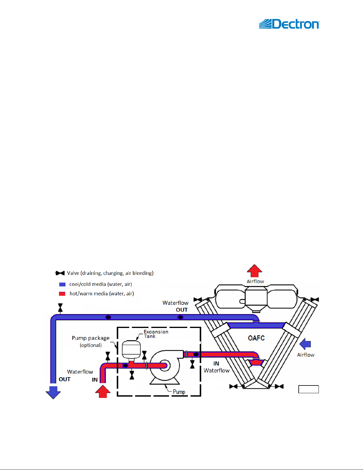
Dry cooler rejects the heat, absorbed by the cooling media (water etc.) from the external system(s) that dry cooler
serves, to the outdoor air.
Operation and Media Flow
Dry cooler operation is quite simple:
•Upon the command (when heat rejection is needed) dry cooler engages its fan(s) to establish the airflow
across the coil(s).
oDepending on the type of fans (modulating EC-type or two-speed), control type and command
received, cooler total airflow is adjusted by varying fan(s) speed and/or number of operating fans.
•Cooling media flow must be established also –either by separately controlled pump (part of the external
system) or by the built-in pump package pump. In latter case, pump would engage with the fan(s) and will stay
engaged while the command exists (while at least one fan is running).
•Until call for heat rejection is satisfied and command to dry cooler is removed, fan(s) and pump will run; once
command removed, all fans and the pump will stop.
Pic. C.4 below shows schematic layout of dry cooler operation and media (air and water/glycol) flow.
For more details on dry cooler piping connection refer to Installation Manual, submittal documentation etc. as well
as local Codes and proper field practices.
Pic. C.4

Dectron Dry Cooler OMM 8September 2020
Control
There may be some different types of controls used with NG series dry coolers.
Fan type:
•Modulating (EC-type) fans are capable of varying their speed (from 0 to 100%) based on 0-10VDC signal. These
fans are standard on NG series dry coolers built since 2020 and may be found on some built prior.
•Two-speed fans are capable of running in two alternative speed (low or high); normally done by switching
between “star” and “delta” motor wiring (fans are pre-wired from the factory to switch from one to another,
based on respective contactor –low or high speed –being engaged). These fans typically are used on legacy
mid- to large size multi-fans dry coolers.
oStaging. Standard (and the most simplistic) staging uses just two stages –low speed and high speed –
where all fans are running together (in low or high speed, as commanded).
Control Type (all control types referenced below are applicable to all fans type described above):
•Externally controlled Dry cooler. Fan(s) speed signal (modulating or stage switch-over) is provided from
external system (usually –the one that dry cooler serves, to satisfy said system operational requirement). This
is typical for dry cooler serving single systems. Typical signal type for this control type are modulating (0-
10VDC) or two-speed switch-over (however, other arrangements are available). It may control the fan
according to head pressure or another control method chosen by installer.
•Self-controlled (“stand-alone”) Dry cooler. Fan(s) speed signal (modulating or stage switch-over) is based on
built-in control device. Most commonly used one is an aquastate, monitoring temperature of the cooling
media (water/glycol mixture), leaving the dry cooler.
oTypically, aquastat is pre-set to maintain entering cooling media temperature at certain level: the
sensor issues the signal to start the fan(s) and increase their speed as temperature increases (and,
respectively, reduce fans’ speed when temperature reduces). Typically, this signal is 0-10vdc –it
could be accepted by EC-type fans directly or translated into staging signal with additional device (this
allows to set more than two stages to finetune dry cooler operation).
Dry cooler is normally provided with the wiring diagram, depicting its specific control schematic –refer to it as
needed.

September 2020 9Dectron Dry Cooler OMM
Layout and Components
General layout of the various NG-series dry coolers is shown on Pic.D.1 below. While layout and main components
are similar for all applicable dry coolers, there are some deviations (number of fans and coils, composition, etc.).
Refer to Views and Options (Basic Information chapter) for additional information:
Dry cooler Main Components
36
35
33
37
31
33
31

Dectron Dry Cooler OMM 10 September 2020
32

September 2020 11 Dectron Dry Cooler OMM
Fig. 1, 2 and 4 show NG-V type dry coolers (two, six and single-fan models, respectively), while Fig. 3
shows NG-Z type dry cooler.
Examples show all/most available options (like pump package etc.); some of shown options may not be
present on your dry cooler –refer to submittal documentation as needed.
•Cooling airside coil(s) (31) (where heat from glycol mixture is rejected to the ambient air) is mounted onto
metal frame, upstream (before) the fan(s) (32), that pulls the air through the coils to absorb the heat.
oDepending on the equipment type and required capacity, dry cooler may have one or multiple coils
and fans –refer to Views and Options (Basic Information chapter).
•Dry cooler piping connections (33) are identified in respect to cooling media flow direction (hot/warm media
entering the dry cooler –IN, cool media leaving the dry cooler –OUT);
oIn some cases, dry cooler piping connection(s) may be located within pump package box (37), if dry
cooler is provided with one.
oPiping connection location may vary –refer to particular cooler labels, stickers, submittal and other
documentation.
oDry cooler manifold/connection, normally, is not equipped with isolating valves, filters etc. (this also
applies to pump package, if dry cooler is equipped with such option; see pump package layout
below).
•For NG-Z type (Fig. 3) ONLY! Said dry cooler ships with set of legs (34) to provide sufficient space between
horizontal mounting surface and airflow intake. On-site assembly is required for these legs. For more details
on the installation refer to the Installation Manual.
•Electric power is normally to be brought to disconnect (35) (if cooler is equipped with such), which feeds it to
the electrical box (36), that contains dry cooler power and control apparatuses.
oDepending on dry cooler specifics, location of electrical box may slightly differ; in some cases,
electrical box may be incorporated into pump package or located on the opposite side of the dry
cooler.
Pic. D.1
32
36
35
33
34
37
31
31
Dectron Dry Cooler OMM 12 September 2020
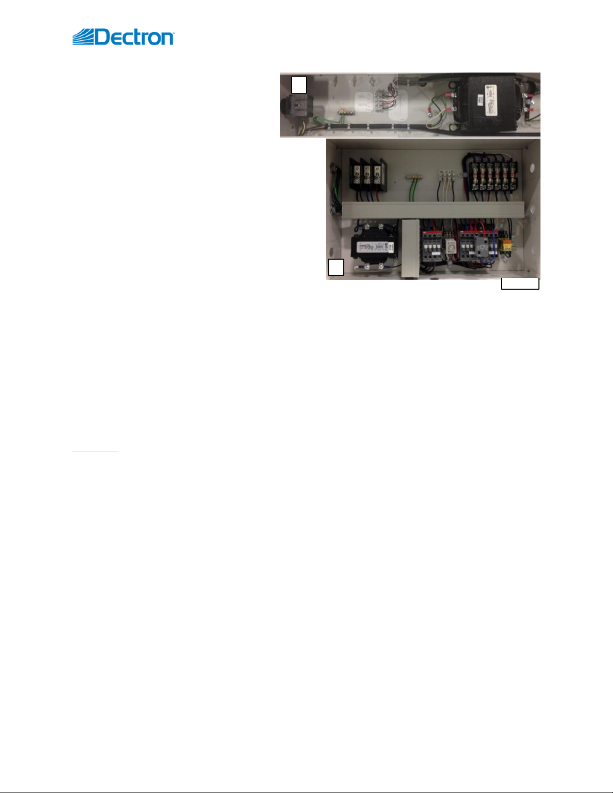
Electrical Box –Power and Control
Dry cooler power and control wiring and
apparatuses (transformer, contactor(s), fuses,
wiring terminals etc., as applicable) are located
in the electrical box, shown on Pic. D.2: typical box of dry
cooler type NG-Z (a) and type NG-V (b):
•In some cases dry cooler electrical box could be
incorporated within pump package.
•NG-V type dry cooler with multiple fans would have
multiple boxes (typically –one box per one pair of
fans).
oMultiple electrical boxes on one dry cooler are
normally connected to each other at the
factory, so external power and control wiring
has to be brought only to one (main) electrical box.
•Depending on the specifics of the dry cooler (size, type of fans, control method etc.), electrical box layout and
components may vary –refer to your dry cooler submittal, wiring diagram and other documentation.
Pump Package
If equipped with such option, dry cooler would have a pump package box. Pic.D.3 below shows general layout of
pump packages, used for NG-V model dry coolers. Note, that the package could be mounted onto the dry cooler
directly (standard) or provided separately.
Dry coolers Pump Package
Dry coolers, if equipped with such option, would have a pump package box. Pic.D.6 below shows general layout of
pump packages, used for NG series: NG-Z (a) and NG-V (b) type, respectively. Note that the package used with NG-
V coolers is normally mounted onto the cooler directly, however, it also could be provided separately.
•Pump (38) establishes glycol mixture circulation through the dry cooler and dehumidifier;
•Expansion tank (39) compensates for temperature-based glycol/cooling fluid volume fluctuation;
•The pump package electrical sub-panel (40) contains the pump package electrical power and control
apparatuses.
oIn some cases, pump package electrical sub-panel may contain power and control apparatuses for the
entire dry cooler (fan(s) and pump package).
•The pump package manifolds are usually equipped with pressure gauges, automatic air venting and manual
draining/charging valves.
Pic. D.2
b
a

September 2020 13 Dectron Dry Cooler OMM
Basic Maintenance
Although dry cooler is built for minimal service downtime, periodic preventative maintenance is required to
ensure maximum reliability, safety, and operating efficiency.
Maintenance and Safety
Only qualified/properly trained personnel should attempt to perform respective maintenance tasks.
•Live Electric Power! When necessary, have a licensed electrician or other qualified professional to perform the
required task.
•Turn the power off. Before performing any maintenance, disconnect all electrical power, including remote
disconnect, and discharge all energy storing devices (capacitors, VFDs, etc.) before servicing. Follow proper
lockout procedures to ensure that power cannot be accidentally restored. Failure to follow provided safety
warnings and labels could result in serious injury or death.
40
38
39
38
40
39
Pic. D.3
a
b
WARNING! To ensure equipment longevity and proper and efficient operation, it must be maintained
properly. It is recommended to create a facility-specific Routine Maintenance Program.
Failure to perform necessary maintenance task(s) properly and regularly could result in personal injury,
equipment damage or malfunction and will void the equipment warranty.
Dectron Dry Cooler OMM 14 September 2020
•Be properly trained and equipped. Some maintenance tasks may involve usage of power tools, chemicals, etc.
Refer to such tools and materials data (manuals, MSDS, etc.). Personnel performing such maintenance tasks
should be:
oProperly trained to handle such tools and materials safely
oEquipped with proper personal protective equipment
•Be aware of potential hazards. The equipment contains moving mechanical parts, components with water-
glycol mixture under the pressure (refer to the equipment main label for the details as eeded) and some
hot/warm surfaces. Before performing any equipment maintenance work, make sure that all moving parts are
stopped, and it is safe to perform required task.
Maintenance Key Points
Dry cooler is rather low-maintenance equipment, yet there are some basic/key maintenance considerations:
•Ensure that the equipment is accessible (minimum clearances are maintained): approaches are not
restricted/limited (with materials, other equipment, manifolds, snow etc.).
•Maintain clean airside coils surfaces: make sure to clean coils from cobweb, dust, leaves etc. regularly.
Routine Maintenance Program
Creating facility-specific routine maintenance program and following it is vital to equipment longevity and efficient
operation.
Detailed maintenance recommendations for specific components, as/if needed, could be sourced from respective
component manufacturer or other documentation.
The suggested general maintenance tasks and their frequency/intervals, listed below, can be used to create
mentioned maintenance program (be aware that list below is a suggestion only - frequency and tasks may vary per
installation, based on various factors like ambient environment cleanliness, type of equipment etc.):
Monthly –Quartely
Observe equipment general operation (for unusual vibration, noise etc.)
Verify control settings (applicable to “self-controlled” equipment)
Inspect the airside coils for dirt, cobweb build-up, etc.; clean as needed
Semi-Annually –
Annually
Check electrical connections (both, power and control), tighten as needed
Check the frame and fasteners for being structurally sound (loose fasteners,
corroded/deteriorating components etc.)
Check glycol/water mixture ratio/percentage, adjust as needed.
Specific Components Maintenance and Special Tasks.
Airside Coil(s) Cleaning.
•Warning: Hazardous chemicals! Cleaning agents can be highly acidic or alkaline. Handle all chemicals carefully
and use appropriate personal protective equipment (PPE). Refer to the cleaning agent manufacturer's Materials
Safety Data Sheet (MSDS) for safety and handling information. Failure to follow all safety instructions could
result in serious injury or death.
To clean the coil:
•Disconnect all electrical power to the equipment
•Use a soft brush to remove loose debris from the coil
•Mix a high-quality coil cleaning detergent with water according to the manufacturer's instructions
September 2020 15 Dectron Dry Cooler OMM
•Clean coil according to suggested instructions
•Thoroughly rinse both sides of the coil and the drain pan with, clean water
•Straighten any coil fins that have been bent during the cleaning process
•Replace all panels and parts and restore electrical power to the equipment
Dry Cooler Service.
Normally dry coolers are filled with glycol mixture to prevent the system and the dry cooler from freezing and
potentially rupturing pipes when exposed to temperatures below freezing point.
When dry cooler is used with media that, when exposed to low temperatures, could freeze (pure water or very
low-percentage glycol mixture), one way to protect the equipment is to drain it (also known as “winterization” of
the equipment).
Though dry cooler itself is normally equipped with means to be drained properly/fully, it is recommended to have
same means in place for entire system/equipment dry cooler serves:
•Have each local high point of the system equipped with means to bleed the air (air bleeding valve etc.)
•Have each local low point of the system equipped with means to drain the fluid.
Warranty
General Policy
All Dectron service and warranty work is managed exclusively by Dehumidified Air Services (DASV). All warranties
apply to the original equipment owner and are not transferable. All warranty inquiries should be made to
Dehumidified Air Services.
Dehumidified Air Services:
Phone: 1-833-327-7665 Email: Warranty@DehumidifiedAirServices.com
Dectron warrants as set forth and for the time periods shown below that it will provide through either a DASV
Service Technician or an authorized service organization specified and approved by DASV, a new or rebuilt part to
replace a factory installed part which has failed because of defect in workmanship or material.
NOTE: EVERY REQUEST RELATED TO WARRANTY OF ANY NATURE AS DESCRIBED BELOW MUST BE OFFICIALLY
AUTHORIZED AND DOCUMENTED IN ADVANCE BY DASV TO QUALIFY FOR WARRANTY COVERAGE.
Warranty Void Unless Registered
All Warranties are void unless the start-up of the equipment is approved by a DASV service technician. Upon
completion of the start-up, a “Warranty Registration Certificate” will be issued, along with the Start-Up Report,
which activates the Warranty Period of the equipment. The Warranty Period will commence either upon
completion of start-up registration of the equipment or 6 months from factory ship date, whichever comes first.
CAUTION. Draining and re-filling the dry cooler must be performed by trained personnel, according to proper
field practice and system layout. Improper draining or re-filling the system could lead to equipment damage,
malfunction, premature wear and tear and may void equipment warranty. Ensuring that the dry cooler and associated
system(s) equipped with proper means of draining, creating draining and re-filling procedures as well as determining
whether draining is warranted to protect the equipment is outside of manufacturer’s scope and is a sole responsibility
of installing contractor and local maintenance team.

Dectron Dry Cooler OMM 16 September 2020
Initial 90‐Day Comprehensive Warranty
During the first 90 days from initial start-up, all parts and repairs related to factory defects or replacement parts
are covered by Dectron manufacturer warranty. All parts and labor requirements will either be handled by DASV
technicians directly or managed and approved in advance by DASV through DASV authorized technicians.
Internet Connected, Conditional One Year Repair Warranty
If and only if the equipment is connected to the internet from the date of warranty activation, a Repair Warranty
will be provided for an additional 9 months subsequent to the initial 90-Day Comprehensive Warranty for a total of
12 months of parts and labor warranty coverage. The unit must be connected and communicating to Dectron
Vision 2.0 for the entire term from start-up in order to qualify.
If qualified, Dectron will provide or pay for the required part and direct labor only, related to the part replacement.
Only the labor required to replace the defective part is under warranty for this 9-month extension. Travel time,
diagnostic time, per diems, truck charges, shipping charges etc. are not covered under this Conditional Repair
Warranty.
Two-Year Parts Warranty
If any factory installed part supplied by Dectron fails because of a defect in workmanship or material prior to the
completion of the 24th month from date of completion of the warranty activation, Dectron will provide a new or
rebuilt part F.O.B. factory. No labor reimbursement will be made for expenses incurred in replacing the part except
as set in the Initial 90‐day Comprehensive or Internet Connected, Conditional One-Year Repair Warranty.
Dectron reserves the right to have the defective part returned to the factory in order to determine the warranty
applicability. Parts shipping and handling costs (to and from the factory) are not covered outside of the Initial 90‐
day Warranty.

September 2020 17 Dectron Dry Cooler OMM
Replacement Part Warranty
If a replacement part provided by Dectron under this warranty fails due to a material defect prior to the end of the
Two-Year Parts Warranty (or the end of the extended warranty period if applicable), whichever comes first,
Dectron will provide a new or rebuilt part F.O.B. factory.
Applicability
This warranty is applicable only to products that are purchased and installed in the United States and Canada. This
warranty is NOT applicable to:
1. Products that have become defective or damaged as a result of non-DASV or unauthorized service work,
poor maintenance, faulty electrical supply, act of God, or any other circumstances outside of the specified
care, maintenance or operation of the equipment including:
•Components that have been relocated from their original placement during manufacturing.
•Any portion of the system not supplied by Dectron.
•Components on which the model and/or serial number plates have been removed or defaced.
•Components which have become defective or damaged as a result of unauthorized opening of the
refrigeration circuit, improper wiring, electrical supply characteristics, poor maintenance, accidents,
transportation, misuse, abuse, fire, flood, alteration and/or misapplication of the product.
•Products not installed, operated and maintained as per the Dectron Operating and Maintenance
Manual.
•Products operating in mechanical rooms that house chemicals (i.e. chlorine, bromine, water
treatment chemicals).
•Products on which payment is in default.
2. Parts that wear out due to normal usage, such as air filters, fuses and sensors are not covered by this
warranty.
NOTE: Refrigerant lost during the Initial 90‐day Comprehensive or Internet Connected, Conditional One-Year
Repair Warranty will be reimbursed in accordance to the current market price of refrigerant at the time of
repair and upon discretion of DASV’s Customer Support team. Dectron will not be responsible for refrigerant
lost from the system due to improperly installed contractor piping to the remote outdoor air-cooled
condenser.
Limitations
1. DASV is a Manufacturer Service organization, not a first-response or urgent response local service
company. As such, we highly recommend that equipment owners have a relationship with their own
qualified first response service organization or one recommended by DASV.
DASV hours of operation are from 8:00 AM to 6:00 PM Eastern, Monday through Friday unless otherwise
agreed to under a separate agreement.
Parts replacement can be subject to availability. We highly recommend for mission-critical applications
that owners purchase and maintain a local stock of critical components in case immediate replacement be
required. If for any reason one of those components is replaced under applicable warranty conditions,
Dectron will reimburse the original cost of any component used under terms of Warranty.
NOTE: Dectron expressly disclaims any liability for parts replacement delays due to parts unavailability or
shipping delays.
2. This warranty is given in lieu of all other warranties. Anything in the warranty notwithstanding, any
implied warranties of fitness for particular purpose and merchantability shall be limited to the duration of
Dectron Dry Cooler OMM 18 September 2020
the warranties described above. Dectron expressly disclaims and excludes any liability for consequential
or incidental damage for breach of any express or implied warranty.
Where a jurisdiction does not allow limitations or exclusions in a warranty, the foregoing limitations and
exclusions shall not apply to the extent of the legislation, however, in such case the balance of the above
warranty shall remain in full force and effect.
This warranty gives specific legal rights. Other rights may vary according to local legislation.
Force Majeure
Dectron will not be liable for delay or failure to provide warranty service due to government restrictions or
restraints, war, strikes, material shortages, acts of God or other causes beyond Dectron control.
Table of contents


