PoolPak PCP Series User manual

PoolPak.com
OPERATION AND MAINTENANCE MANUAL
DEHUMIDIFIERS
PCP SERIES
Indoor

Table of Content
General Information....................................................................................................................... 2
Operating Safety (Warnings, Cautions, and Notes)...................................................................................2
Reference and Additional Information......................................................................................................3
Basic Information.......................................................................................................................................4
Dehumidifier External Systems Connection –S Cab .................................................................................5
Dehumidifier External Systems Connection –RH and RV cabs.................................................................8
Dehumidifier External Systems Connection ............................................................................................12
Layout and Components .............................................................................................................. 17
Dehumidifier Main Components –S cab.................................................................................................17
Dehumidifier Main Components –RV and RH Cabs................................................................................19
Control System.........................................................................................................................................24
Sequence of Operation ................................................................................................................ 30
Ventilation. ..............................................................................................................................................30
Space Heating ..........................................................................................................................................30
Air Conditioning, Dehumidification and Pool Heating.............................................................................30
Compressor(s)..........................................................................................................................................30
Interface and Communication ..................................................................................................... 32
Touch Display Operator Panel .................................................................................................................32
Remote Communication..........................................................................................................................34
Basic Maintenance ....................................................................................................................... 35
Maintenance and Safety..........................................................................................................................35
Maintenance Key Points..........................................................................................................................35
Specific Components Maintenance.........................................................................................................37
Special Maintenance Tasks. Fluid Cooler Winterization. ........................................................................38
Pools –Equipment Warranty....................................................................................................... 39

PoolPak PCP Series –Indoor OMM 2September 2020
General Information
This manual provides basic information about the applicable dehumidifier and its operation.
Important information regarding installation, maintenance, and start up as well as additional and auxiliary systems
and devices (outdoor condenser, communication interfaces, etc.) is normally provided with the dehumidifier and
can also be obtained at factory (see Contact Us below).
Operating Safety (Warnings, Cautions, and Notes)
FOR YOUR SAFETY: READ BEFORE PERFORMING ANY OPERATIONS, MAINTENANCE OR SERVICE TASKS!
Only qualified technicians should install, operate, maintain or service mechanical equipment
including current dehumidification system.
Make sure to read this manual before performing any tasks to familiarize yourself with the
equipment as well as with any potential hazards. Always exercise caution!
Beware of electrical power and high electrical voltage!
•Follow proper safety procedures –lockout, tagout, and other respective procedures
•Failure to follow safety procedures can result in serious injury or death
Beware of moving parts and hot surfaces!
•Make sure to stop all moving parts (fans, blowers, etc.) before accessing the equipment’s
internal space
•Be aware of hot surfaces (hot refrigeration, space heating pipes, coils, heaters, etc.)
Beware of high pressures and chemicals!
•Dehumidifiers, equipped with compressors, contain refrigerant under high pressure; oil is
also contained in the compressor and refrigeration circuit(s)
•Some dehumidifiers may also contain other liquids such as glycol mixtures and pool water
The following warnings, cautions, and notes appear throughout this manual and referenced documentation
whenever special care must be taken to avoid potential hazards that could result in equipment malfunction or
damage, personal injury, or death.
WARNING
Indicates a potentially hazardous
situation which could result in
serious injury or death if handled
improperly.
CAUTION
Indicates a potentially hazardous
situation which could result in
moderate injury or equipment
damage if handled improperly.
Note
Indicates a situation that could
result in equipment damage or
improper/ineffective operation if
handled improperly.

September 2020 3PoolPak PCP Series –Indoor OMM
Reference and Additional Information
For safe, efficient and problem-free operation, it is critical to handle the dehumidifier (as well as related systems
and components) properly at each step - from receiving and storage to installation and start up. Relevant
information can be found in the respective documents (like Installation Manual) provided with the dehumidifier.
This manual and other related documents could be obtained from the manufacturer (see Contact Us below).
Contact Us
PoolPak
3491 Industrial Drive
York, PA 17403
USA
PoolPak.com
1-833-DAS-POOL (327-7665)
Schedule / Modify a Start-up:
Startups@DehumidifiedAirServices.com
Inquire about Warranty:
Warranty@DehumidifiedAirServices.com
Order Parts:
Parts@DehumidifiedAirServices.com
All Other Product Support:
Support@DehumidifiedAirServices.com
Attention: Installation and Service Contractors
WARNING! Any work (installation, start up, service, maintenance, repair, etc.) on any mechanical
equipment (dehumidifier, outdoor condenser, fluid cooler, etc.) must be performed in accordance with
respective manufacturer’s recommendations as well as submittal documentation, local Codes and Regulations,
and appropriate field practices. Failure to do so could result in personal injury, equipment damage or
malfunction, and will void equipment warranty. Only qualified and properly trained individuals should perform
tasks on this equipment.
Attention: Maintenance Team
CAUTION. To ensure equipment longevity and proper and efficient operation, the dehumidifier and its
auxiliary systems and devices (outdoor condenser, fluid cooler, etc.) should be maintained properly and regularly.
Failure to do so could negatively affect premise comfort levels and people’s health. It could also lead to
equipment damage, malfunction, premature tear and ware and may void equipment warranty.

PoolPak PCP Series –Indoor OMM 4September 2020
Basic Information
Dehumidifier View and Options –S Cab
Standard PCP800 and PCP1200 dehumidifier’s general views and options * are shown on Pic.C.1.
Dehumidifier Options:
•Indoor, single-compressor dehumidifiers 2 and 3 tons’capacity (apprx.) - models PCP800 and PCP1200 *.
oTwo-compressor dehumidifier option (see Dehumidifier Optional Arrangement below for details):
4 and 6 ton cooling capacity (appx.) - models PCP808 and PCP1212.
•Airflow and ductwork connection options* (Return Air, Supply Air, Outdoor Air) - as shown on Pic. C.1.
•Optional Pool Water Heating **.
•Optional Space Heating - hot water coil, electric or gas heater ***.
•Air Conditioning (AC)* –external water cooling, outdoor condenser or fluid cooler.
Options:
•Return Air (RA) ductwork connection -
horizontal.
•Supply Air (SA) ductwork connection
options –top, bottom, horizontal*.
•Outdoor Air (OA) intake - horizontal*.
Piping Connections
①
Condensate Drain
②
AC –Air-Cooled (refrigeration)
③
AC –Water-Cooled (water/glycol)
④
Pool Heating Water
⑤
Space Heating Hot Water
Pic. C.1

September 2020 5PoolPak PCP Series –Indoor OMM
* All available options (tonnage, ductwork connections, AC options etc.) are shown. Refer to the submittal
and other relevant documentation for your equipment options, dimensions etc.
** The pool water heating option relies on compressor-created excess heat and is used as an additional
heating source. It does not eliminate the need for a main pool water heater.
*** For specific details on space heating (hot water, gas, electric) option, refer to the submittal and other
documentation:
•Gas-fired duct heater can be provided for field installation (to be fitted in the supply air ductwork).
•Electric heater or hot water coil, depending on capacity, model, size, etc., can be installed externally (mounted on the
top of SA opening or fitted in the supply air ductwork) or internally. Refer to your dehumidifier’s submittal
documentation.
Dehumidifier External Systems Connection –S Cab
Pic. C.1 shows provisions for external systems connections, including ductwork, electric power and control wires
and various piping connections.
•Except for the condensate, all other piping systems are optional and may not be present in each dehumidifier.
•Air Conditioning (AC) Connection. Normally, the dehumidifier has only one AC option –air-cooled (requiring
connection to the outdoor air condenser) or water-cooled (requiring connection to the fluid cooler or other
external water-cooled system such as geothermal, cooling tower, etc.). Therefore, only one of these options
present with the actual dehumidifier.
•Gas line. If the dehumidifier is equipped with a gas heater for space heating purposes, the gas line connection
is to be brought to the gas heater directly.
Attention! Equipment Clearances and Dimensions!
CAUTION! For equipment proper operation, maintenance and service, respective clearances should be
maintained. Generally, 30” clearances to the equipment must be kept for the maintenance and service purposes.
For the specific required clearances information, as well as dehumidifier overall dimensions, distances to pipe
connections, duct connections etc., refer to the submittal documentation.
NOTE. Dehumidifier MUST be equipped with a P-trap at the condensate connection for proper operation! If
dehumidifier is requested/provided from the factory without P-trap, one MUST be installed on site prior to
dehumidifier being commissioned. Refer to the dehumidifier stickers and Installation Manual for details.
CAUTION! Current manual shows general/default connections’ location. For details regarding specific
dehumidifier’s connections (actual location, piping sizes and position dimensions, circuit type and flow direction
etc.), refer to the dehumidifier’s submittal documentation as well as dehumidifier’s labels and stickers.
WARNING! Gas Line. The gas line must be installed in accordance with respective device documentation
and local codes and regulations.

PoolPak PCP Series –Indoor OMM 6September 2020
Dehumidifier View and Options –RV and RH Cabs
Standard PCP1400 –PCP2600 dehumidifiers come in vertical (Pic.C.1-A) or horizontal (Pic.C.1-B) composition:
Vertical Composition
•Return Air (RA) ductwork connection -
horizontal.
•Supply Air (SA) ductwork connection
options –top, horizontal (left or right).
•Outdoor Air (OA) intake - top
Piping Connections
①
Condensate Drain
②
AC –Air-Cooled (refrigeration)
③
AC –Water-Cooled (water/glycol)
④
Pool Heating Water
⑤
Space Heating Hot Water
Pic. C.1-A

September 2020 7PoolPak PCP Series –Indoor OMM
Horizontal Composition
•Return Air (RA) ductwork connection -
horizontal.
•Supply Air (SA) ductwork connection
options –top, bottom, horizontal (straight).
•Outdoor Air (OA) intake ductwork
connection options –top, horizontal.
Piping Connections
①
Condensate Drain
②
AC –Air-Cooled (refrigeration)
③
AC –Water-Cooled (water/glycol)
④
Pool Heating Water
⑤
Space Heating Hot Water
Pic. C.1-B

PoolPak PCP Series –Indoor OMM 8September 2020
Dehumidifier Options (applicable to both, vertical and horizontal, configurations):
•Indoor, single-compressor dehumidifiers, 4 to 7 ton cooling capacity (apprx.) - models PCP1400 to PCP2600 *.
oTwo-compressor dehumidifier option (see Dehumidifier Optional Arrangement below for details):
8 to 14 ton cooling capacity (appx.) - models PCP1414 to PCP2626
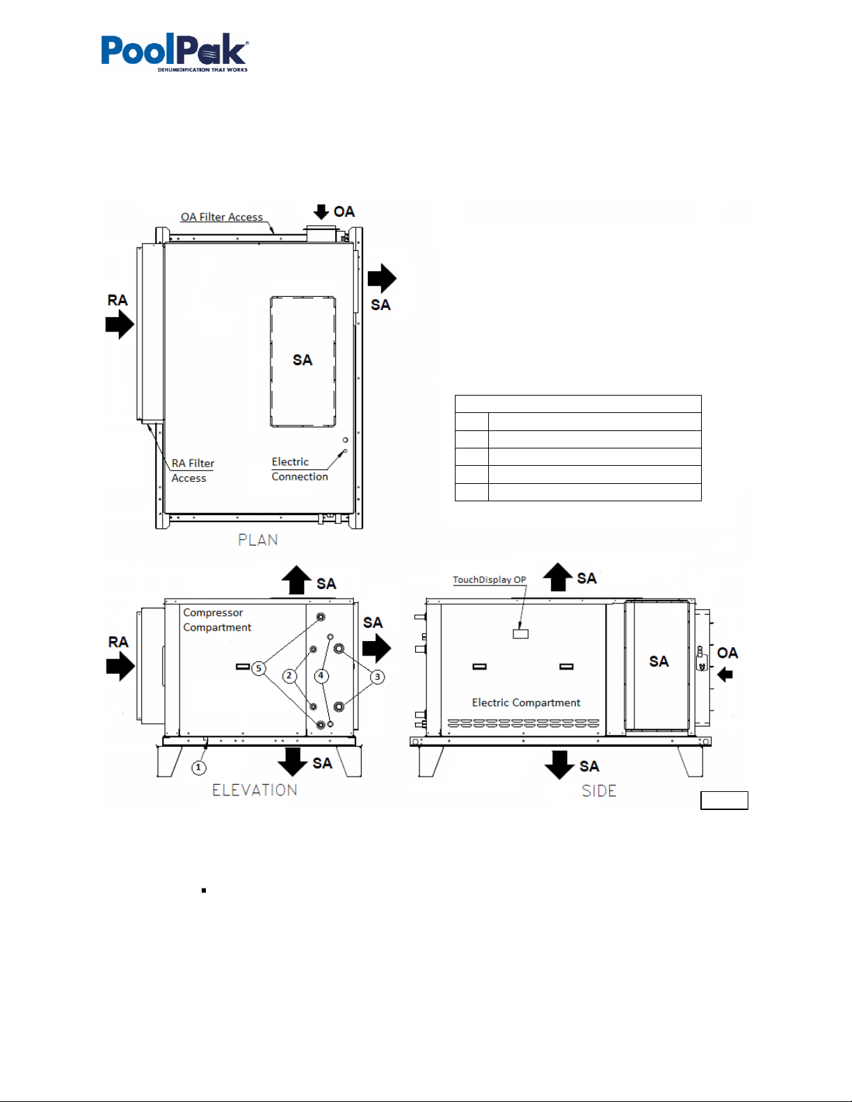
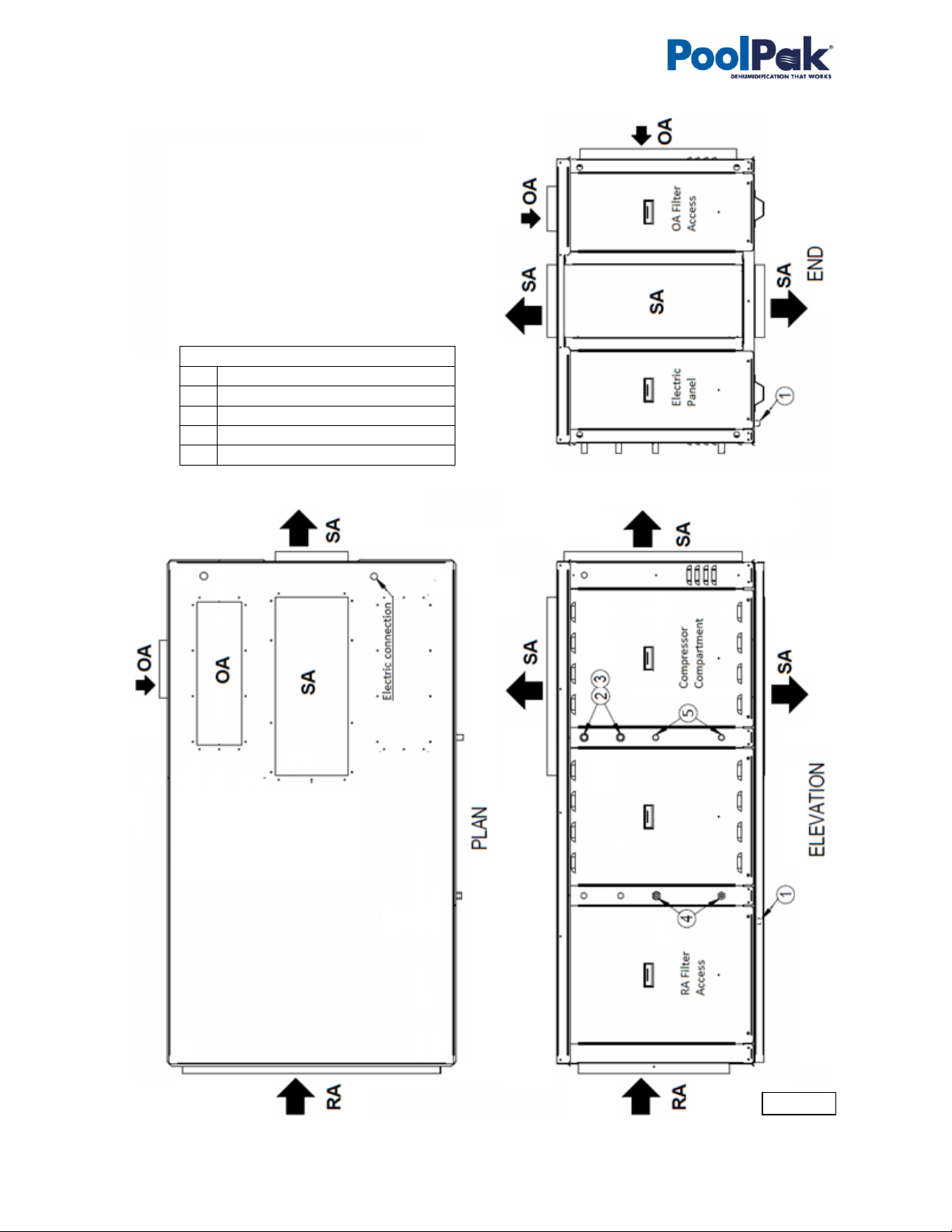
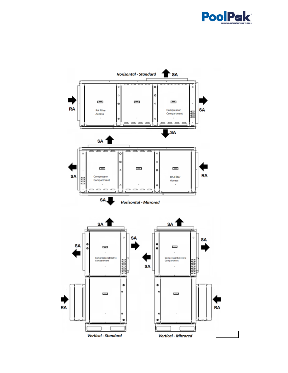
•Airflow and ductwork connection options* (Return, Supply and Outdoor Air) - see Pic. C.1-A and C.1 –B.
•Optional Pool Water Heating **.
•Optional Space Heating - hot water coil, electric or gas heater ***.
•Air Conditioning (AC)* –external water cooling, outdoor condenser or fluid cooler.
* All available options (tonnage, ductwork connections, AC options etc.) are shown. Refer to the submittal
and other relevant documentation for your equipment options, dimensions etc.
** The pool water heating option relies on compressor-created excess heat and is used as an additional
heating source. It does not eliminate the need for a main pool water heater.
*** For specific details on space heating (hot water, gas, electric) option, refer to the submittal and other
documentation:
•Gas-fired duct heater can be provided for field installation (to be fitted in the supply air ductwork).
•Electric heater, depending on various factors (capacity, model, size, etc.), can be installed externally (mounted on the
top of SA opening) or internally. Refer to your dehumidifier’s submittal documentation.
Dehumidifier External Systems Connection –RH and RV cabs
Pic. C.1 –A and B show provisions for external systems connections, including ductwork, electric power and
control wires and various piping connections.
•Except for the condensate, all other piping systems are optional and may not be present in each dehumidifier.
•Air Conditioning (AC) Connection. Normally, the dehumidifier has only one AC option –air-cooled (requiring
connection to the outdoor air condenser) or water-cooled (requiring connection to the fluid cooler or other
external water-cooled system such as geothermal, cooling tower, etc.). Therefore, only one of these options
present with the actual dehumidifier.
•Gas line. If the dehumidifier is equipped with a gas heater for space heating purposes, the gas line connection
is to be brought to the gas heater directly.
Attention! Equipment Clearances and Dimensions!
CAUTION! For equipment proper operation, maintenance and service, respective clearances should be
maintained. Generally, 30” clearances to the equipment must be kept for the maintenance and service purposes.
For the specific required clearances information, as well as dehumidifier overall dimensions, distances to pipe
connections, duct connections etc., refer to the submittal documentation.
NOTE. Dehumidifier MUST be equipped with a P-trap at the condensate connection for proper operation! If
dehumidifier is requested/provided from the factory without P-trap, one MUST be installed on site prior to
dehumidifier being commissioned. Refer to the dehumidifier stickers and Installation Manual for details.
CAUTION! Current manual shows general/default connections’ location. For details regarding specific
dehumidifier’s connections (actual location, piping sizes and position dimensions, circuit type and flow direction
etc.), refer to the dehumidifier’s submittal documentation as well as dehumidifier’s labels and stickers.
WARNING! Gas Line. The gas line must be installed in accordance with respective device documentation
and local codes and regulations.

September 2020 9PoolPak PCP Series –Indoor OMM
Dehumidifier Optional Arrangement –RH and RV Cabs
Mirrored Arrangement
Both, horizontal and vertical, dehumidifier could have standard and mirrored cabinet arrangement (see Pic.C.2).
Note, that all options and details, described above, apply to both, standard and mirrored arrangement.
Pic. C.2

PoolPak PCP Series –Indoor OMM 10 September 2020
Dehumidifier View and Options –BH and BV cabs
Standard PCP3000 –PCP6000 dehumidifiers come in horizontal (Pic.C.1-A) or vertical (Pic.C.1-B) composition:
Pic. C.1-A
Horizontal Composition
•Return Air (RA) ductwork connection -
horizontal.
•Supply Air (SA) ductwork connection
options –top, bottom, horizontal side
(left or right).
•Outdoor Air (OA) intake ductwork
connection options –top, horizontal side
(left or right).
Piping Connections
①
Condensate Drain
②
AC –Air-Cooled (refrigeration)
③
AC –Water-Cooled (water/glycol)
④
Pool Heating Water
⑤
Space Heating Hot Water
Electrical connection

September 2020 11 PoolPak PCP Series –Indoor OMM
Dehumidifier Options (applicable to both, vertical and horizontal, configurations):
•Indoor, single-compressor dehumidifiers, 8 to 16 tons’ capacity (apprx.) - models PCP3000 to PCP5000 *.
oTwo-compressor dehumidifier option (16 to 32 tons’ capacity (appx.) - models PCP3030 to PCP5050
as well as models PCP5500 and PCP6000) - see Dehumidifier Optional Arrangement below.
•Airflow and ductwork connection options (Return Air (RA), Supply Air (SA) Outdoor Air (OA)) * - as shown on
Pic. C.1-A and C.1 –B.
•Optional Pool Water Heating **.
•Optional Space Heating - hot water coil, electric or gas heater ***.
•Air Conditioning (AC)* –external water cooling, outdoor condenser or fluid cooler.
Vertical Composition
•Return Air (RA) ductwork connection -
horizontal.
•Supply Air (SA) ductwork connection
options –top, horizontal side (left or
right).
•Outdoor Air (OA) intake –top, horizontal
side (left or right).
Piping Connections
①
Condensate Drain
②
AC –Air-Cooled (refrigeration)
③
AC –Water-Cooled (water/glycol)
④
Pool Heating Water
⑤
Space Heating Hot Water
Electrical connection
Pic. C.1-B

PoolPak PCP Series –Indoor OMM 12 September 2020
* All available options (tonnage, ductwork connections, AC options etc.) are shown. Refer to the submittal
and other relevant documentation for your dehumidifier’s options.
** The pool water heating option relies on compressor-created excess heat and is used as an additional
heating source. It does not eliminate the need for a main pool water heater.
*** For specific details on space heating (hot water, gas, electric) option, refer to the submittal and other
documentation:
•Gas-fired duct heater can be provided for field installation (to be fitted in the supply air ductwork).
•Electric heater or hot water coil, depending on capacity, model, size, etc., can be installed externally (mounted on the
top of SA opening or fitted in the supply air ductwork) or internally. Refer to your dehumidifier’s submittal
documentation.
Dehumidifier External Systems Connection
Pic. C.1 –A and B show provisions for external systems connections, including ductwork, electric power and
control wires and various piping connections.
•Except for the condensate, all other piping systems are optional and may not be present in each dehumidifier.
•Air Conditioning (AC) Connection. Normally, the dehumidifier has only one AC option –air-cooled (requiring
connection to the outdoor air condenser) or water-cooled (requiring connection to the fluid cooler or other
external water-cooled system such as geothermal, cooling tower, etc.). Therefore, only one of these options
present with the actual dehumidifier.
•Gas line. If the dehumidifier is equipped with a gas heater for space heating purposes, the gas line connection
is to be brought to the gas heater directly.
Attention! Equipment Clearances and Dimensions!
CAUTION! For equipment proper operation, maintenance and service, respective clearances should be
maintained. Generally, 30” clearances to the equipment must be kept for the maintenance and service purposes.
For the specific required clearances information, as well as dehumidifier overall dimensions, distances to pipe
connections, duct connections etc., refer to the submittal documentation.
NOTE. Dehumidifier MUST be equipped with a P-trap at the condensate connection for proper operation! If
dehumidifier is requested/provided from the factory without P-trap, one MUST be installed on site prior to
dehumidifier being commissioned. Refer to the dehumidifier stickers and Installation Manual for details.
CAUTION! Current manual shows general/default connections’ location. For details regarding specific
dehumidifier’s connections (actual location, piping sizes and position dimensions, circuit type and flow direction
etc.), refer to the dehumidifier’s submittal documentation as well as dehumidifier’s labels and stickers.
WARNING! Gas Line. The gas line must be installed in accordance with respective device documentation
and local codes and regulations.

September 2020 13 PoolPak PCP Series –Indoor OMM
Dehumidifier Optional Arrangement.
Two-Compressor Arrangement
Standard PCP series dehumidifier has one compressor,
however two-compressor arrangement is available also. Note,
that all options and details, provided above, apply to both,
standard and two-compressor arrangement:
•Single Deck dehumidifier has same dimensions,
features and options as standard single-compressor
one, except for two compressor/refrigeration circuits
instead of one.
•“Double-Decker” dehumidifier is shown on Pic. C.3.
It is composed of two identical dehumidifiers, one
installed on top of another and controlled as a single
dehumidifier (each deck is equipped with one
compressor/refrigeration circuit).
Single and Two-Compressor Arrangement –Dehumidifier Model
Dehumidifier typical arrangement, total capacity, and number of compressors are reflected in its model (for
specific dehumidifier model refer to its Main Label –see Specific Data Info below):
•PCP3000 to PCP5000 models –single-deck single-compressor dehumidifier.
Two -compressor PCP series dehumidifier:
•PCP5500 and PCP6000 models - single-deck two-compressor dehumidifier (single deck equipped with two
compressors);
•PCP3030 to PCP5050 models - double-deck two-compressor dehumidifier, composed of two identical single-
deck single-compressor dehumidifiers (thus doubling the capacity).
Most often, “Double-Decker” comes as two horizontal dehumidifiers, one “stacked” on the top of another,
however it could also be composed of two dehumidifiers (horizontal OR vertical) installed side by side or
separately, still being controlled as one.
Air Conditioning Option - Outdoor Air Condensers (OACC)
Basic views of standard outdoor air condensers are shown on
Pic.C.4-C (below); standard combinations of the dehumidifier
and outdoor air condensers are shown in Table C.1.C
* Table C.1.C shows standard dehumidifier and
condenser combination; depending on number of factors,
dehumidifier may have different condenser provided with it -
refer to the dehumidifier’s submittal documentation for more
details.
Table C.1.C Dehumidifier-AC Combination*
Dehumidifier –Outdoor Condenser**
Fig.#
PCP0800 –PCP1200
PCP0808 –PCP1212
NC-B
1
PCP1400 –PCP3000
NC-Z-1
2
PCP3500 –PCP 5500
PCP1414 –PCP3030
NC-Z-2
3
PCP6000
PCP3535-PCP5050
NC-Z-4
-
Pic. C.3
Attention! Equipment Clearances!
Proper clearances should be maintained for adequate airflow and heat rejection! Generally, up to 36” side and
96” top clearances are required. For more information on clearances as well as equipment dimensions and other
details, refer to the submittal documentation.

PoolPak PCP Series –Indoor OMM 14 September 2020
** Two-compressor dehumidifier would normally have paired-up two outdoor condensers of respective size
(one per compressor). For example, PCP0808 would have double-condenser, composed of two NC-B (see Pic.C.4.C,
Fig.1).
Air Conditioning Options - Fluid Coolers (OAFC).
Basic views of standard fluid coolers are shown on Pic.C.4.F (below); standard combinations of the dehumidifier
and respective fluid coolers (based on their capacities) are shown in Table FC.1.
* Table FC.1 shows standard dehumidifier and cooler
combination; depending on number of factors, dehumidifier
may have different cooler provided with it - refer to the
dehumidifier’s submittal documentation for more details.
** The pump package is optional - the fluid cooler may
be provided without it.
Table FC.1. Dehumidifier-FC Combination*
Dehumidifier –Fluid Cooler**
Fig.#
PCP0800 –PCP1200
NG-Z-1
4
PCP1400 –PCP2600
PCP0808 –PCP1212
NG-V-0
5
PCP3000 –PCP4000,
PCP1414 –PCP1818
NG-V-11
6
PCP4500 –PCP5000,
PCP2626 –PCP4040
NG-V-12
7
PCP4545 –PCP5050
NG-V-22
8
Pic. C.4.C
Attention! Equipment Clearances!
Proper clearances should be maintained for adequate airflow and heat rejection! Generally, up to 36” side and
96” top clearances are required. For more information on clearances as well as equipment dimensions and other
details, refer to the submittal documentation.

September 2020 15 PoolPak PCP Series –Indoor OMM
Pic. C.4.F
Fig. 8.
Fig. 7.
Fig. 6.
Fig. 5.
Fig. 4.

PoolPak PCP Series –Indoor OMM 16 September 2020
Equipment Specific Data
Specific information for individual dehumidifiers is provided in the following methods:
Main Label (Pic. C.5):the manufacturer tag
attached to the front of the dehumidifier
includes the dehumidifier’s most critical data:
General data including:
oSerial number
oDehumidifier model
(nomenclature)
oDesign room conditions (air
temperature and humidity)
Operational data, including:
oRefrigeration (refrigerant type,
charge, etc.)
oElectrical/airflow (dehumidifier
voltage, CFM, etc.)
oOther applicable data (pool heating,
space/auxiliary heating features,
etc.)
Labels and Stickers: attached when applicable to
the exterior and interior of the dehumidifier to
show:
External systems connections
location/direction
(pool/space heating, cooling circuits,
condensate)
Air filter locations, quantity, and size.
Additional Info (warning, caution stickers, etc.)
Wiring Diagrams: attached to the interior side of
the dehumidifier, depict dehumidifier control and
power wiring.
Remotely installed condenser or cooler would have its specific information provided in similar manner (labels etc.).
Note: The main label shown above is just an example.
Pic. C.5
Attention! Glycol Circuits.
Unless otherwise indicated, equipment fluid circuits (except for refrigeration and pool water circuits) such as heat
recovery loop, compressor glycol loop, fluid cooler etc., are normally filled/to be filled with water/glycol mixture;
normally, rust inhibitor-infused food-grade propylene glycol is used.
Glycol mixture concentration is normally shown on Main Label –refer as needed.

September 2020 17 PoolPak PCP Series –Indoor OMM
Layout and Components
The general layout and components location is the same for all dehumidifiers of current type, however some may
vary, based on the dehumidifier’s specific options –refer to submittal documentation. Pic. D.1-S, D.1A-RV,
D.1B-RH, D.1A-BV and D.1A-BH below show all/most available options, some of which may not be present on
your dehumidifier.
Dehumidifier Main Components –S cab
•Main Blower (1) is in the main blower compartment next to the Main Electric Panel (2) and Compressor
Compartment (3).
2
1
3
5
4
7
8
9
11
10
13
14
15
18
17
16
Pic. D.1-S

PoolPak PCP Series –Indoor OMM 18 September 2020
•Min Outdoor Air (OA) Opening (4) is optionally equipped with a motorized damper and filter(s). The Manual
OA Damper (5) is usually used to set proper amount of outdoor air intake.
•Refrigeration coils - Evaporator (7) and Reheat (internal condenser) (8) - are located directly downstream of
the Main Filter Rack (9).
oEvaporator Bypass Damper (10) is located next to the evaporator coil. It helps to control compressor
suction pressure by adjusting the amount of air, bypassing the evaporator.
•Space heater (11) location, if the dehumidifier is equipped with one, may vary:
oHot water coil is usually located directly downstream of the reheat coil;
oElectric heater may be in the same place as the hot water coil or mounted directly on the
dehumidifier’s supply air duct connection.
oGas heater normally is installed externally.
•Compressor (13), Receiver (14) and other components are located within the Compressor Compartment (3).
oIf the dehumidifier has the standard pool water heating option, the compressor circuit includes the
coaxial pool water heat exchanger (15) and refrigeration pool valve.
oIf the dehumidifier has the water-cooled air conditioning option (equipped with fluid cooler or
connected to external water-cooling source), the compressor circuit also includes the plate heat
exchanger (16)).
•Main Electric Panel contains Main Control Board (17), Operator Panel (18) and other electrical components.

September 2020 19 PoolPak PCP Series –Indoor OMM
Dehumidifier Main Components –RV and RH Cabs
2
1
3
5
4
7
8
9
11
10
13
14
15
18
17
16
Pic. D.1A-RV
11
RV Cab
Other manuals for PCP Series
3
Table of contents
Other PoolPak Dehumidifier manuals