Deeplas ENVIROTILE User manual

1. Technical features 3
2. Technical information 4-5
3. Envirolay test results 6
3.1. Envirolay technical information 6
4. Installation guide for Envirotiles 7
5. Setting up 8
6. Ventilation 9
7. Eaves starter rail 10
8. Envirolay installation 11-12
9. Fitting battens 13-16
10. Dry verge installation 17
11. Installing the Envirotiles 18-22
12. Abutment walls 23-24
13. Installing the ridge 25-26
14. Final stages 27
15. Installing hip roofs 28-29
16. Installing eaves starter rail 30
17. Installing Envirolay 31
18. Installing Envirotiles 32
19. Single hip roof faces 33
20. Double hipped roof faces 34
21. Ventilated ridge and hip roll 35
22. Installing the ridge 36
23. Installing the hip ridge 37
24. Fitting the gutters 38
25. Envirotile slate components list 39
26. Envirotile standard components list 40
27. Envirotile standard/slate components list 41-42
CONTENTS
BE SAFE WHEN WORKING AT HEIGHT
Ensure you conform to the latest Work at
Height Regulations. For more details, visit:
www.hse.gov.uk/work-at-height
If in doubt at any stage
0800 988 7307
Please contact the customer services department
from which you purchased the Envirotile from.
INSTALLATION GUIDE
ENVIROTILE
ISSUE 1
2020

INSTALLATION GUIDE
2| ENVIROTILE INSTALLATION GUIDE
All Envirotile roof products are manufactured using 100%
reliably sourced recycled plastic, providing the consumer with
a genuine environmentally friendly roof covering
Outstanding test results conducted by the Bre test facility to
Pr EN15601 established that Envirotile roof covering provides
increased performance against wind loads over that of
conventional roof tiles and slates with standard clip xings
Fully Tested and fully compliant for both the UK BS:5534-2014
and European equivalent DD:CENT/S 15087 External Fire
Exposure Roof Test conducted by Exova to BS476-3 – EXT.S.AA
External Fire Exposure Roof Test conducted by Exova to DD
CEN/TS 1187 test 4 – B Roof t4
Maintains full integrity and provides a leading performance
against wind uplift loads from a minimum low roof pitch of
12.5°
Durable and robust, minimising breakages normally
experienced during the roof installation process
Resists mould, moss and fungus due to the non-porous
attributes of polymer material
Provides future generations with a genuine polymer recycled
application at the end of life, assisting with considerate
constructors’ initiatives
Designed to provide a simple and cost effective roof covering
that is fully mechanically dry xed
Envirotile is a lightweight roof product weighing an average of
just 7.8 kilos per square metre in contrast with conventional
cement or natural slate products that can weigh on average
50 kilos
Less weight results in cheaper transportation, reduced CO²
transport emissions and less structural requirement on
roong supports
No additional roof tiles required to accommodate top and
bottom eaves courses due to the innovative patented design,
providing customers with reduced material cost
Manufactured from environmentally sustainable products
otherwise destined for landll
Provides an environmentally friendly building roof product
that genuinely provides a great application for reusable plastic
Complies with the Code for Sustainable Homes
http://www.breeam.org/index.jsp
Offers a genuine alternative to meet the growing public
demand for more sustainable build options
Completely recyclable at the end of life
Virtually unbreakable; interlocks in eight places, making it
signicantly more vandal and burglar proof
This step by step installation and technical guide is aimed at
all new users of the Award Winning Envirotile mechanically
dry xed lightweight Roof System.
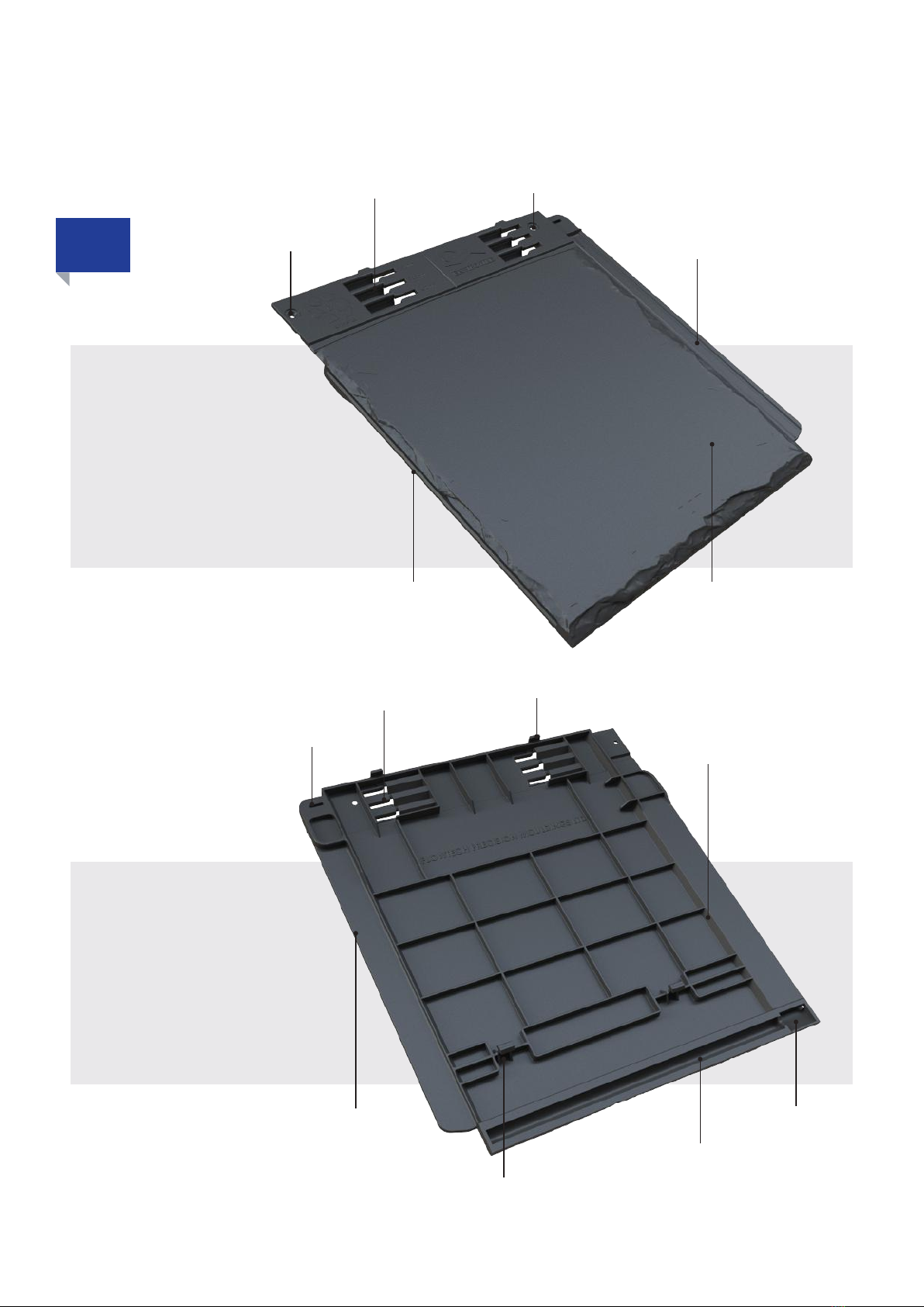
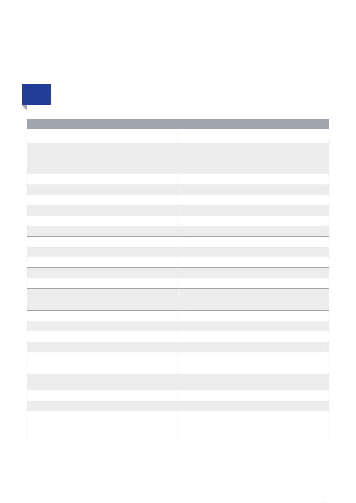
Envirotile offers unrivalled technical performance along
with excellent eco-credentials. It’s precision crafted design
fully utilises the latest in recycled material technology which
ensures every roof tile meets the strictest level of quality.
The lightweight Envirotile Interlocking Roof System must be
installed in full compliance with recommendations outlined
in BS:5534-2014 code of practice for slating and tiling
and BS:8000-6-1990 code of practice for workmanship on
building sites for slating and tiling of roofs and cladding.
ENVIRONMENTALLY SUSTAINABLE LEADING PERFORMANCE
ENVIROTILE: BENEFITS THAT REDUCE OVERALL BUILDING COSTS
ENVIROTILE: GENUINELY SUSTAINABLE
ENVIROTILE: MORE SECURE

2| ENVIROTILE INSTALLATION GUIDE 3
1. TECHNICAL FEATURES
1.0
TOP VIEW
UNDERSIDE VIEW
Nail or Screw Position for LHS verge
secondary xing (K)
Interlocking Insert (A)
Underside Joining Clip (E)
Drip Channel (G)
Drainage (I)
Slate nish aesthetics
also provides non slip
assistance with foothold
Interlocking Open Groove (C)
Nail Fixing Aperture (D)
Gauge Settings (B)
Gauge Grooves (B)
5mm Expansion line setting (J)
Note: Standard nish tile also available
Detachable Nibs (F)
Strengthening Rib
features (H)

4| ENVIROTILE INSTALLATION GUIDE
2. AT A GLANCE TECHNICAL INFORMATION
2.0
Envirotile Composition Manufactured to BS:9001 for quality assurance. Injection moulded
using 100% of UK reliably sourced reprocessed Polypropylene
Roof Tile/Slate colour
Slate range:
Terracotta/Brown/Slate Grey/Anthracite Grey
Standard range:
Terracotta/Brown/Slate Grey/Anthracite Black
Gauge Recommended Setting Head Lap
12.5° - 22.5° (Low Pitch) 250mm Gauge 110mm
22.5° - 90° 265mm Gauge 95mm
22.5° - 90° 280mm Gauge 80mm
Coverage per Square Metre
At 280mm gauge 11.9 tiles
At 265mm gauge 12.6 tiles
At 250mm gauge 13.4 tiles
Envirotile Weight (single tile) 645g
Easy to carry pack (10 tiles) 6.45 kg
Suitable Roof Pitch 12.5° to 90° (vertical)
Fixing batten to rafter - recommendations
Graded battens to be used
38mmx 25mm for 450mm rafter centres
50mm x 25mm for 600mm rafter centres
Batten xing nails to BS:5534 - 14 65mm x 3.35mm
Envirotile xing to BS:EN1202-3 Every tile to be secured and xed
On normal pitch of 25° or over 30mmx 3.35mm stainless steel annular ring shank
Low pitch xing from 12.5° to 25° 30mm x 4mm countersunk stainless steel screw
Envirolay Bre Certied 13859-1 and BS:EN 12310-1
Recommended droop allowance of 15mm between rafter centres x
3 recommended nail xings per rafter
overlap 150mm for each course
Bond A half bond using a cut half starter tile at verge - similar in appear-
ance to a double lap tile or slate bond when laid to roof
Expansion gap between tiles 5mm (moulded guide line to assist installer)
Screw Type on shallow pitches Always use S/Steel screw xings on roof pitches below 25°
Cutting of Envirotile
No dust pollution is emitted during the cutting process, the use of
a chalk line to determine straight edge cutting is strongly recom-
mended and will be extremely benecial in use with valley, hip and
gable end detail

4| ENVIROTILE INSTALLATION GUIDE 5
Ventilation:
Universal fascia products used in conjunction with the Envirotile
roof system must conform to recommendations provided in
BS:5250/2016.
At fascia on roof pitches above 15° 10,000mm of airow per metre
run is recommended for use.
On roof pitches below 15° 25,000mm of airow per metre run is
required for use.
Packaging
720 x single tiles supplied shrink wrapped on a wooden pallet
consisting of 72 packs of 10 x tiles.
280 x double tiles consisting of 28 packs of 10 x tiles
Storage conditions Dry at surface area required for storing pallets
Fixing in freezing conditions Roof tile installation not to be carried out below 4°C
Recommended universal dry x products to be used GRP Valley trough
GRP Abutment Flashing
Dedicated Envirotile dry x verge and ridge products Must be genuine Deeplas manufactured and supplied parts
Deeplas reserves the right to alter any of the elements quoted in the above specication without prior notice. Please note that
the above information is given in good faith and should be considered as a guide only, if any values in this specication are of
critical importance then we strongly recommend the user arranges independent testing themselves. Test methods mentioned
are considered as guides only, actual methods may differ slightly in practice. Suitability of the product for all applications is at the
discretion of the user, as are any potential patent infringements relating to specic applications.

6| ENVIROTILE INSTALLATION GUIDE
3. ENVIROLAY TEST RESULTS
3.1 ENVIROLAY TECHNICAL INFORMATION
Envirolay is suitable for use in all 5 UK wind
pressure zones
Summary of test results for wind uplift resistance
of Envirolay underlay to BS 5534-2014 Annex A Conducted
by Bre Report number : P101133-1000 Issue 2
* Maximum continuous operating
temperature is 220°C, short periods
up to 250°C
Base fabric will withstand 550°C
(unstressed), melting point > 800°C.
DUO PLUS TAPE (ENVTAPE)
Use Duo Plus tape to seal the
overlap layers to provide added
protection against high wind uplift
loads during full exposure.
Fire Resistant
For Use in all UK Zonal Areas 1-5
Fully Bre Tested to BS5534 Annex A
Fully Exova Tested with Envirotile to DD CEN/TS 1187 test4 –Brooft4
Suitable for use on all Cold or Warm Roof type Structures
3.0
3.1
Geographical Wind Zone
Underlay Name 345mm Batten Gauge
Battened Lap
250mm Batten Gauge
Battened Lap
345mm Batten Gauge
Taped Lap
Deeplas Envirolay Zones 1 to 5
>2040 Zones 1 to 5 Zones 1 to 5
>4500
Finished Fabric Units Value Tolerance
Weight g/m2475 ±5%
Thickness mm 0.4 ±5%
Useable width (standard) mm 1300 ±5%
Roll Length (standard) mtr 25
Maximum operating temp. °C 220*
Colour/Description Waterproof/Grey coating both sides
Roll Weight (standard) kg 15.4 ±5%
Base Fabric Construction Units Value Tolerance
Weight g/m2425 ±5%
Weave pattern 4H Satin
Construction
Warp per cm 19.2 ±5%
Weft per cm 11.2 ±5%
Yarn count
Warp Tex EC9 136
Weft Tex EC9 136
Treatment/Coating Details Units Value Tolerance
Weight g/m250 ±10%
25g/m2Grey silicone on each side.

6| ENVIROTILE INSTALLATION GUIDE 7
4. INSTALLATION GUIDE FOR ENVIROTILES
4.0
For Hipped roof see pages 28 to 38
This installation guide is aimed at all new users of the Envirotile system - builders, installers and self builders. It is not intended as a
guide to general roof construction and examples given here have been created to demonstrate how the Envirotile system is tted.
Note that this guide assumes the use of product supplied by Deeplas. Whilst some products can be replaced with generic branded
products for the same application all product warranties are based on the installer tting Deeplas branded products.
Hipped Installation
For Gable and Abutment wall roofs see pages 8 to 27
Gable Wall InstallationAbutment Wall Installation

For abutment walls install the rafter roll
out tray and x to the end rafter
By adding a continuous roll out rafter
tray to your roof it will provide a clear
ventilation path to the underside of the
roofers underlay Envirolay (ENVIROLAY).
Ax the roll over and between
independent rafters along the whole
width of the roof (as illustrated) position
directly behind the ventilated fascia board
area.
It is recommended that a minimum
of 2 galvanised clout nails are used to
permanently x the continuous roll out
rafter tray to each independent rafter.
VENTILATION: FITTING THE CONTINUOUS ROLL OUT RAFTER EAVES VENT TRAY
Prior to beginning the roof it is critical that the roof area that is to be covered with roof
tiles is level and square before installation.
Always provide the correct ventilation requirements at the
eaves sot area.
Note: The roof pitch governs the recommendations of airow
per meter run required, on rafter pitches above 15 degrees
it will require 10,000 mm/m of airow per meter run and on
pitches below 15 degrees 25,000mm of airow per meter run
is required for conformity to recommendations outlined in
BS5250/2016.
90 degrees
level
Note that the roof images provided as content material are
indicative examples of standard roof types provided to assist
the installer with a visual perspective of the different stages of
the Envirotile installation process.
level
90 degrees
90 degrees
90 degrees
8| ENVIROTILE INSTALLATION GUIDE
5. SETTING UP
5.0

8| ENVIROTILE INSTALLATION GUIDE 9
6. VENTILATION
6.0
Saddle the fascia board the full width of the
roof with lengths of specically designed
Deeplas felt support trays. Align and ax to
independent rafter centres using galvanised
clout nails.
Butt up against the abutment wall with the
felt support tray.
Note : At ends overlap each universal felt
support tray by a minimum of 100mm to
ensure water tightness is maintained.
SADDLE AND FIXING OF FELT SUPPORT TRAYS

10 | ENVIROTILE INSTALLATION GUIDE
7. EAVES STARTER RAIL
7.0
For abutment wall roofs ensure that the
nal Starter Rail located next to the wall
provides a gap of 40mm away from the
wall edge.
DO NOT FIT THE LAST STARTER RAIL AT
THIS STAGE - REFER TO ABUTMENT WALL.
Starting at the right hand gable end verge,
run through the full roof width with eaves
bar/starter rails ENVEB then mechanically
x with stainless steel screws.
Saddle the felt support tray before xing
permanently.
Note: Use the pronounced front edge
lip located on the Eaves Starter rail and
saddle the shaped contours of the felt
support tray using the designated screw
apertures to screw x into the head of the
fascia.
Please note that the Eavebar/Starter
Rail ENVEB is an integral part of the
Envirotile Roof System and has been
specically designed to provide both
the secure patented holding features
for the rst course of roof tiles as well
as added ventilation to the underside of
the roof covering which allows for built
up condensation and moisture to escape
through the viaduct channels.
MECHANICALLY DRY FIXING VENTILATED EAVES BAR/STARTER RAILS
DO NOT FIT LAST STARTER RAIL YET

10 | ENVIROTILE INSTALLATION GUIDE
8. ENVIROLAY INSTALLATION
8.0 ENVIROLAY INSTALLATION PROCEDURE
Please note that only Envirolay (ENVIROLAY) is
approved for full use with the Envirotile Roof
System in conformity to Fire Standard BS:476-3.
If another universal type of underlay is used for
Envirotile installation on a cold roof type it will
contravene Deeplas’s guarantee and roof performance
and all warranties will be considered null and void.
Warm roof types are exempt and can, subject to
design, use other types of underlay provided that
the warm roof system is fully approved for full use
in conformity with the latest revised and updated
building regulations for 2020 onwards.
Starting at the right hand gable end roll out and x
to the centre of rafters a single course of Envirolay
(ENVIROLAY) to the full roof width to be battened;
xing and securing the roof underlay at rafter
centres with clout nails as you go along. A 15mm
sag/drop is required between rafters to allow for
interstitial condensation to run down the roof
below xed battens. Overlap the eaves/felt support
trays by a minimum distance of 100mm for the
rst course of underlay (illustrated).
Cut the underlay straight at gable ends with a
sharp knife or robust pair of scissors in line with
the gable end edge.
Always overlap each Envirolay course by a
recommended minimum distance of 150mm.
Use Duo Plus tape (ENVTAPE) to seal the overlap
layers to provide added protection against high
wind uplift loads during full exposure.
DUO PLUS TAPE (ENVTAPE)
ENVIROLAY (ENVIROLAY)
11
100mm min
150mm min
Always provide a 10-15mm
sag between rafter centres to
allow for built up moisture
content to run downwards

12 | ENVIROTILE INSTALLATION GUIDE
Always leave a 25mm gap each side of
the rafter ends at apex.
Note: The gap provided at apex will
provide the area for rising interstitial
moisture and condensation to escape
through the ventilated Envirotile main
roof ridge system.
Run the Envirolay to the wall face and
provide an uplift of material of at least
150mm. Use Duo Plus Tape ENVTAPE to
seal the overlap layers.
25mm
8. ENVIROLAY INSTALLATION
8.1 ENVIROLAY RIDGE DETAIL
ENVIROLAY ABUTMENT WALL DETAIL
Uplift edge
150mm min

12 | ENVIROTILE INSTALLATION GUIDE 13
The Envirotile system relies upon the rst course being an accurate gauge setting and bench mark for penultimate courses
Using a standard single Envirotile as (illustrated) will determine the location of the rst bottom eaves batten.
At the rst rafter lay the tile
at onto the pitched rafter as
illustrated.
Repeat the process for the left hand edge, then provide a chalk line along the full
width of the roof.
Fix the rst course of battens using the
marked line.
PLEASE NOTE: IT IS CRITICAL THAT THE
FIRST BATTEN IS LEVEL!
Take an Envirotile and push and clip
the lower joining clip (E) into the
eaves/starter rail as illustrated.
At the rst gable end right hand
rafter make a pencil mark at the top
leading edge of the tile, as illustrated.
Note that the distance between the
leading edge of the tile should be
located approximately centre of the
xed gutter by a distance of 40-50mm
40-50mm
9. FITTING BATTENS
9.0 INSTALLING THE FIRST COURSE OF BATTEN
Fix the rst batten course so the top
edge is along the marked line
Note: Once the line is marked, check that
it is level and perfectly straight

14 | ENVIROTILE INSTALLATION GUIDE
Where roof angle is below
22.5° the batten/tile gauge
setting required is 250mm.
Where roof angle is over 22.5° the
batten/tile gauge setting can be
250, 265 or 280mm depending on
the installation.
Referring to the illustrations, measure the distance between the top apex nal course batten (top edge) to
the rst bottom eaves course batten (top edge) and from that dimension deduct 35mm.
The result is the distance between the top batten and the rst course of batten using
the top edges to measure from.
Use this distance to calculate the number and spacing of battens,
being careful to note the minimum batten gauge required (see below).
N.B Always use a chalk line to establish the gauge for
each batten course, the top edge of the batten is
mechanically xed to the underside of the chalk line.
Fix the battens, leaving out the nal top course.
Note: The installer may need to adjust the batten gauge settings
to accommodate the rafter dimensions. This is achieved by
reducing the gauge to either a 265mm or 250mm gauge
setting to assist the nal position of the top course of batten.
Alternatively, set out the battens to your preferred gauge and
ax a short nal batten course where the installer will have to
simply cut and shorten the top course of tiles as illustrated on
page 18.
35mm
9. FITTING BATTENS
9.1 BATTEN SETTING OUT AND FIXING
Roof angle
Batten gauge
Distance along roof edge

14 | ENVIROTILE INSTALLATION GUIDE 15
Ensure that there is a gap of at least
25mm to ensure good ventilation
Use the top batten as a cutting edge to
trim off any excess Envirolay to ensure
that the ridge ventilation path is clear
Fix the apex batten to the rafters as shown above Then x the top batten course, 35mm down from the rafter apex
9. FITTING BATTENS
9.2 RIDGE STRUCTURE
35mm
Note that the rafter straps are usually
supplied at and need to be bent to shape.
Before the last top eaves course batten is xed, x a 50mm x 50mm bedded batten above the rafters using rafter straps
(non-supplied).

16 | ENVIROTILE INSTALLATION GUIDE
ABUTMENT WALL RIDGE
STRUCTURE DETAIL
ABUTMENT WALL BATTEN DETAILS
At abutment walls t battens so that there is an 80mm
minimum clearance between the batten and the wall face. Allow 80mm clearance at the ridge batten.
Cut off the TOP EDGE of the tile so that it is ush with the top
edge of the top batten
9. FITTING BATTENS
9.3 ALTERNATIVE TOP BATTEN SETTING OUT
Envirotiles can be cut with a hand saw very easily so an alternative option for the batten setting out is to set out the battens up the
roof face by the recommended gauge (see page 16) then t the top batten course so that the gauge is different. For the top row of
tiles the installer can then cut off the TOP EDGE of the tile so that it clips into the lower tile and lines up with the top batten edge.
Final batten row can be
reduced to t, but min
gauge is 150mm
Batten/tile gauge setting 250, 265 or
280mm depending on the roof angle
80mm min 80mm min
Allow 80mm clearance between the end of the ridge
batten and the wall face. Ensure that the ridge batten
is xed securely at the end rafter

16 | ENVIROTILE INSTALLATION GUIDE 17
At the gable ends slide a roof tile (rst roof tile) into the
eaves/starter rail at the gable end as shown.
Simply position the end of the continuous dry verge unit
directly in line and ush with the bottom edge of the
overhanging roof tile and place the inner sleeve directly onto
the exposed batten ends that have been cut ush with the
gable roof edge.
Fix with 30mm stainless steel screws downwards into the top
of the battens making sure the dry verge unit is perfectly in
line with the verge.
Fix a bracket clip, if required, with screw xings ENVDVB,
to join lengths of continuous dry x verge when rafters are
longer than 3m in length.
At the apex centre mitre cut and abut to the continuous dry
verge unit to the correct pitch angle in readiness for the gable
end cap to be xed.
Note: It is recommended that fascia board is used to
envelope/overlap the continuous dry verge at exposed gable
ends. This provides improved aesthetics as well as additional
protection against severe wind uplift.
To nish gable ends it is recommended that the continuous dry x verge (ENV3MDV) is
used. This is tted over the top of the battens and runs along the top edge of the end rafters
at gable ends. Use dry verge brackets (ENVDVB) to join lengths of dry verge if required.
10. DRY VERGE INSTALLATION
10 INSTALLING THE CONTINUOUS DRY VERGE
Fit dry verge to
edge of tile

18 | ENVIROTILE INSTALLATION GUIDE
Ensure that you clip the tiles into the right slots depending on the batten gauge used.
Each tile has two detachable nibs (F) at the top. These are used to hook the tile over the batten. When a batten has been tted
out of alignment or there has been some movement after tting, the installer can break the nibs off as required if they nd that
the nibs no longer hook over the batten.
Detachable nib F
Detachable nib F
11. INSTALLING THE ENVIROTILES
11 INSTALLING THE ROOF TILES - KEY POINTS
Envirotiles are very easy to install, but it will help to familiarise yourself with the important design features of the tile to ensure that
you understand how the tiles x together.
Envirotiles are laid using the standard 3 step layout procedure. This is detailed on page 22.
Always lay tiles in half bond. Envirotiles are clipped together using the two clips on the underside at the
bottom of the tile (E) clipping into the slots at the top of the tile on the course
below (B). Note that the tile must be aligned, then pushed down, then the tile is
slid to the right to lock into the clip. The sliding action also locks the connecting
strip into the adjacent tile slot.
Clip E
Clip E
Slot B
Slot B
250/265/280mm

18 | ENVIROTILE INSTALLATION GUIDE 19
IMPORTANT FEATURES
Prior to commencement of roof tile installation mark out with a pencil where
the tile pack rows are to be conveniently and evenly placed and spaced.
Provide enough room between the rows of stacked, packed tiles to be able
to work freely and without hindrance.
Only load enough packs of tiles to the roof area that the installer feels will be
used during the period of tile xing/installation.
Unused packs of tiles should not be left on exposed roof areas overnight or
for any long period as a preventive measure against damage/injury caused by wind loads.
A single pack of single roof tiles covers an approximate area of 0.8m²
Note: During and after the tile installation remove and regularly collect all loose pack strapping and place away from the roof
working area as a preventive trip hazard.
Always lay the roof system to half bond. Always provide a 5mm gap between tiles
to accommodate expansion/contraction.
The roof tiles incorporate design features that maintain straight
plumb lines to ensure straight vertical bonding.
Each roof tile has an embossed centre mark line located at the
head of each roof tile this mark provides the correct positioning
for the purpose of cutting half tiles.
Tiles can be cut with a hand saw
Note: An embossed 5mm marker/guide line
is etched onto the tile interlocking insert
n to assist the installer with spacing.
Each roof tile is designed to be permanently xed and secured in
place with neighbouring roof tiles and onto batten at 8 separate
points.
One 32mm x 4.2mm Stainless Steel Pozi Pan Self Tapping
(ENVSCREW32) or driven nail required to x a single tile. On
gable ends or abutment walls 2 xings are required per tile.
Tiles can be freely traversed when secured and installed
permanently onto roof areas.
11. INSTALLING THE ENVIROTILES
11.1 BEFORE YOU START
xing

20 | ENVIROTILE INSTALLATION GUIDE
Take a new tile and clip into the
starter rail, hook over the batten,
then slide this tile into the end tile
so that the connecting strip ts into
the left hand slot of the tile. Push
together ensuring there is a 5mm
space between the top faces of the
tiles.
The spacing between tiles can be
adjusted to allow for course length
(see next stage), but ensure that the
minimum spacing is 5mm, and that
the xing hole (A) comes over slot (B)
when the tiles are joined.
Then, slide this tile into the dry verge
as shown.
Next, clip this cut tile into the starter rail, as
shown, and rest the top over the batten - using
the lugs as guides to hook on.
Take the rst tile and cut off the right
hand connecting strip using a hand
saw - see above.
Use a full tile to start and cut off the
right hand connecting strip.
11. INSTALLING THE ENVIROTILES
11.2 INSTALLING ROOF TILES ONTO THE EAVES BATTEN
Starting from right to left without xing, run through the full length of the rst eaves/course with tiles to ascertain the correct
location and permanent xture position of the rst course of tiles.
Slot B
Hook over batten
Clip into starter rail
Hole A
Table of contents
Other Deeplas Outdoor Furnishing manuals
Popular Outdoor Furnishing manuals by other brands

Jungle Gym
Jungle Gym Jungle Cabin Assembly instructions and owner's manual

New England Arbors
New England Arbors The Westwood Arbor Assembly instructions

hanit
hanit EIFEL Assembly instructions

Safavieh Outdoor
Safavieh Outdoor PAT7005 quick start guide

Safavieh Outdoor
Safavieh Outdoor PAT2500 manual

CAZEBOO
CAZEBOO SAO 300S300 manual