degdrive DGI900 User manual

User Manual
DGI900

1
Preface
DGI900 series is the newgeneration products to meet general purpose and special technical
demand. The new designed sensorless vector control performance of DGI900 inverter have
improved the reliability at low speed, the overload capacity at low frequency and high control
precision at open loop tension control mode. Its function of anti-trip and strong adaptability to
worse grid, temperature, humidity and dust make it meet the high-performance requirement
of the customer application.
DGI900 series inverters built-in RS485 interface which can use software upload, download
and monitoring the parameter of inverter. Built-in PID, 16 multi-speed, traverse control can
realize various complicate high-accuracy drives and widely apply in Textile, paper industry,
machine tool, package, printing, pump and fan.
This manual provides installation and configuration, parameters setting, fault diagnoses and
daily maintenance and relative precautions to customers. Please read this manual carefully
before the installation to ensure a proper installation and operation and high performance of
DGI900 series inverters.
DANGER:indicates the situation in which the failure to follow operating requirements
may result in fire or serious personal injury or even death.
CAUTION: indicates the situation in which the failure to follow operating requirements
may cause moderate or slight injury and damage to equipment.

2
Contents
Preface ············································································································1
Chapter 1 Precautions·······················································································5
1.1 Safety Precautions·························································································5
1.2 Precautions for use························································································8
1.3 Disposal considerations ················································································10
Chapter 2 Product Introduction········································································· 11
2.1 Naming rules······························································································ 11
2.2 Nameplate information·················································································· 11
2.3 Series and Models·······················································································12
2.4 Specifications ·····························································································13
2.5 Products apperance·····················································································16
2.6 Installation size ···························································································17
2.7 Optional Parts·····························································································21
Chapter 3 Installation and Wire Connection························································23
3.1 Mechanical installation··················································································23
3.2 Standard wiring···························································································24
3.3 EMC Installation Instruction ···········································································35
Chapter 4 Operation and operation examples ·····················································39
4.1 Initial power-up ···························································································39
4.2 Inverter operation ························································································40
4.3 Keypad introduce·························································································42
4.4 Display status ·····························································································45
4.5 Keypad operation ························································································48
Chapter 5 Function Code Table········································································· 51

3
5.1 Property description·····················································································51
5.2 Function code table······················································································51
Chapter 6 Detailed Function Parameter Description·············································91
Group P0 Standard Function Parameter································································91
Group P1 Start/Stop Parameter ········································································· 101
Group P2 Auxiliary Functions ············································································ 106
Group P3 Input Terminals··················································································118
Group P4 Output Terminals··············································································· 132
Group P5 V/F curve parameters ········································································ 140
Group P6 PID Function parameters···································································· 145
Group P7 Operation Panel and Display······························································· 152
Group P8 Motor Parameters ············································································· 155
Group P9 Vector Control Parameters·································································· 158
Group PA Fault and Protection ·········································································· 164
Group Pb Multi-Reference and Simple PLC Function ············································· 174
Group PC Communication Parameter·································································177
Group Pd Function Code Management ······························································· 177
Group PE Swing Frequency, Fixed Length and Count············································· 178
Group PF AI/AO Correction andAI Curve Setting ·················································· 182
Group E0 Ser function code parameter································································ 184
Group E9 Protection function parameter······························································ 185
2nd, 3rd, and 4th motor parameters (E3, E4, E5 groups)········································· 188
Monitoring parameter group-operation parameter monitoring (group b0))·················· 188
Chapter 7 Fault Diagnosis and Processing······················································· 189
7.1 Failure Phenomena and Countermeasures ····················································· 189
7.2 Fault Record Query···················································································· 193
7.3 Fault Reset ······························································································ 193

4
Chapter 8 Maintenance and Maintenance e······················································· 195
8.1 Daily maintenance and Maintenance ····························································· 195
8.2 Periodic Preservation and Maintenance·························································· 195
8.3 Warranty Description·················································································· 196
Chapter 9 Serial Port RS485 Communication Protocol······································· 198
9.1 Communication Overview············································································ 198
9.2 Communication Protocol Description······························································ 198
9.3 Communication Protocol ············································································ 200
Chapter 10 Appendix····················································································· 208
5
Chapter 1 Precautions
1.1 Safety Precautions
The use phase
Safety class
Precaution
Before
Installation
Danger
Do not install the product if the package is with
water, or component is missing or broken;
Do not install the product if the label on the
package is not identical to that on the inverter.
Caution
Be careful of carrying or transportation. Risk of
devices damage.
Do not use damaged product or the inverters
missing component. Risk of injury.
Do not touch the parts of control system with
bare hands. Risk of ESD hazard.
Installation
Danger
Installation base shall be metal or other
non-flammable material. Risk of fire.
Do not install inverter in an environment
containing explosive gases, otherwise there is
danger of explosion.
Do not unscrew the fixing bolts, especially the
bolts with red mark.
Caution
Do not leave cable strips or screws in the
inverter. Risk of inverter damage.
Install the product at the place with less vibration
and no direct sunlight.
Consider the installation space for cooling
purpose when two or more inverters are placed
in the same cabinet.

6
The use phase
Safety class
Precaution
Wiring
Danger
Wiring must be performed by authorized and
qualified personnel. Risk of danger.
Circuit-breaker should be installed between
inverter and the mains. Risk of fire.
Make sure the input power supply has been
completely disconnected before wiring. Failure to
comply may result in personnel injury and/or
equipment damage.
Since overall leakage current of this equipment
may be bigger than 3.5mA, for safety's sake, this
equipment and its associated motor must be well
grounded so as to avoid risk of electric shock.
Never connect the power cables to the output
terminals (U, V, W) of the AC drive. Pay attention
to the marks of the wiring terminals and ensure
correct wiring. Failure to comply will result in
damage to theAC drive.
Install braking resistors at terminals (P+) and (P-
or PB) only. Failure to comply may result in
equipment damage.
Caution
Since all adjustable frequency AC drives from our
company has been subjected to hi-pot test before
delivery, users are prohibited from implementing
such a test on this equipment. Failure to comply
may result in equipment damage.
Signal wires should to the best of the possibility
be away from main power lines. If this cannot be
ensured, vertical cross-arrangement shall be
implemented, otherwise interference noise to
control signal may occur.
If motor cables are longer than 100m, it is

7
The use phase
Safety class
Precaution
recommended outputAC reactor be used.
Failure to comply may result in faults.
Before
Power-on
Danger
Inverter shall be power-on only after the front
cover is assembled. Risk of electrical hazard.
Caution
Verify that the input voltage is identical to the
rated voltage of product, correct wiring of input
terminals R, S, T and output terminals U, V, and
W, wiring of inverter and its peripheral circuits,
and all wires should be in good connection. Risk
of inverter damage.
After Power-on
Danger
Do not open the cover after power. Rick of
electrical hazard.
Do not touches any input/output terminals of
inverter with bare hands. Rick of electrical
hazard.
Caution
If auto tuning is required, be careful of personal
injury when motor is running. Risk of accident.
Do not change the defaults of parameters. Risk
of devices damage.
During
Operation
Danger
Non-professionals shall not detect signals during
operation. Risk of personal injury or device
damage.
Do not touch the fan or the discharging resistor to
check the temperature. Failure to comply will
result in personal burnt.
Caution
Prevent any foreign items from being left in the
devices during operation. Risk of device damage.
Do not control start/stop of inverter by ON/OFF of
contactor. Risk of device damage.
8
The use phase
Safety class
Precaution
Maintenance
Danger
Maintenance and inspection can only be
performed by professionals. Risk of personal
injury.
Maintain and inspect devices after power is off.
Risk of electric hazard.
Repair or maintain the AC drive only ten minutes
after theAC drive is powered off. This allows for
the residual voltage in the capacitor to discharge
to a safe value. Failure to comply will result in
personal injury.
All pluggable components can be inserted or
pulled out only when power has been turned off.
Set and check the parameters again after theAC
drive is replaced.
1.2 Precautions for use
When using the DGI900 series inverter, please pay attention to the following points:
1.2.1 Constant torque and low speed operation
When the inverter is running with a normal motor for a long period of low speed, the heat
dissipation effect will be deteriorated, which will affect the life of the motor. If you need
low-speed constant torque for long-term operation, you must use a dedicated inverter
motor.000000000000000000000000000
1.2.2 Confirmation of motor insulation
When applying the DGI900 series inverter, please confirm the insulation of the motor before
using the motor to prevent damage to the equipment. In addition, please check the insulation
of the motor regularly when the environment of the motor is bad, to ensure the safe operation
of the system.
1.2.3 Negative torque load
For situations such as lifting the load, there is often a negative torque, and the inverter will
trip if an overcurrent or overvoltage fault occurs. In this case, the optional braking resistor
9
should be considered.
1.2.4 Mechanical resonance point of the load device
The inverter may encounter the mechanical resonance point of the load device within a
certain range of output frequency, and must be avoided by setting the jump frequency.
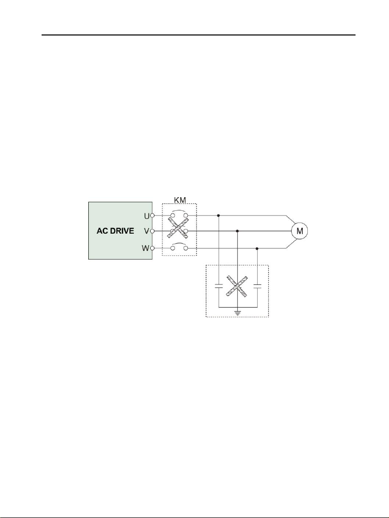
1.2.5 Capacitance or varistor for improving power factor
Since the output voltage of the inverter is pulse wave type, if the output side is equipped with
a capacitor with improved power factor or a varistor for lightning protection, it will cause the
inverter to trip or damage the device. Be sure to remove it, and it is recommended not to be
on the output side. Add switching devices such as air switches and contactors, as shown in
Figure 1-1. (If the output of the inverter must be zero when the output side switch device is
activated)
Figure 1-1 Disabling the capacitor at the output of the inverter
1.2.6 Derate at Basic frequency setting
When the fundamental frequency setting is lower than the rated frequency, please pay
attention to the derating of the motor to avoid overheating of the motor.
1.2.7 Operating at frequencies above 50Hz
If it is operated above 50 Hz, in addition to considering the vibration and noise of the motor, it
is necessary to ensure the speed range of the motor bearings and mechanical devices.
1.2.8 Electronic thermal protection value of the motor
When the adapter motor is selected, the inverter can thermally protect the motor. If the motor
does not match the rated capacity of the inverter, be sure to adjust the protection value or
take other protective measures to ensure the safe operation of the motor.
10
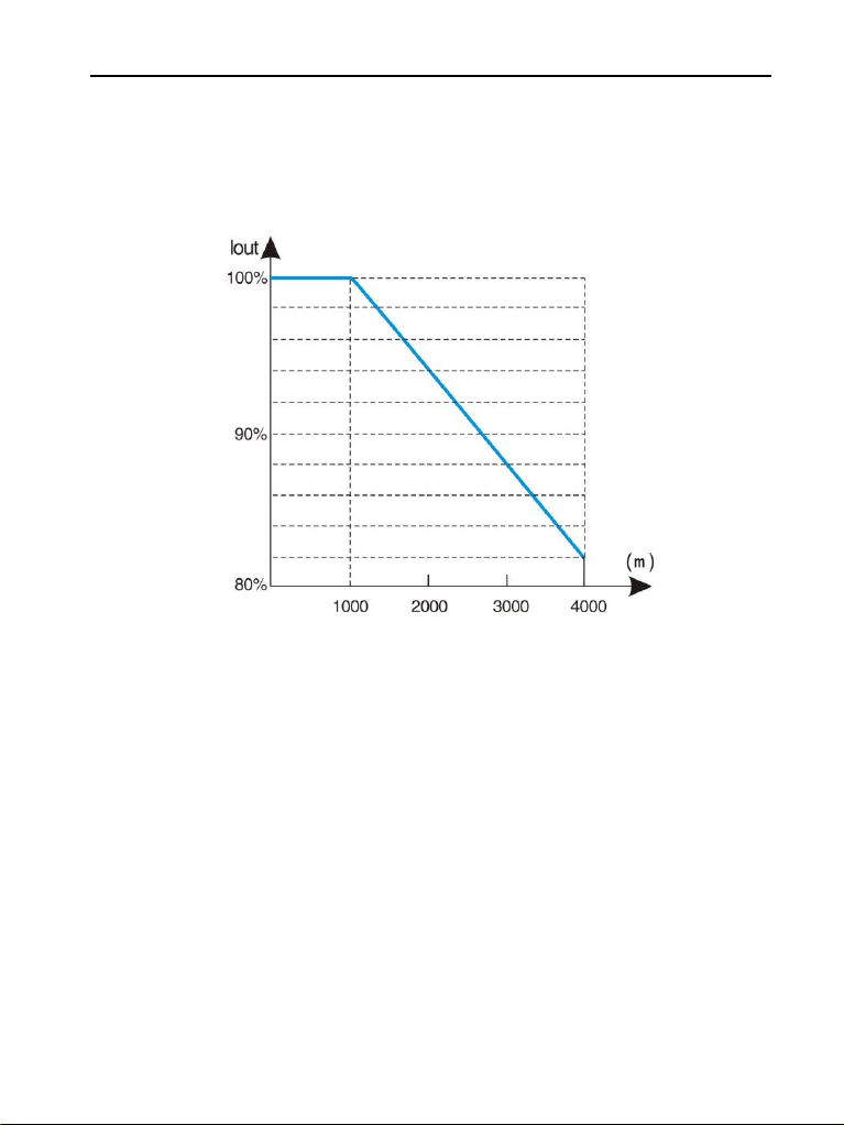
1.2.9 Altitude and derating
In areas where the altitude is more than 1000 meters, the heat dissipation effect of the
inverter is deteriorated due to the thin air, and it is necessary to derate the use. Figure 1-2
shows the relationship between the rated current of the inverter and the altitude.
Figure 1-2 Inverter rated output current and altitude derating diagram
1.2.10 About the degree of protection
The protection level IP20 of the DGI900 inverter refers to the degree of protection achieved
when the status display unit or keyboard is selected.
1.3 Disposal considerations
When scrapping the inverter, please note:
The electrolytic capacitor of the main circuit and the electrolytic capacitor on the printed
circuit board may explode when incinerated. Poisonous gas is generated when plastic parts
are incinerated body. Please treat as industrial waste.

11
Chapter 2 Product Introduction
2.1 Naming rules
2.1 Nameplate information
Below the right side panel of the inverter, a nameplate indicating the inverter model and
rating is attached. The meanings are as follows:
Voltage
Code
220V
2
380V
4
Input voltage
Code
Single phase
S
Three phases
T
Code
Inverter type
G
Constant torque
P
Pump& Fan
Code
Power rate
0007
0.75KW
0015
1.5KW
0075
7.5KW
Fig 2-1. Models description
Abbreviatio
n
DGI900-4 T 0015 G

12
Fig 2-2. Name Designation Rules
2.3 Series and Models
Voltage
level
Model
Rated
capacity
(KVA)
Rated
output
Current
(A)
Applicable
Motor
(KW
)
GType
PType
380V
Three
phase
DGI900-4T0007G
DGI900-4T0015P
1.5
2.5
0.75
DGI900-4T0015G
DGI900-4T0022P
2.5
4.0
1.5
DGI900-4T0022G
DGI900-4T0022P
3.0
6.0
2.2
DGI900-4T0037G
DGI900-4T0037P
5.9
9.6
3.7
DGI900-4T0055G
DGI900-4T0055P
8.5
14.0
5.5
DGI900-4T0075G
DGI900-4T0075P
11
17.0
7.5
DGI900-4T0110G
DGI900-4T0110P
17
25
11
DGI900-4T0150G
DGI900-4T0150P
21.7
32
15
DGI900-4T0185G
DGI900-4T0185P
25.7
39
18.5
DGI900-4T0220G
DGI900-4T0220P
29.6
45
22
DGI900-4T0300G
DGI900-4T0300P
39.5
60
30
DGI900-4T0370G
DGI900-4T0370P
49.4
75
37
DGI900-4T0450G
DGI900-4T0450P
60
91
45
DGI900-4T0550G
DGI900-4T0550P
73.7
112
55
DGI900-4T0750G
DGI900-4T0750P
99
150
75
DGI900-4T0900G
DGI900-4T0900P
116
176
90
DGI900-4T1100G
DGI900-4T1100P
138
210
110
DGI900-4T1320G
DGI900-4T1320P
167
253
132
DGI900-4T1600G
DGI900-4T1600P
200
304
160
DGI900-4T1850G
DGI900-4T1850P
234
355
187
DGI900-4T2000G
DGI900-4T2000P
248
377
200
DGI900-4T2200G
DGI900-4T2200P
280
426
220
DGI900-4T2500G
DGI900-4T2500P
318
474
250
DGI900-4T2800G
DGI900-4T2800P
342
520
280
DGI900-4T3150G
DGI900-4T3150P
390
600
315
13
Voltage
level
Model
Rated
capacity
(KVA)
Rated
output
Current
(A)
Applicable
Motor
(KW
)
GType
PType
DGI900-4T3500G
DGI900-4T3500P
435
660
350
DGI900-4T4000G
DGI900-4T4000P
493
750
400
DGI900-4T4500G
DGI900-4T4500P
560
850
450
DGI900-4T5000G
DGI900-4T5600P
625
860
500
DGI900-4T5600G
DGI900-4T6300P
691
990
560
DGI900-4T6300G
DGI900-4T7100P
770
1100
630
2.4 Specifications
Items
Specifications
Input
Rated Voltage
Three phase 380V / 415V / 440V/460V; 50Hz/60Hz
Range
Voltage: ±20% voltage unbalance rate:<3%; frequency:
±5%
Output
Rated voltage
0~380V / 415V / 440V/460V
Frequency
range
0Hz~5000Hz
Frequency
resolution
0.01Hz
Overload
ability
150% rated current for1minute, 180% rated current for3
seconds
Control function
Control
function
Torque control
accuracy
±5%(FVC)
Control mode
V/F, Sensorless vector control (SVC), Speed Sensor vector
control (FVC)
Frequency
accuracy
Digital setting: The highest frequency×±0.01% Analog
setting: The highest frequency ×±0.2%
Frequency
resolution
Digital setting: 0.01Hz; Analog setting: The highest
frequency×0.1%
Start
frequency
0.40Hz~20.00Hz
Torque boost
Auto torque boost, manual torque boost 0.1%~30.0%

14
Items
Specifications
V/F curve
Five ways: constant torque V/F curve, 1 kind of user defined
V/F curve ,3 kinds of down torque curve (2.0/1.7/1.2times
the power)
Acc./Dec.
curve
Two ways: linear Acc./Dec., S-curve Acc./Dec.;7 kinds of
Acc./Dec. time, Time unit(minute/second) optional, max.
time: 6000 minutes.
DC braking
DC Braking Frequency: 000Hz~ Max Frequency
Braking Time: 0.0s~36.0s
Braking Action Current Value: 0.0%~100.0%
Energy
consuming
braking
Below 22KW drive built-in energy consuming braking unit,
30-37KW built-in braking unit optional, external braking
resistor is optional.
Jog running
Jog frequency range:0.1Hz~50.00Hz, JOG Acc./Dec. time:
0.1~60.0s
Build-in
Double PID
Easily constitute a close loop control system
Multi-stage
speed
running
Max 16 multi-stage speed running via build-in PLC or
control terminals
Textile swing
frequency
Swing frequency available with preset and central
frequency adjustable
Auto voltage
regulation
Keep a stable voltage automatically when the grid voltage
transients
Auto energy
saving
running
Saving energy by auto optimizing V/F curve according to
the load
Auto current
limiting
Auto current limiting to prevent frequent over current fault
trip
Multi pumps
control
With water supply card, the function can implement multi
pumps constant pressure water supply
Communicati
on
4 field bus: Modbus, Profibus, CANlink, CANopen
Running
command
channel
Control panel: control terminal :serial port :3 channels
switchable

15
Items
Specifications
Running
function
Frequency
setting
channel
Control panel potentiometer setting: ▲、▼control panel
keys setting; Function code setting: Serial port setting;
Terminal up/down setting: Input Analog voltage setting:
Input Analog current setting: Input pulse setting;
Combination ways setting;
Above ways are switchable.
Input channel
8 digital input terminals, 1 of which supports up to 100KHZ
high speed pulse input
2 analog input terminals, 1 support 0~10V voltage input
1 support 0~10V voltage input or 0~20mA current input
Output
channel
1 high-speed pulse output terminal (optional open collector
type), supporting square wave signal output of 0~100Khz
1 digital output terminal
2 relay output terminals (≥5.5kw), one relay below 5.5kw
2 analog output terminals, support 0~20mA current output
or 0~10V voltage output (≥5.5kw 2 terminals) <5.5kw 1
terminal
Control panel
LED digital
display
Display setting frequency, output voltage, output current,
etc.
External
meter display
Display output frequency, output current, output voltage,
etc.
Key lock
All the keys can be locked
Parameter
copy
Function code parameters can be copied between
inverters when use remote control panel
Protection function
Over current tprotection:
overvoltageprotection:undervoltageprotection:overheating
protection: overload protection, etc.
Input phase loss protection ( model>2.2kw)
Optional parts
Braking unit: remote control panel: cable: panel mounting
feet, etc.
Environment
Environment
Indoors, free from direct sunlight, dust, corrosive gas, oil
mist, steam, water dropper salt, etc
Altitude
Lower than 1000m (derating is necessary above 1000m)
Ambient
temperature
-10℃~+40℃
Humidity
<90%RH, no condensation
Vibration
Lower than 5.9m/s (0.6g)

16
Items
Specifications
Storage
temperature
-20℃~+60℃
Structure
Protection
level
IP20(In the selection of state display unit or the keyboard
state)
Cooling
Forced air cooling
Installation
Wall mounted; Floor mounted
2.5 Products apperance
Fig 2-3 parts of Inverter

17
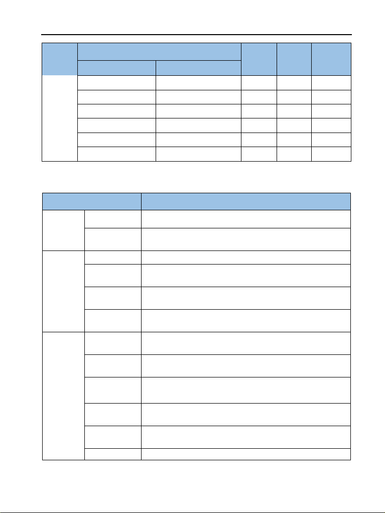
2.6 Installation size
2.6.1 0.75~7.5KW (Wall mounting)
Inverter Model
W1
(mm)
W
(mm)
H1
(mm)
H
(mm)
D
(mm)
Mount
hole
G Type
P Type
DGI900 series/Input voltage: 220V single phase
DGI900-2S0004G
74
85
144
142
113
Φ5
DGI900-2S0007G
DGI900-2S0015G
DGI900-2S0022G
88
98
174
184
135
Φ5
DGI900 series/Input voltage: 380V three-phase
DGI900-4T0007G
DGI900-4T0015P
90
104
177
190
148
Φ5
DGI900-4T0015G
DGI900-4T0022P
DGI900-4T0022G
DGI900-4T0037P
116
130
223
236
175
Φ5
DGI900-4T0037G
DGI900-4T0055P
DGI900-4T0055G
DGI900-4T0075P
155
172
256
271
183
Φ5
DGI900-4T0075G
DGI900-4T0110P
Fig 2-4
18
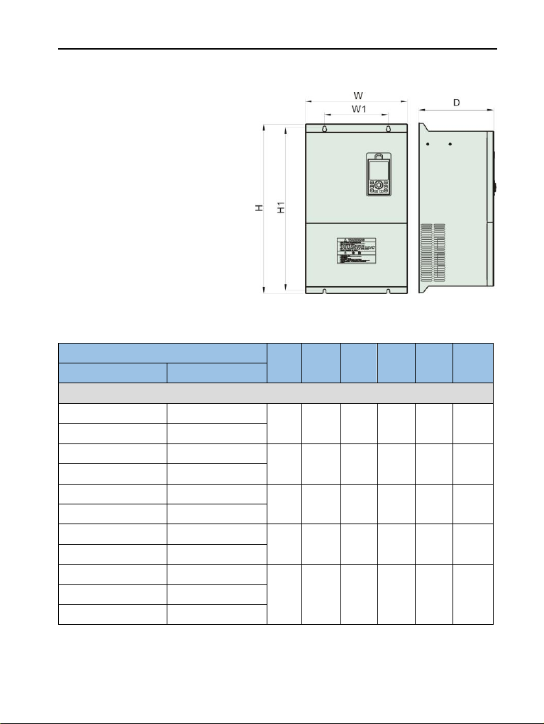
2.6.2 11~90KW (Wall mounting)
Inverter Model
W1
(mm)
W
(mm)
H1
(mm)
H
(mm)
D
(mm)
Mount
hole
G Type
P Type
DGI900 series/Input voltage: 380V three-phase
DGI900-4T0110G
DGI900-4T0150P
170
226
310
325
190
Φ6
DGI900-4T0150G
DGI900-4T0185P
DGI900-4T0185G
DGI900-4T0220P
200
280
427
445
200
Φ6
DGI900-4T0220G
DGI900-4T0300P
DGI900-4T0300G
DGI900-4T0370P
200
320
512
530
235
Φ8
DGI900-4T0370G
DGI900-4T0450P
DGI900-4T0450G
DGI900-4T0550P
250
310
530
555
260
Φ10
DGI900-4T0550G
DGI900-4T0750P
DGI900-4T0750G
DGI900-4T0900P
280
400
620
650
300
Φ14
DGI900-4T0900G
DGI900-4T1100P
DGI900-4T1100G
DGI900-4T1320P
Fig 2-5
19
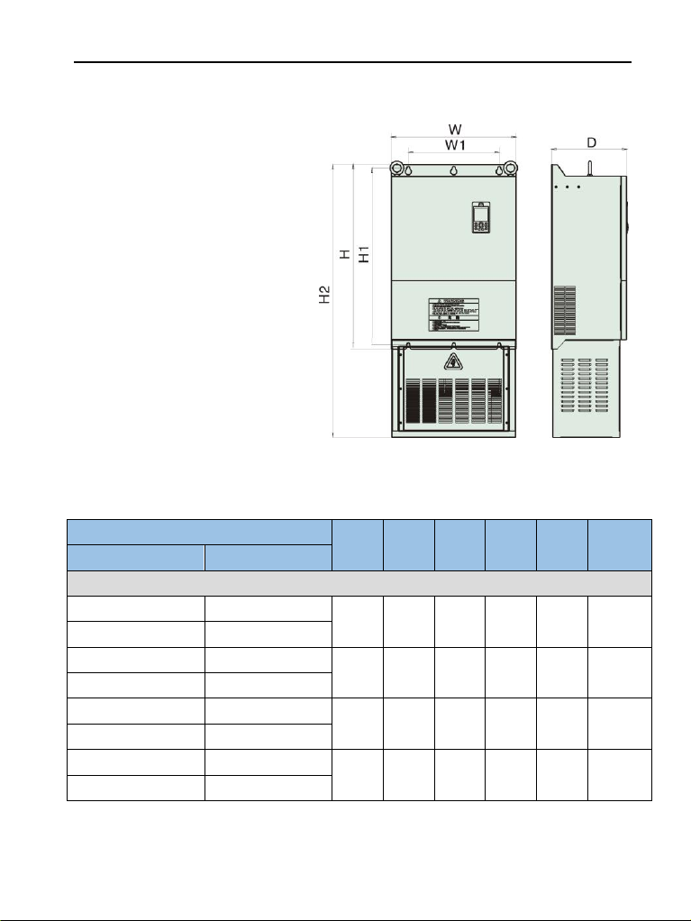
2.6.3 132~250KW (Wall mounting)
Inverter Model
W1
(mm)
W
(mm)
H1
(mm)
H
(mm)
D
(mm)
Mount
hole
G Type
P Type
DGI900 series/Input voltage: 380V three-phase
DGI900-4T1320G
DGI900-4T1600P
280
450
756
790
300
Φ14
DGI900-4T1600G
DGI900-4T1850P
DGI900-4T1850G
DGI900-4T2000P
P P P P G
280
550
776
810
330
Φ14
DGI900-4T2000G
DGI900-4T2200P
PP G
DGI900-4T2200G
DGI900-4T2500P
G
480
640
776
810
350
Φ14
DGI900-4T2500G
DGI900-4T2800P
G
DGI900-4T2800G
DGI900-4T3150P
G
500
720
1150
1200
372
Φ20
DGI900-4T3150G
DGI900-4T3500P
G
Fig 2-6
Other manuals for DGI900
1
This manual suits for next models
61
Table of contents
Other degdrive DC Drive manuals

Popular DC Drive manuals by other brands

Simu
Simu DMI 6 Original instructions

Bodine
Bodine BSL06T3FL installation instructions

Bosch
Bosch Active Line Plus BDU 350 Original operating instructions

ZF-DUOPLAN
ZF-DUOPLAN 2K800 operating instructions

Siemens
Siemens COMBIMASTER 411 operating instructions

Eaton
Eaton PowerXL DM1 Series Applications manual

Canworld
Canworld CDE360 Series manual

Rockwell Automation
Rockwell Automation Allen-Bradley PowerFlex 700 Series Migration guide

Danfoss
Danfoss VLT DriveMotor FCP 106 installation instructions

GFA
GFA ELEKTROMAT SI 40.24-40,00 installation instructions

gefran
gefran ADV200-HC instruction manual

Eaton
Eaton PowerXL DC1 manual


