45
45
7M
RECEIVER
LED POWER BUTTON
CAUTIONS
1.Before installing the controller, please check if the main power is turned off.
2.Before supplying power, please check if the power switch is selected properly.
3.Aviod installing the controller in a high humid environment to prevent failure.
4.The relay outputs shall be used within the operating limit of the controller as the
specification.
5.Read this instruction carefully to prevent any damage cause by misused will void
the warranty.
SET THE CONTROLLER
16 32 .
Fan allow selection from three speeds or/and auto-fan
Sleep mode available in cooling and heating mode.
Swing control allow to select five different angle of fan outlet louver or swing.
apply to 5-wire/6-wire step motor)
Auto-on Auto-off timer 1 12 hrs.
Power button The power button is on the receiver panel which is used to turn
on/off the power directly in case of a failure of cordless remote Press
this button to turn on the controller, the operating function will remain
the last setting
4-Way control 4-way relay contact only closed in heating mode.
FUNCTION
Cooling When room temp. Set temp., Green LED on and compressor on.
Green LED flashes while compressor delay protection) When room temp.
Set temp. 2 , green LED flashes and compressor off.
Heating When room temp. Set temp., Red LED on and compressor on.
( Red LED flashes while compressor delay protection When room temp.
Set temp. 2 , red LED flashes and compressor off.
Fan If select continuous fan, green LED flashes.
Dehumidifying If select dehumidifying, compressor on 10 min. And off 10 min. In cycle
with low speed fan. When the room temperature is under 16 ,
compressor continuously off.
Sleep After one hour of setting sleep mode, the set temp. will rise 1 automatically in
cooling mode. Reduse 1 in heating mode . After two hours of setting
sleep mode, the set temp. will rise another 1 and remain the latest set temp.
Reduse another 1 in heating mode). The max. set temp. is 30 ; the min.
set temp. is 16
Auto-on/off timer The auto-on/off timer counts once the setting is finished.
Receiver
Command only by cordless remote
Operating mode allow selection from four modes of operation(COOL/HEAT/FAN/
DEHUM.)
Setting range Cooling mode 16 30 ; Heating mode
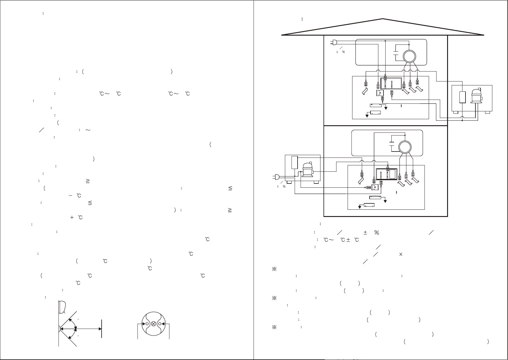
-Version 01 WIRING
Power supply AC110V AC220V 10 , Single phase 50Hz 60Hz
Reading range 5 45 1
Relay outputs compressor output 25A 250VAC
fan speeds outputs 3A 250VAC 3
4-way output 3A 250VAC
SW2 selection (Only apply to DEI-737C)
1. ON with three minutes delay protection ; OFF without three minutes
delay protection Defult
2. ON Continuously Fan Defult ; OFF Fan active as 3-way valve.
2
Short Step motor set on the right. Defult
Open Step motor set on the left. Remove the jumper
ERROR
If sensor fail , red LED flashes rapidly. Check the connection
If interval sensor fail, orange LED flashes rapidly. Return the goods back to factory
Sepcial option
J
SPECIFICATION
Connect to step motor(bule wire on the left side)
AC2
AC1
CN4
CN5 J2
Connect to receiver
MAIN1
LOW MID HI
FAN
MOTOR
AC110V
220V 10
Indoor unit
AC2
AC1
CN4
CN5
J2
MAIN1 LOW MID
HI
FAN
MOTOR
AC110V
220V 10
OUTDOOR
POWER SUPPLY
Outdoor unit
INDOOR
POWER SUPPLY
Compressor
4-way valve
Indoor unit
Outdoor unit
Compressor
4-way valve
Connect to step motor(bule wire on the left side)
Connect to receiver


