Deister electronic Logident UDL 250 User manual

UDL 250
Long Distance Reader
Wiring and Installation
Instructions
V14/05/09
#896108

© Copyright 2009 by deister electronic G bH
All rights reserved. No part of this publicatio may be reproduced, stored i a retrieval
system, or tra smitted, i a y form or by a y mea s, electro ic, mecha ical, photocopyi g,
recordi g, or otherwise, without prior writte permissio of deister electro ic GmbH.
deister electro ic GmbH reserves the right to make cha ges to a y a d all parts of this
docume tatio without obligatio to otify a y perso or e tity of such cha ges.
May 2009 IO/SK/FH/BF
deister electro ic GmbH
Herma -Bahlse Str. 11
30890 Barsi ghause
Germa y
Pho e: +49 (0) 51 05 - 51 61 11
Fax: +49 (0) 51 05 - 51 62 17
Web: www.deister.com
2896108_wi_e _li_udl-250_pro_v130214_io_sk_fh_bf.odt V14/05/09
Wiri g a d I stallatio UDL 250

Contents
1. General Infor ation...................................................4
2. Technical Data............................................................5
3. Mechanical Di ensions..............................................6
3.1 UDL 250 Housi g − Side View............................................................................6
3.2 UDL 250 Housi g − Fro t View...........................................................................6
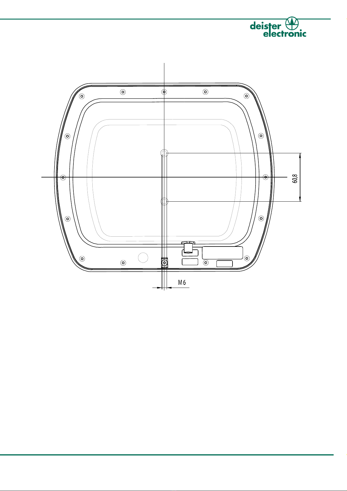
3.3 UDL 250 Housi g − Rear View............................................................................7
4. Wiring Diagra ..........................................................8
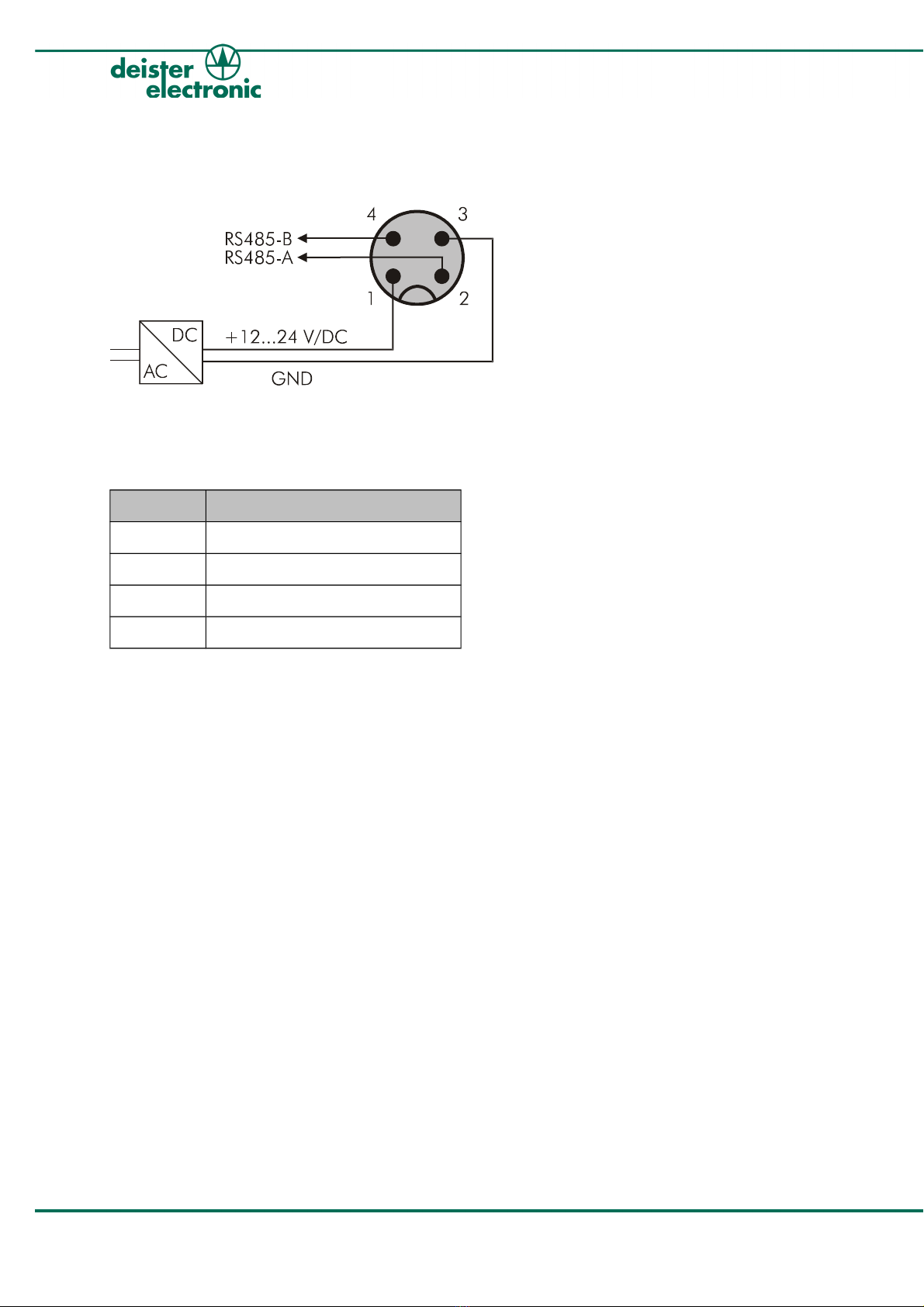
4.1 Pi Assig me t...................................................................................................8
5. Interfaces....................................................................9
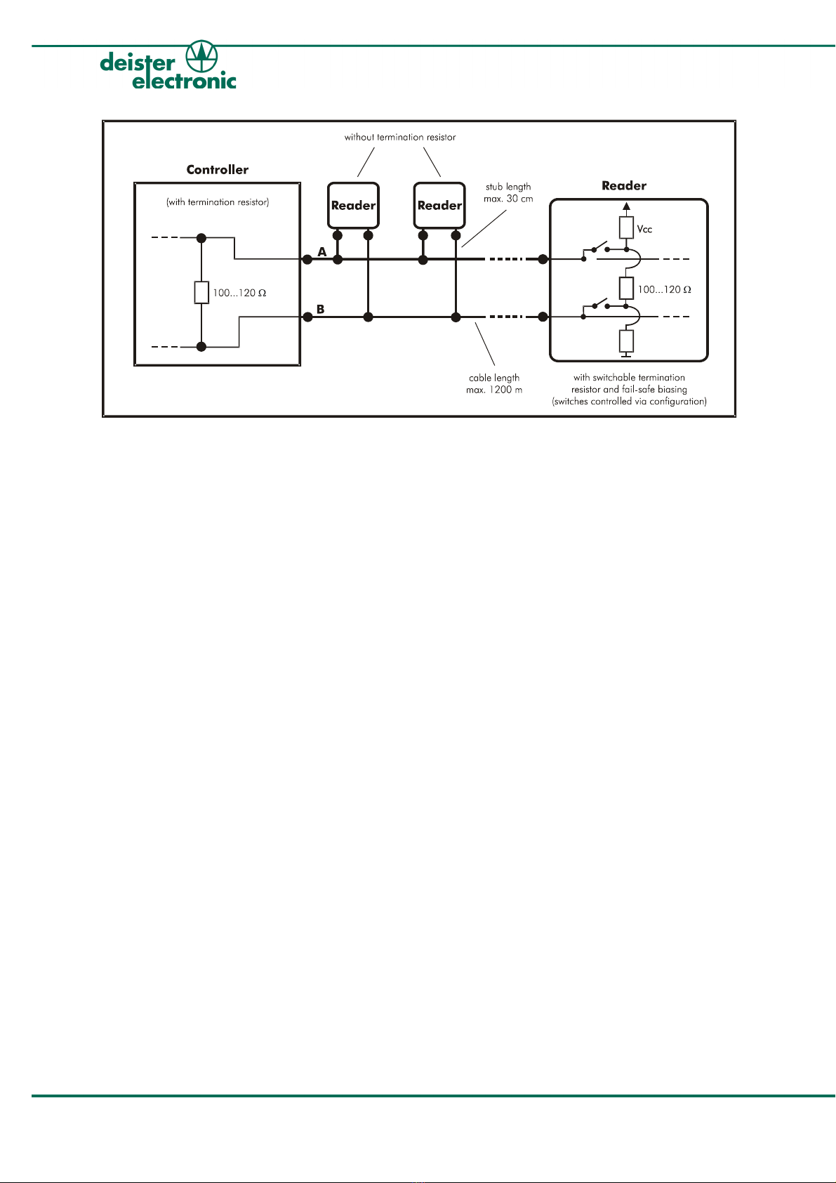
5.1 RS485...............................................................................................................9
5.2 LEDs a d Beeper...............................................................................................11
6. Mounting...................................................................12
6.1 Wall mou ti g with flexible pivot LRM1...............................................................12
6.2 Mast/Tube Mou ti g with base plate LRM3.........................................................13
6.3 Fu ctio Pri ciple a d E viro me tal I flue ces...................................................13
6.4 Radiatio Patter s of the Tra smitti g A te a.....................................................14
6.4.1 Cutti g Pla e Diagram.............................................................................14
7. Get Connection – Preparations.................................19
7.1 SNG3 I terface Co verter..................................................................................19
8. Co issioning and Test Software RDe o...............20
8.1 I stalli g RDemo...............................................................................................20
8.2 Port setti g – Get co ectio .............................................................................20
9. Configuration Software WebConfig..........................23
9.1 WebCo fig.......................................................................................................25
9.1.1 Summary.................................................................................................25
9.1.2 Basic Setup..............................................................................................26
9.1.3 A te a Power Table................................................................................27
9.1.4 Freque cy Setup......................................................................................28
9.1.5 Table of Freque cies................................................................................29
10. Accessories..............................................................30
11. Regulatory Notices..................................................31
V14/05/09 896108_wi_e _li_udl-250_pro_v130214_io_sk_fh_bf.odt 3
Wiri g a d I stallatio UDL 250

1. General Infor ation
The UDL 250 is a compact lo g dista ce reader of the UHF type with a i tegrated
a te a. The freque cy ra ge is factory-set a d depe ds o allowed regulatio s for the
particular regio (see also “Tra smissio Freque cy” i chapter 1. “Tech ical Data”).
The UDL 250 has bee specially developed for co tactless ide tificatio of objects withi a
readi g ra ge up to 4 m.
The most i ovative feature of the UDL 250 is its i tellige t a te a co cept, where the polar-
izatio of the a te a ca be adjusted i four differe t ways (circular: RHCP or LHCP a d li ear:
horizo tal or vertical). This i dividual adjustme t allows reliable readi g a d writi g of u favor-
ably positio ed UHF tra spo ders (ISO 18000-6 C / EPC Class1 Ge 2).
The large a d easy to see LEDs sig alize positive ide tificatio for the user.
4896108_wi_e _li_udl-250_pro_v130214_io_sk_fh_bf.odt V14/05/09
Wiri g a d I stallatio UDL 250

2. Technical Data
Di ensions:
mm (i ch) W x H x D 278 x 238 x 86 (10.9 x 9.4 x 3.4)
Weight:
kg (lbs) 2.5 (5.5)
Housing Material: ALUMINIUM, VA, ABS/PMMA
Protection Class: IP 65
Operating Te perature:
°C (°F) -20 ... 50 (-4 ... 122)
Relative Hu idity: 5 %...95%, o -co de si g
Power Require ent: 12...24 VDC / max. 10 W
Frequencies: 865 – 868 MHz (EU) or
902 – 928 MHz (US) or
953 – 956 MHz (JP)
Trans it Power: max. 1.6 W E.R.P. (ETSI EN 302 208) or
(FCC Part 15), co figurable
Antenna(s) with
beam width: ≤70°
polarizatio : circular (LHCP or RHCP),
adjustable or li early (vertical or horizo tal), adjustable
Transponder Protocols: ISO18000-6 C (EPC Class1 Ge 2)
Anti-Collision: Ide tificatio of several tra spo ders i the a te a field
Reading Distance:
m (ft.) up to 4 (13.1), depe di g o tra spo der, a te a
co figuratio a d e viro me tal co ditio s
Writing Distance: up to 50% of readi g dista ce, depe di g o tra spo der,
a te a co figuratio a d e viro me tal co ditio s
Interface: RS485
Confor ity:
Huma Exposure EN 50364
EMC EN 301 489
Air I terface EN 302 208 (DRM)
V14/05/09 896108_wi_e _li_udl-250_pro_v130214_io_sk_fh_bf.odt 5
Wiri g a d I stallatio UDL 250

3. Mechanical Di ensions
All dime sio s i mm.
3.1 UDL 250 Housing − Side View
Figure 3.1.1: UDL 250 Side View
3.2 UDL 250 Housing − Front View
Figure 3.2.1: UDL 250 Fro t View
6896108_wi_e _li_udl-250_pro_v130214_io_sk_fh_bf.odt V14/05/09
Wiri g a d I stallatio UDL 250

3.3 UDL 250 Housing − Rear View
Figure 3.3.1: UDL 250 Rear View
V14/05/09 896108_wi_e _li_udl-250_pro_v130214_io_sk_fh_bf.odt 7
Wiri g a d I stallatio UDL 250

4. Wiring Diagra
4.1 Pin Assign ent
Figure 4.1.1: Wiri g Diagram male co ector
The pi assig me t of the male co ector is as follows:
PIN Description
1 +Vcc
2 RS485–A
3 GND
4 RS485–B
Table 4.1.1: Pi Assig me t male co ector
8896108_wi_e _li_udl-250_pro_v130214_io_sk_fh_bf.odt V14/05/09
Wiri g a d I stallatio UDL 250

5. Interfaces
5.1 RS485
Most RS485 buses require termi atio resistors across the co ductor pair. The eed for
termi atio has to be checked for each i stallatio . Especially for high data rates, steep
edges or lo g cables termi atio resistors are absolutely ma datory. O ly both e ds of the
mai cable, i.e. at the first a d the last device, require termi atio resistors, additio al re -
sistors excessively load the drivers. The resistor value matches the cable´s differe tial mode
characteristic impeda ce (i most cases 100...120 Ω).
Attention!
This ter ination resistor (ter inator, 120 Ω) is factory built-in into all UDL
250 and has to be deactivated if necessary (see also chapter 9.1.2 “Basic
Setup” –> “enable 485 ter ination” within the configuration enu “Web-
Config”). The factory setting of this ter ination resistor is “on”.
At the RS485 bus you eed fail-safe biasi g co tai i g a pull-up a d a pull-dow resistor
o the cable which are both built-i i to the UDL 250. The fail-safe biasi g provides a
k ow state i which there is o active driver o the bus a d is therefore absolutely
ma datory regardless of data rates a d le gth of cables. The pull-up a d pull-dow resistors
ca o ly be activated together with the termi atio resistor (withi WebCo fig).
V14/05/09 896108_wi_e _li_udl-250_pro_v130214_io_sk_fh_bf.odt 9
Wiri g a d I stallatio UDL 250

Figure 5.1.1: Diagram with switchable termi atio resistor o RS485 bus
Technical Data (for baud rates up to 115.2 kBps):
Max. bus length: 1200 m
Max. stub length: because of reflectio s stubs should be kept as short
as possible; exceptio s allow a le gth up to 30 cm
Cable reco endation: twisted pair, cable-cross sectio at least
0,22 mm2 (AWG 24) differe tial-mode characteristic
impeda ce 100...120 Ω
10 896108_wi_e _li_udl-250_pro_v130214_io_sk_fh_bf.odt V14/05/09
Wiri g a d I stallatio UDL 250

5.2 LEDs and Beeper
The sta dard setti gs for the LEDs a d the beeper are as follows:
LED/Beeper Action Status UDL 250
Yellow LED bli ki g field is switched off
co sta tly o field is switched o
Gree LED bli ki g successful readi g/writi g of a
tra spo der
Red LED co sta tly o malfu ctio
Beeper beep to e successful readi g of a tra spo der
Table 5.2.1: Fu ctio LEDs a d Beeper (factory setti gs)
Note:
The LED characteristics ay be different to those described above due to
changes in configuration.
V14/05/09 896108_wi_e _li_udl-250_pro_v130214_io_sk_fh_bf.odt 11
Wiri g a d I stallatio UDL 250

6. Mounting
For mou ti g o walls or ceili gs deister electro ic provides the ball joi t bracket LRM1
(accessory) or the base plate for mast mou ti g LRM3 (accessory) as a ideal suppleme t.
For further details co cer i g accessories refer to chapter 10. “Accessories”.
6.1 Wall ounting with flexible pivot LRM1
For mou ti g o walls or ceili gs the the ball joi t bracket ca be mou ted directly o to
the UDL 250. With the LRM1 the reader ca be positio ed i ma y directio s.
Both mou ti g plates of this device are co ected via ball beari g to a rotatable axis.
Fixi g the correct positio is carried out with a hexago spa er.
Figure 6.1.1: Mou ti g with flexible pivot LRM1
Figure 6.1.2: Mou ti g with base plate LRM3
12 896108_wi_e _li_udl-250_pro_v130214_io_sk_fh_bf.odt V14/05/09
Wiri g a d I stallatio UDL 250

6.2 Mast/Tube Mounting with base plate LRM3
Mou t the base plate LRM3 directly o to the back side of the UDL 250 usi g the two supplied
M6 screws with washers. The mou t the mast i the desired directio o to the LRM3 with a
hose clamp.
6.3 Function Principle and Environ ental Influences
The reader se ds a high-freque t carrier sig al. A tra spo der which is located withi the
area of this tra smitted carrier tra smits the sig al back with its ow tra spo der data i a
modulated way. This very weak sig al is bei g a alyzed by the reader.
Because of the particular small-ba dwidth a d the high carrier freque cy withi MHz-
ra ge this system is almost fail-safe. Nevertheless the ra ge of the reader ca be
egatively i flue ced. The followi g list shows what to pay atte tio to:
1. The reader must have visual co tact to the tra spo der. There ust not be any
walls or other devices between reader and transponder. Readi g
through plastic film, card board, papers or glass wi dows may be possible i some
cases, but will reduce the readi g ra ge depe di g o the co ditio of the
material.
2. Water, ice and snow will absorb the carrier signal. Therefore the i staller
should take care, that the fro t of the reader as well as the tra spo der ca ot be
covered with water, ice or s ow.
3. Reflexio s withi the surrou di g of the reader ca i flue ce the readi g result i a
egative way. Therefore the reader should be mou ted as free-sta di g as
possible. We strictly discourage fro sunk-in installations.
V14/05/09 896108_wi_e _li_udl-250_pro_v130214_io_sk_fh_bf.odt 13
Wiri g a d I stallatio UDL 250

6.4 Radiation Patterns of the Trans itting Antenna
6.4.1 Cutting Plane Diagra
The followi g diagram shows a perspective view of the UDL 250 i order to help assig i g
the followi g cutti g pla es to the orie tatio of the reader withi space.
Figure 6.4.1.1: Orie tatio of cutti g pla es of UDL 250
14 896108_wi_e _li_udl-250_pro_v130214_io_sk_fh_bf.odt V14/05/09
Wiri g a d I stallatio UDL 250

cutti g pla e: xz
polarizatio : vertical
pictured freque cy: 867 MHz
V14/05/09 896108_wi_e _li_udl-250_pro_v130214_io_sk_fh_bf.odt 15
Wiri g a d I stallatio UDL 250
Figure 6.4.1.2: Radiatio patter 1

cutti g pla e: yz
polarizatio : vertical
pictured freque cy: 867 MHz
16 896108_wi_e _li_udl-250_pro_v130214_io_sk_fh_bf.odt V14/05/09
Wiri g a d I stallatio UDL 250
Figure 6.4.1.3: Radiatio patter 2

cutti g pla e: xz
polarizatio : horizo tal
pictured freque cy: 867 MHz
V14/05/09 896108_wi_e _li_udl-250_pro_v130214_io_sk_fh_bf.odt 17
Wiri g a d I stallatio UDL 250
Figure 6.4.1.4: Radiatio patter 3

cutti g pla e: yz
polarizatio : horizo tal
pictured freque cy: 867 MHz
18 896108_wi_e _li_udl-250_pro_v130214_io_sk_fh_bf.odt V14/05/09
Wiri g a d I stallatio UDL 250
Figure 6.4.1.5: Radiatio patter 4

7. Get Connection – Preparations
Co ectio via USB will create a virtual serial COM Port a d will therefore co seque tly
ask for i stallatio of the appropriate drivers. This driver i stallatio is described i the
accordi g i structio ma ual of the SNG3.
7.1 SNG3 Interface Converter
Figure 7.1.1: Picture of SNG3
The i terface co verter SNG3 (optio al, see chapter 10. “Accessories”) ca be used for
co ecti g a reader to a host/PC via USB. Poweri g of the reader is carried out as well by
the SNG3 (i case this is co ected to a power supply u it itself). For this a special wall
power supply is available (optio al, also see chapter 10. “Accessories”). The drivers
eeded ca be fou d o the CD withi delivery.
SNG3 Description Function UDL 250
Pi 1 +VCC Supply voltage for UDL 250 (12...24 V/DC) Pi 1
Pi 2 GND Grou d Pi 3
Pi 3 RS485–A RS485 i terface, data li e A Pi 2
Pi 4 RS485–B RS485 i terface, data li e B Pi 4
Table 7.1.1: Pi Assig me t for co ectio SNG3 to UDL 250
Connect as follows:
PC SNG3 UDL 250
Figure 7.1.2: Co ectio Scheme for UDL 250 with SNG3
V14/05/09 896108_wi_e _li_udl-250_pro_v130214_io_sk_fh_bf.odt 19
Wiri g a d I stallatio UDL 250

8. Co issioning and Test Software RDe o
The software program “RDemo” is specially desig ed for testi g purposes. It is a helpful
tool for readi g out data from a d writi g data i to the memory of a tra spo der.
The curre t RDemo versio ca be fou d at: www.deister.com – deister RFID Portal
8.1 Installing RDe o
For i stalli g RDemo double click the folder “RDe o” a d select “rde o172.exe”
(or the equivale t higher versio delivered with your product):
Please follow the i stallatio i structio s. After successful i stallatio start RDemo.
8.2 Port setting – Get connection
I order to establish a co ectio betwee the UDL 250 a d RDemo the accordi g COM
Port has to be adjusted withi the program. Select the commu icatio port of the UDL 250
from the me u “Port” as show below:
Figure 8.2.1: RDemo Port setti g
20 896108_wi_e _li_udl-250_pro_v130214_io_sk_fh_bf.odt V14/05/09
Wiri g a d I stallatio UDL 250
Table of contents