Deka DURATION DD5300 User manual

DEKA DURATION DD5300
1
Installation and User Manual
DD5300 Energy Storage System
LOW VOLTAGE & HIGH VOLTAGE

DEKA DURATION DD5300
2
ATTENTION: The battery could explode and/or be severely damaged if dropped or
crushed.
ATTENTION: Appropriate mechanical lifting equipment must be used since
the Battery Module weighs 126.3 lb (57.3 kg).
ATTENTION: The battery may explode if exposed to open flames or other
extreme sources of heat.
ATTENTION: The battery terminals must be disconnected before
commencing any work on the battery.
ATTENTION: This battery can accumulate parasite current. Do not touch
the B+ and B- terminals. Always check the B+ and B- terminals with a
voltmeter.
Always ensure that there are ZERO volts present on the terminals before
performing any operation on the battery.
ATTENTION: Always wear Individual protection devices, use insulated tools,
and follow the safety plan of this manual.
At end of life, these batteries must be disposed of properly by a
certified professional company.

DEKA DURATION DD5300
3
Contents
Statement:....................................................................................................................................... 6
Preface: ........................................................................................................................................... 6
Declaration: ..................................................................................................................................... 6
System Design
.............................................................................................................................. 7
Battery Operation ............................................................................................................................ 7
Storage ............................................................................................................................................................ 7
Temperature .................................................................................................................................................... 7
Depth of Discharge (DoD).................................................................................................................................. 7
Charging........................................................................................................................................................... 7
Warranty.......................................................................................................................................................... 7
Product Overview ............................................................................................................................ 8
Symbols Used................................................................................................................................... 8
Battery Module Overview ................................................................................................................ 9
Safety Warnings and Notifications...................................................................................................11
Warning Statements .......................................................................................................................12
General Preparation........................................................................................................................13
SECTION 1 - STORAGE & PRE-OPERATIONAL PROCEDURES...............................................................16
1.1 Storage - Transportation –Removing / Relocation of Batteries ................................................................... 16
1.2 Module Unpacking and Handling ............................................................................................................... 18
1.2.1 Package Information and System Configuration List .........................................................................................................19
1.3 Wall Mount or Stack Mount Configuration ................................................................................................. 19
1.3.1 Battery Dimensions* (Wall Bracket) ................................................................................................................................19
1.3.2 Wall Mount .....................................................................................................................................................................19

DEKA DURATION DD5300
4
1.3.3 Stack Mount....................................................................................................................................................................23
1.4 Battery Terminal Function Definition.......................................................................................................... 25
1.5 Out of the Box Pre-Operational Check........................................................................................................ 26
SECTION 2 - LOW VOLTAGE CONFIGURATION....................................................................................27
2.1 Product Introduction................................................................................................................................. 27
2.1.1 Identifying the Individual Module....................................................................................................................................27
2.1.2 Accessory List (Standard Kit 120A Single Module LV)........................................................................................................29
2.1.3 Necessary Installation Tools.............................................................................................................................................30
2.1.4 Personal Protective Equipment +1000 Vdc Insulated Tools..............................................................................................30
2.2 Low Voltage Module Wiring and Set Up...................................................................................................... 31
2.2.1 Battery Connection Terminals .........................................................................................................................................31
2.2.2 BATTERY CAN Pin Out .....................................................................................................................................................31
2.3 Low Voltage DIP Switch Settings................................................................................................................ 32
2.3.1 LOW VOLTAGE PARALLEL CONFIGURATION.....................................................................................................................33
2.3.2 LED Visual Indication Lights.............................................................................................................................................33
2.4 Module Activation and Shutdown.............................................................................................................. 33
2.5 Low Voltage Parallel Set Up Overview........................................................................................................ 35
2.5.1 Auto ID Assignment and DIP Configuration for LOW Voltage Single Cluster (Parallel Connection) ...................................36
2.5.2 Single Cluster DIP and DATA Connection .........................................................................................................................38
2.5.3 Parallel Battery Wiring Connections ................................................................................................................................39
2.5.4 Low Voltage Single Stack Power and Data Connections (15-Modules Maximum).............................................................40
2.5.5 LED Bar Indications..........................................................................................................................................................42
2.6 Stand Alone Battery Front Panel Control .................................................................................................... 43
2.6.1 Start Battery....................................................................................................................................................................43
2.6.2 Shut Down Battery..........................................................................................................................................................43
2.6.3 Low Battery –Force Charge.............................................................................................................................................43
2.7 Parallel Battery Configuration.................................................................................................................... 43
2.7.1 Activation of Parallel Batteries (From Master to last module for a maximum of 15) ........................................................43
2.7.2 Shutdown of Parallel Batteries........................................................................................................................................44
2.7.3 LV Direct Parallel Connection WITHOUT Certified Inverter BMS Communication (Open-Loop) ........................................45
2.7.4 LV Direct Parallel Connection WITH Certified Inverter BMS Communication (Closed-Loop) .............................................46
2.8 Power Connection of a Single Cluster......................................................................................................... 47
2.9 CAN HUB for Multi Cluster Configuration ................................................................................................... 49
2.9.1 Low Voltage CAN HUB Dimensions..................................................................................................................................51
2.9.2 Control Logic and Protection Limit...................................................................................................................................51
2.9.3 CAN Hub General System Description ..............................................................................................................................52
2.9.4 Multi Cluster Configurations............................................................................................................................................53
2.9.5 Master ID Set Up and Connection Diagram......................................................................................................................54
2.9.6 Power Connection Example.............................................................................................................................................55
2.9.7 Conceptual Diagram of a Cluster composed by 5 clusters and 8 batteries each................................................................56

DEKA DURATION DD5300
5
2.9.8 Conceptual Diagram between Master Modules of multiple clusters.....................................................................................57
2.10 Cluster Configuration Accessories ............................................................................................................ 58
2.10.1 Single Cluster Configuration Kit .......................................................................................................................................58
2.10.2 Multi Cluster Hub Device.................................................................................................................................................58
2.11 Low Voltage Inverter Compatibility List................................................................................................... 59
SECTION 3 - HIGH VOLTAGE CONFIGURATION ...................................................................................61
3.1 Product Introduction................................................................................................................................. 62
3.1.1 Identifying the Individual Battery Module .......................................................................................................................62
3.1.2 Product Identification and labels.....................................................................................................................................63
3.1.3 HV BOX Dimensions ........................................................................................................................................................64
3.1.4 Battery Module Accessory List (Standard Kit) ..................................................................................................................65
3.1.5 HV BOX KIT (Included in the carton box)..........................................................................................................................66
3.1.6 Necessary Installation Tools.............................................................................................................................................67
3.1.7 Personal Protective Equipment + 1000 Vdc Insulated Tool Kit .........................................................................................67
3.2 High Voltage Battery Module Wiring and Set Up.......................................................................................... 68
3.2.1 Battery Connections........................................................................................................................................................68
3.3 HV BOX Overview ..................................................................................................................................... 70
3.4 High Voltage Module Configuration............................................................................................................ 72
3.5 High Voltage DIP Switch Settings................................................................................................................ 73
3.5.1 Serial Tower Connection #1 Set-Up of the HV Box CAN Communication Loop...................................................................74
3.6 Serial Battery Wiring Connections.............................................................................................................. 75
3.6.1 High Voltage Power Connections .....................................................................................................................................76
3.6.2 DATA Connections (Example of 12-Modules)...................................................................................................................77
3.6.3 HV Box and Battery Module Power Connection..............................................................................................................79
3.6.4 Single HV Box Connection to an Inverter ........................................................................................................................80
3.6.5 Multi HV Box Connection ................................................................................................................................................81
3.6.6 Multi HV Box Connection ................................................................................................................................................82
3.7 HV Box ADDRESS....................................................................................................................................... 83
3.7.1 LED Visual Indication Lights ............................................................................................................................................85
3.7.2 Stand-Alone Battery Front Panel Control * FORCED CHARGE*.........................................................................................85
3.8 HIGH VOLTAGE INVERTER COMPATIBILITY ................................................................................................. 87
3.9 WECO BMS - LOW VOLTAGE PC SOFTWARE for DD5300 ............................................................................. 88
3.10 WECO BMS - HIGH VOLTAGE PC SOFTWARE for DD5300 ........................................................................... 92

DEKA DURATION DD5300
6
Statement:
The information and guidance contained in this manual is related to the DEKA DD5300 Stackable model
of battery. This manual contains two sections:
Section 2 is for LOW VOLTAGE APPLICATION
Section 3 is for HIGH VOLTAGE APPLICATION
In case of product upgrades or other reasons, this document will be adjusted accordingly. Unless otherwise
agreed, this document is intended to be used only as a guide, and all statements, information and advice in the
documentation shall not constitute any express or implied action in contradiction to local regulations or
standards.
For more information, please contact us.
The official information and the latest data sheet are available on www.mkbattery.com
It is essential that the Battery Module is equipped with the latest firmware version available.
New batteries always ship with the latest version of firmware.
From time to time, firmware will be updated to improve the functionalities and battery capabilities. The
latest version of the firmware is always available free of charge and can be updated by your local installer. You
can always contact durationsupport@dekabatteries.com for additional information on the upgrade
procedure.
Preface:
Thank you for choosing our product. We will provide you with a high-quality product as well as reliable
after-sale service. To protect against harm to both personnel and the product, please read this manual
carefully.
This manual provides detailed information on operation, maintenance and troubleshooting of the product as
well as health and safety advice.
Declaration:
The manufacturer holds the right of final explanation of any content in this manual.
All trademarks shown in this manual belong to their legitimate owners; trademarks of third parties,
product names, trade names, corporate names and companies mentioned may be trademarks owned by
their respective owners or registered trademarks of other companies and are used purely for explanatory
purposes and for the benefit of the owner, without any purpose of violation of the copyright in force.
NOTICE:
This Battery Module is designed to be used indoors.
The STANDARD IP20 degree of protection does not allow installation in outdoor environments even if sheltered
from the weather.
The Battery Modules must be stored indoors in a clean, dry, cool location in a limited access area.

DEKA DURATION DD5300
7
System Design
System Design is the process of defining the architecture, components, modules, interfaces and load data for a
system to satisfy specified requirements.
For a solar energy system, these components are the PV modules, inverter/charge controller & batteries, as
well as the different interfaces of those components.
Battery Operation
There are several factors that affect the operation of the battery that could impact its ability to deliver capacity
and life expectancy.
Storage
Battery Module shall be stored in original packaging, in a clean, level, dry, cool location indoors.
Recommended storage temperature is 77°F (25°C).
The battery can be stored in the range of -4°F to +113°F (-20°C to +45°C) but it requires an inspection* and
recharge** every three months (max charging current is 0.1C).
Max SoC storage % is 50%.
*Inspection parameters –identify the State of Charge (SOC), look for any alarms and address accordingly, look for physical
damage to the Battery Module. **Charge at 0.1C and not more than 50% SOC. If shipped by sea, you must refer to the
UN38.3 standard, if by road, refer to the local codes.
Temperature
Many chemical reactions are affected by temperature, and this is true of the reaction that occurs in a storage
battery.
The chemical reaction of a Li-Ion is slowed down by a lowering of the electrolyte temperature that results in
less capacity.
A battery that will deliver 100% of rated capacity at 77°F (25°C) will only deliver approximately 75% of rated
capacity at +50°F (+10°C).
At temperatures down to +19.4°F (-7°C) the charge current may be limited to 0.1C depending on other factors,
however at temperatures below +19.4°F (-7°C) charging is restricted by the BMS.
As part of the Performance Warranty, Charge and Discharge shall be in the range +68°F to +77°F (+20°C to
+25°C). Any usage outside this range is not covered by Performance Warranty.
Depth of Discharge (DoD)
Depth of discharge is a function of design. The deeper the discharge per cycle, the shorter the life of the
battery. A cycle is a discharge and its subsequent recharge regardless of depth of discharge.
Charging
The majority of battery capacity/life issues can be traced to improper charging. Improper charging settings may
lead to an overcharging or undercharging condition.
Warranty
Although the BMS of the battery allows a wide range of use, both in terms of temperature and charging
currents, this should not be construed as an implicit authorization to use the battery at these levels.
For the purposes of the Performance Warranty, it is mandatory that the battery is used within the range of
temperature and charge/discharge current, and Depth of Discharge indicated in the Performance Warranty.
Warranties only apply to batteries connected via BMS line to an approved inverter.
Any other use, even if permitted by the BMS ranges, is not covered by the Performance Warranty.

DEKA DURATION DD5300
8
Product Overview
The Deka Duration DD5300 is a Stackable Battery Module with a DUAL VOLTAGE module that can be used in a Low
Voltage configuration or in a High Voltage configuration.
For LOW VOLTAGE (48.5-58.4 Vdc)* Configuration Refer to Section 2
For HIGH VOLTAGE (200-934.4 Vdc)* Configuration Refer to Section 3
*Voltage ranges are estimates only as they always depend on interactions with other devices and ambient conditions.
Information in this Manual
About this Manual
This manual relates only to the DD5300 Stackable Battery Module. Only trained and authorized personnel should install,
repair or charge these Battery Modules. This manual should be reviewed in its entirety for proper storage, installation and
operation of the Battery Module.
Use Range
This installation guidance applies for the High Voltage and Low Voltage Inverters.
Make sure to use the correct inverter charging parameters before connecting to the battery.
Each Deka Duration DD5300 Battery Module has two different circuits and depending on the inverter voltage range, the
installer must choose the correct battery configuration for that range.
Additional Information
Product specifications subject to change without notice.
IMPORTANT NOTICES:
HV BOX minimum startup voltage is 150 Vdc, (three modules) however it is suggested to use a minimum of four modules
to have an adequate buffer of energy to prevent low voltage shutdown of the HV BOX during a long period of the
inverter on standby, or due to solar charger inactivity.
The Deka Duration DD5300 Stackable Battery Module is designed for home and commercial applications from 5.3 kWh to
556.5 kWh in Low Voltage configuration and from 21.2 kWh to 763.2 kWh in High Voltage configuration.
For the calculation of the energy of a cluster (in both LV and HV systems) the nominal capacity of a battery is generally
counted in 5.3kWh as a result of the multiple connection inefficiency, estimated at a loss of 2%.
Symbols Used
Symbol Meanings:
CAUTION:
CAUTION represents hazardous situations which can cause injuries if not avoided.
NOTICE:
NOTICE represents the situations which can cause damage to property if not avoided.
INFORMATION:
INFORMATION provides tips that are valuable for optimum installation and operation of the product.

DEKA DURATION DD5300
9
Battery Module Overview
INFORMATION provides tips that are valuable for optimum installation and operation of the product.
CONNECTION HUB
PROTECTION PLATE
UPPER REMOVABLE
BRACKET
WALL BRACKET
LOWER REMOVABLE
BRACKET
REMOVABLE
HANDLES
STRUCTURAL FEET
RUN BUTTON
POWER
SWITCH
OPERATOR PORT
DEKA DURATION DD5300
10
ATTENTION:
THE BATTERY IS DUAL VOLTAGE –
IT CAN BE INSTALLED IN EITHER A HIGH VOLTAGE CONFIGURATION OR A LOW VOLTAGE CONFIGURATION,
BUT NEVER BOTH AT THE SAME TIME.
BE AWARE OF THE DIFFERENT CONNECTION METHODS AND THE SPECIFIC USE OF THE TERMINAL
CONNECTORS.
LOW VOLTAGE ONLY
SCREW TERMINAL
HIGH VOLTAGE ONLY
FAST CONNECTORS
-
HIGH VOLTAGE
SERIAL CONNECTION
CONNECTION
LOW VOLTAGE
PARALLEL CONNECTION

DEKA DURATION DD5300
11
Safety Warnings and Notifications
Installation environment requirements: The Deka Duration DD5300 Stackable Battery Module is designed for
household/commercial purposes. For installation, it must be installed in a location complying with IP20 (IP 55 or 65 are
available on request). Installations in locations that do not comply with IP20 may cause failure and/or damage to the
product, in which case the product warranty will become void.
Safety Guidelines
CAUTION:
Adequately insulated tools (as defined by ASTM F1505 “Standard Specification for Insulated and Insulating Hand Tools”
shall be used at all times to ensure battery terminals are not short circuited. All electrical connections on the Deka
Duration DD5300 Battery Module shall be made only by qualified personnel.
When installed and operated in accordance with this manual, the Deka Duration DD5300 Battery Module will perform in a
safe and reliable manner in accordance with the battery operating specifications.
Subjecting the battery to an unsuitable operating environment or to damage, misuse or abuse may result in health and
safety risks such as overheating or electrolyte smoke potential. All personnel must comply with the safety precautions and
observe all warnings as detailed in this document. If any of the safety precautions or procedures detailed in this manual
are not fully understood by the reader, the reader must not perform any operation on the battery until they have
contacted the DEKA DURATION technical service representative for clarification and confirmation of understanding of the
correct procedure.
The safety guidelines included in this document may not include or consider all the regulations in your area of
installation/operation. When installing and operating this product, the installer must review and consider applicable
Federal, State and Local laws and regulations in accordance with the industry standards of the product.
Installation personnel shall not wear metallic objects, such as watches, jewelry and other metal items when performing
installations. Do not store un-insulated tools in pockets or tool belt while working in vicinity of battery to avoid short
circuits and personal injuries.
CAUTION:
The weight of an individual Deka Duration DD5300 Battery Module is 126.3 lb (57.3 kg). Please use original packaging and
follow all safety precautions if the Battery Module is to be relocated to another location, to avoid damage to the product
and personal injury.
ATTENTION:
The high voltage configuration must have a minimum number of 4 modules in order to reach at least 200 Vdc in series.
The maximum number of modules that can be stacked is 8 on each tower (due to the tower height and stability) and
the maximum number of modules composing an HV string must not exceed 16.

DEKA DURATION DD5300
12
Warning Statements
Lithium Iron Phosphate (LiFEP04) Battery or Cell DANGER
Hazard Statement
The materials contained in this product may only represent a hazard if the integrity of the cell or battery is compromised; physically,
thermally, or electrically abused. The below are the hazards anticipated under those conditions: Causes skin irritation. Causes serious eye
irritation. May cause an allergic skin reaction. Causes damage to organs (Bone, teeth) through prolonged or repeated exposure. Very toxic
to aquatic life. Harmful to aquatic life with long lasting effects.
Precautionary Statement
Prevention
Do not breathe dust. Do not eat, drink or smoke when using this product. Wear protective gloves/protective clothing/eye protection/face
protection. Wash thoroughly after handling. Contaminated work clothing must not be allowed out of the workplace. Avoid release to the
environment.
Response
If on skin: Wash with plenty of water. If skin irritation or rash occurs: Get medical advice/attention. Take off contaminated clothing and
wash it before reuse. If in eyes: Rinse cautiously with water for several minutes. Remove contact lenses, if present and easy to do.
Continue rinsing. If eye irritation persists: Get medical advice/attention. Get medical advice/attention if you feel unwell. Collect spillage.
Storage
Store as indicated in the Storage section of this manual.
Disposal
Dispose of contents/container in accordance with local/regional/national/international regulations.
Supplemental information
Under normal conditions of processing and use, exposure to the chemical constituents in this product is unlikely. The chemicals are
contained in a sealed steel housing. Risk of exposure occurs only if the battery is mechanically, thermally or electrically abused. If this
occurs, exposure to the electrolyte solution contained within can occur by inhalation, ingestion, eye contact and skin contact.
Additional Notes: CAUTION: Do not dispose in fire, mix with other battery types, charge above specified rate, connect improperly, or short
circuit, which may result in overheating, explosion or leakage of cell contents. Do not open or disassemble. Do not puncture, deform,
incinerate or heat above 85°C (185°F). Keep away from heat/sparks/open flames/hot surfaces. - No smoking.
This product is a "Hazardous Chemical" as defined by the OSHA Hazard Communication Standard, 29 CFR 1910.1200. Additional
information is given in the Safety Data Sheet.
Emergency Number USA/Canada: CHEMTREC (800) 424-9300, Outside USA 1 (703) 527-3887
WARNING: This product can expose you to chemicals including Carbon black, which is known to the State of
California to cause cancer, birth defects or other reproductive harm. For more information go to www.P65Warnings.ca.gov.

DEKA DURATION DD5300
13
General Preparation
Before Installation:
Ensure that all the modules are turned OFF.
Battery installation location should be at least 20m away from sources of heat, sparks or other sources of extreme
temperature. Battery connecting cables shall be as short as possible to prevent excessive voltage drops.
Batteries with different capacity, different type/model or design or from different manufacturers shall not be connected together.
1.
Before connecting the battery, the battery positive and negative poles shall be carefully
checked to ensure correct installation.
2.
The installation location must be on a flat level surface, in a dry, clean and protected room,
away from water and humidity.
The mechanical installation method for the Deka Duration DD5300 Battery Modules can be
considered “conceptually’’ the same for HV and LV configurations.
Before starting any operation on the battery, make sure to position the modules in their final position
and structurally fix all the modules that make up the system.
The installer who intends to install the Deka Duration DD5300 Battery Module in the HV
configuration should read this entire manual including the HV configuration information defined in
Section 3.

DEKA DURATION DD5300
14
ATTENTION:
STACKABLE INSTALLATION INFORMATION
The stack configuration shall be concluded by interlocking the modules by using the module feet as
shown below:
Install the feet across
the modules
Use the two screws to
fix the feet across the
modules
The screw holes are on
the side of the battery

DEKA DURATION DD5300
15
When operating in stack mode, remove the upper (trapezoidal) front part from the Battery Module to allow the cables to pass through.
The front plate must be reinstalled to protect the cables after the installation is complete.
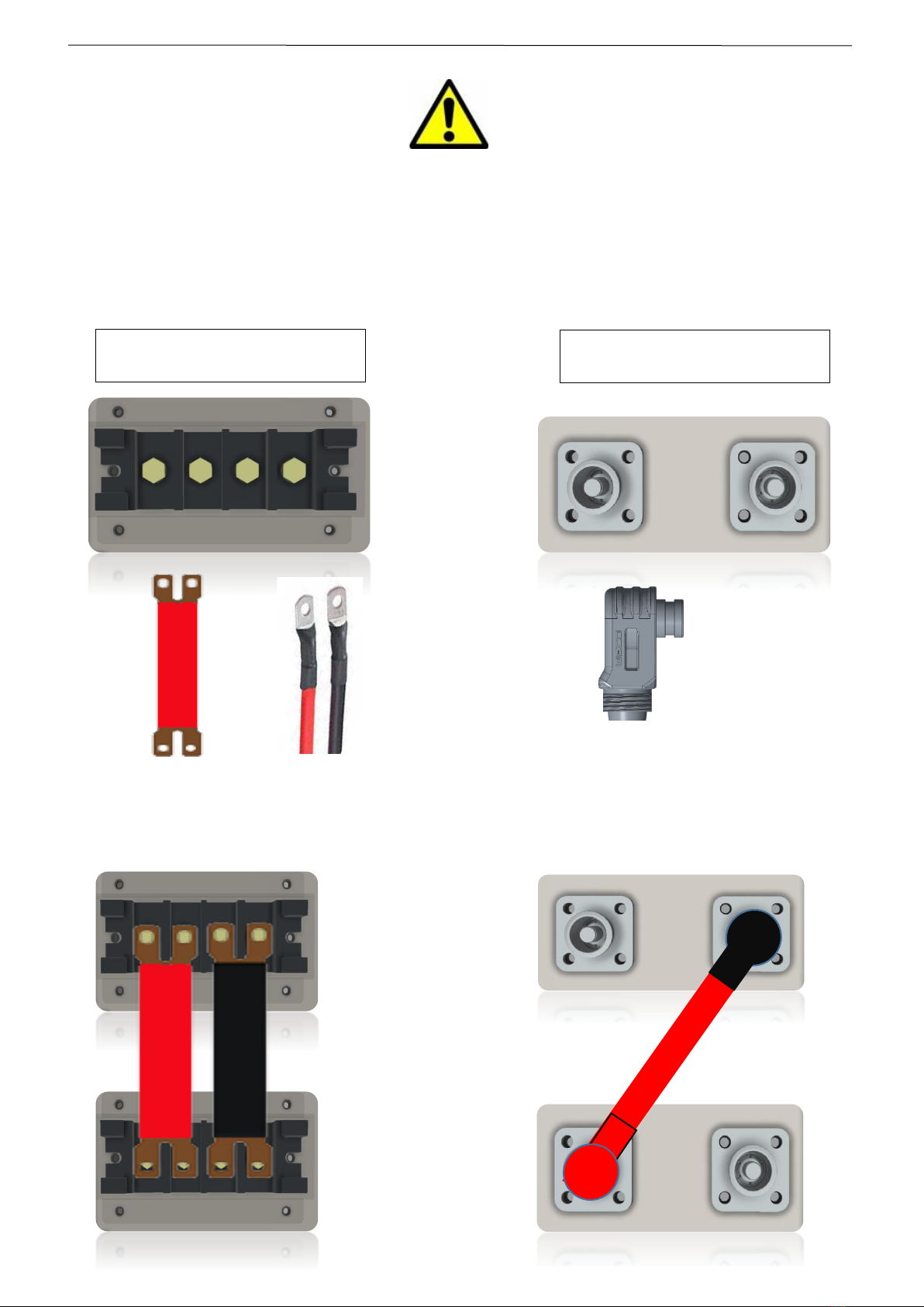
ATTENTION:
The DD5300 Battery Module has two terminals for connecting the power supply.
The installer must pay the utmost attention to the respective functions.
The low voltage screw terminal only supports parallel
connection with maximum voltage 60V
CAUTION> Connecting these terminals in series will
cause serious damage to the battery
DO NOT CONNECT IN SERIES
Fast Connector terminals only support series connections
up to 1000Vdc
CAUTION> Connecting these terminals in parallel will cause
serious damage to the battery
DO NOT CONNECT IN PARALLEL
REMOVE WHEN OPERATING IN
STACKABLE MODE
CABLES PASSAGE
LOW VOLTAGE
HIGH VOLTAGE

DEKA DURATION DD5300
16
SECTION 1 - STORAGE & PRE-OPERATIONAL PROCEDURES
1.1 Storage - Transportation –Removing / Relocation of Batteries
✓This Battery is considered DANGEROUS GOODS by the United Nations and must be treated accordingly.
✓Each box comes from the factory with the below labels:
✓This battery can only be transported and stored with the original approved carton box, Certified as
per UN CLASS 9 Y80.
✓This Battery must be stored in its original carton box in a dry and cool place. DEKA DURATION carton
box is marked as below:
✓The transportation and Storage State of Charge (SoC) shall not exceed 50%.
✓The shelf period without recharging is 6 months, and then requires a quick charge up to 50% DoD.
Charge at 0.1C and not more than 50% SOC. If shipped by sea, you must refer to the UN38.3
standard. If by road, refer to local codes.
✓To preserve the performance and shelf life, this battery should optimally be stored at 77°F (25°F)
and @70% humidity.
✓Acceptable storage temperature range of the battery is between +59°F and +95°F (+15°C and
+35°C).
✓The self-discharge in the range of +59°F to +119°F (+15°C to +35°C) is around 1% a month. Anything
outside this range could exceed 10% a month.
✓Do not store the batteries near sources of heat, vapor, gas, fuels, sparks or anything that could
generate fire or explosion.
✓Store inside and protect from water and moisture.
✓Transportation of new and used or damaged modules must be in accordance with the UN 38.3
Regulation and with the Federal, State and Local regulations.
✓If one or more working Battery Modules need to be removed or relocated, they must be marked as
USED BATTERY (follow local rules).
✓If one or more Battery Modules need to be replaced due to damage, they should be marked as
DAMAGED USED BATTERY and follow any applicable procedures and all Federal, State and Local
regulations.

DEKA DURATION DD5300
17
The installer approaching this battery model for the first time must understand the use and operation of
its accessories.
The DD5300 Battery Module can be equipped with an auxiliary combiner such as:
DD21001 HUB for Low Voltage configurations up to 105 batteries (7-Clusters x 15-Modules)
DD21002 HV BOX device for High Voltage configurations up to 144 batteries (9-Clusters x 16-Modules).
Each device or accessory of the DD5300 will have a specific Firmware that manages the logic and
interconnection functions between Battery Modules and devices.
It is therefore important to understand the operational and interaction concepts of the DD5300 battery within a
more complex system.
DD21002 HV BOX
DD21001 HUB
LOW VOLTAGE
HIGH VOLTAGE
Firmware
20.00
Firmware
30.00
DD21001 HUB
Firmware
50.00
HV BOX DD21002
DD5300 MODULE
DEKA DURATION DD5300
18
1.2 Module Unpacking and Handling
The battery is always delivered in WALL mode, and it is therefore necessary for the installer to make simple changes to
install the STACK kit. Below are the installation phases.
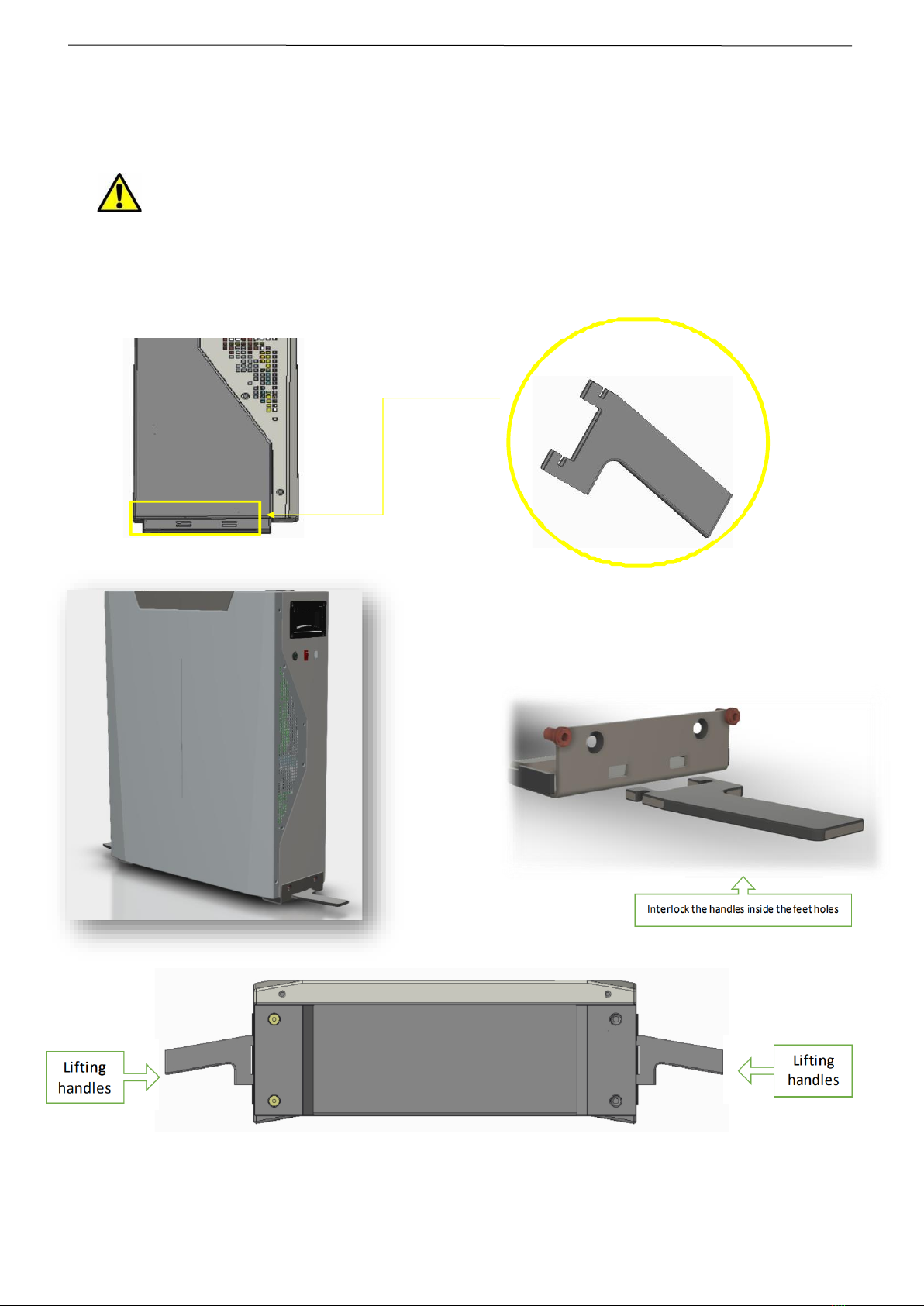
ATTENTION:
The battery must be lifted by four persons, using the four handles.
Two handles are built in and the other two are provided as temporary handles to be used as shown below.
Open the carton box, find the portable and retractable handles, position them and proceed with lifting.
DEKA DURATION DD5300
19
1.2.1 Package Information and System Configuration List
The battery box is packed in cartons with accessories.
Upon receipt, review the configuration list carefully to make sure that the battery box and accessories are received in the
correct quantities and type, and visually inspect to ensure that they are free from damage.
Refer to Section 2.1.3 for Low Voltage packing list and to Section 3.1.3 for High Voltage packing list.
If battery is damaged and/or components missing, contact your local Deka Duration representative.
1.3 Wall Mount or Stack Mount Configuration
NOTE: The Deka Duration DD5300 Battery Module ships as standard in the wall mount configuration.
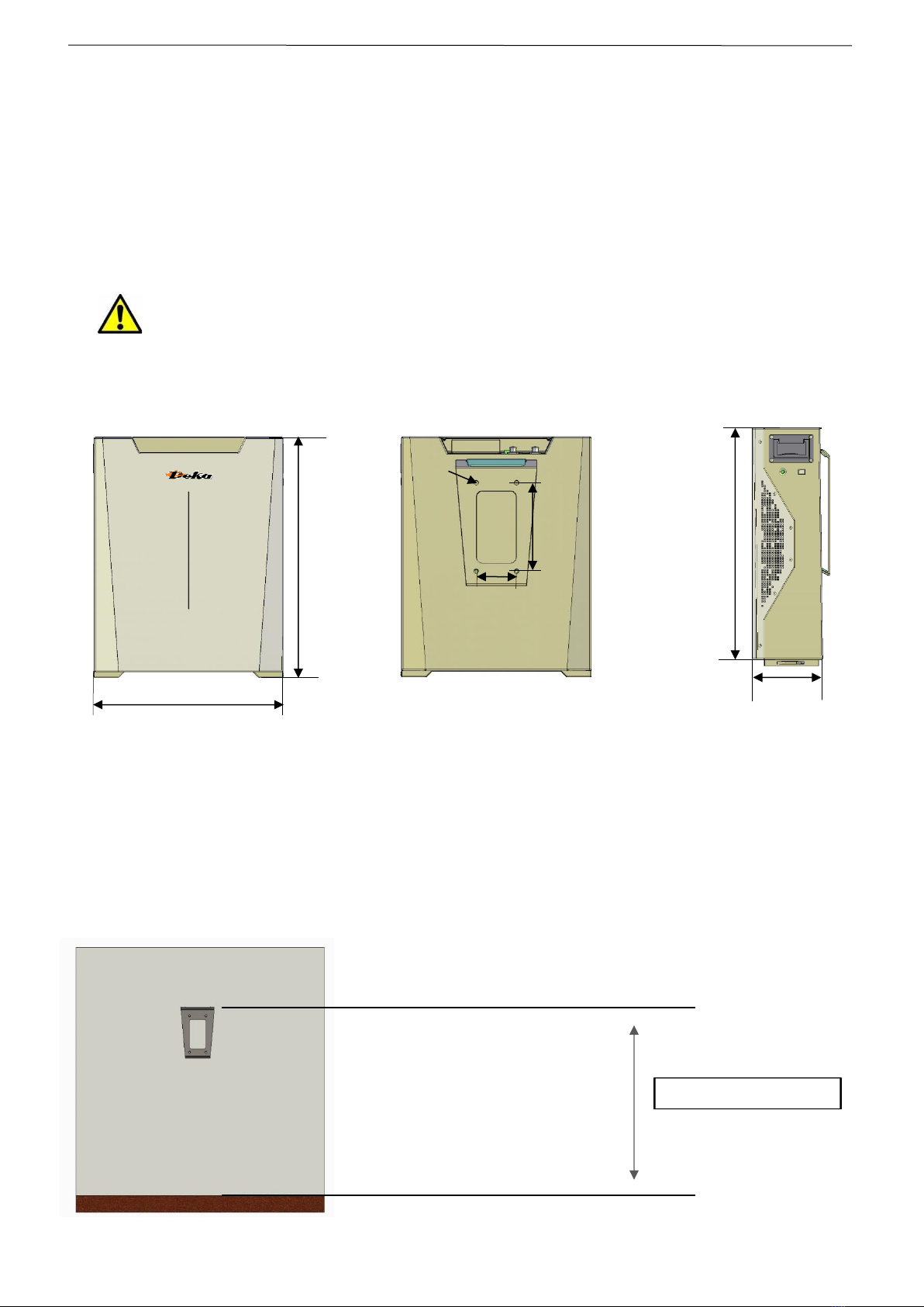
1.3.1 Battery Dimensions* (Wall Bracket)
*Dimensions are subject to construction tolerance +/- 1%
1.3.2 Wall Mount
Step 1: Install the wall bracket by using the wall plugs and screws contained in the battery kit.
The wall must be inspected before proceeding with the bracket installation. A local civil engineer should assess the correct
installation method, either wall mounted or floor mounted.
163 mm
580 mm
470 mm
593 mm
12 mm
100 mm
220 mm
100/120 cm suggested height

DEKA DURATION DD5300
20
ATTENTION:
The Battery Module weighs 126.3 lb (57.3 kg) and must be installed with the help of a mechanical lift, and/or with at
least two people equipped with suitable suction cups for mechanical lifting or lifting straps.
The Bracket must be installed on a flat and vertical wall.
The steel bracket must be flush to the wall without any empty spaces between the wall surface and the back side of
the bracket. Make sure to have adequate space to install the battery before proceeding with the installation.
Step 2: Install the battery by fitting the back bracket of the module with the wall bracket interlocking.
This operation must be conducted with a mechanical lifting device and/or with at least two specialized
installers. Make sure the Battery Module is stable and properly locked into the upper interlocking plug.
30 cm (min distance from the ceiling)
STEP 1A
100/120 cm suggested height
Max 140/150 cm (suggested battery heights)
Table of contents
Other Deka Batteries Pack manuals


