RedEarth DropBear User manual

DropBear_Installation Manual
RE_PROD_0011 Version #2 Page 1 of 20 Issue Date 28/07/2020
DropBear
Battery Energy Storage System
- On or Off-Grid -
(Single Phase)
Installation Manual

DropBear_Installation Manual
RE_PROD_0011 Version #2 Page 2 of 20 Issue Date 28/07/2020
RedEarth Energy Storage Ltd
15 Fienta Place
Darra – QLD 4076
Australia
Tel: +61 7 3279 6707
Email: [email protected]
Web: www.redearth.energy

DropBear_Installation Manual
RE_PROD_0011 Version #2 Page 3 of 20 Issue Date 28/07/2020
Safety procedures
WARNING: Working inside of the DropBear system is restricted to qualified personnel.
Installers must be qualified electricians with CEC accreditation for Solar and Battery.
The DropBear must only be installed by suitably qualified personnel.
Many of the procedures covered in the INSTALLATION sections of this manual have
inherent risks. Whilst the DropBear is designed to be safe, including residual current
device and double insulated cables, the voltages connected or generated by the
equipment are hazardous and potentially fatal.
The wiring diagrams and installation instructions are given as a guide only and
compliance to appropriate standards is the responsibility of the installer. Such
standards are listed below:
AS/NZS 3000:2018
Wiring rules
AS/NZS 5033:2014 (amdt 1&2)
Installation and safety requirements for
photovoltaic (PV) arrays
AS/NZS 4509.2:2012
Stand-alone power systems-Design
AS/NZS 1170.2:2011
Structural design actions-Wind actions
AS/NZS 4777.1:2016
Grid connection of energy systems via
inverters-Installation requirements
AS/NZS1768:2007
Lightning protection
AS/NZS 3008.1.1:2017
Electrical installations – Selection of cables
AS/NZS 5139:2019
Electrical installations-Safety of battery
systems for use with power conversion
equipment
In our efforts towards constant product enhancement, this document is subject to
change at any time. Please visit www.redearth.energy
and download the
appropriate and latest version manual.
If installing within 1km from coastal line, DropBear must be indoors

DropBear_Installation Manual
RE_PROD_0011 Version #2 Page 4 of 20 Issue Date 28/07/2020
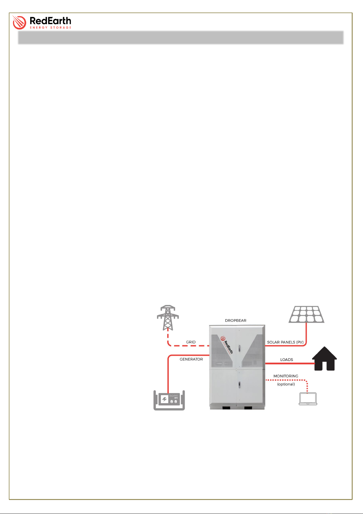
Your RedEarth DropBear is an AC coupled ready-to-run energy storage system for On or Off-Grid
applications. It comprises of a Fronius Primo Solar MPPT inverter, Selectronic SP Pro Battery
inverter, self-managed lithium batteries and is fully assembled and factory tested. It is ready to
connect a PV Solar array and generator with either auto or manual start.
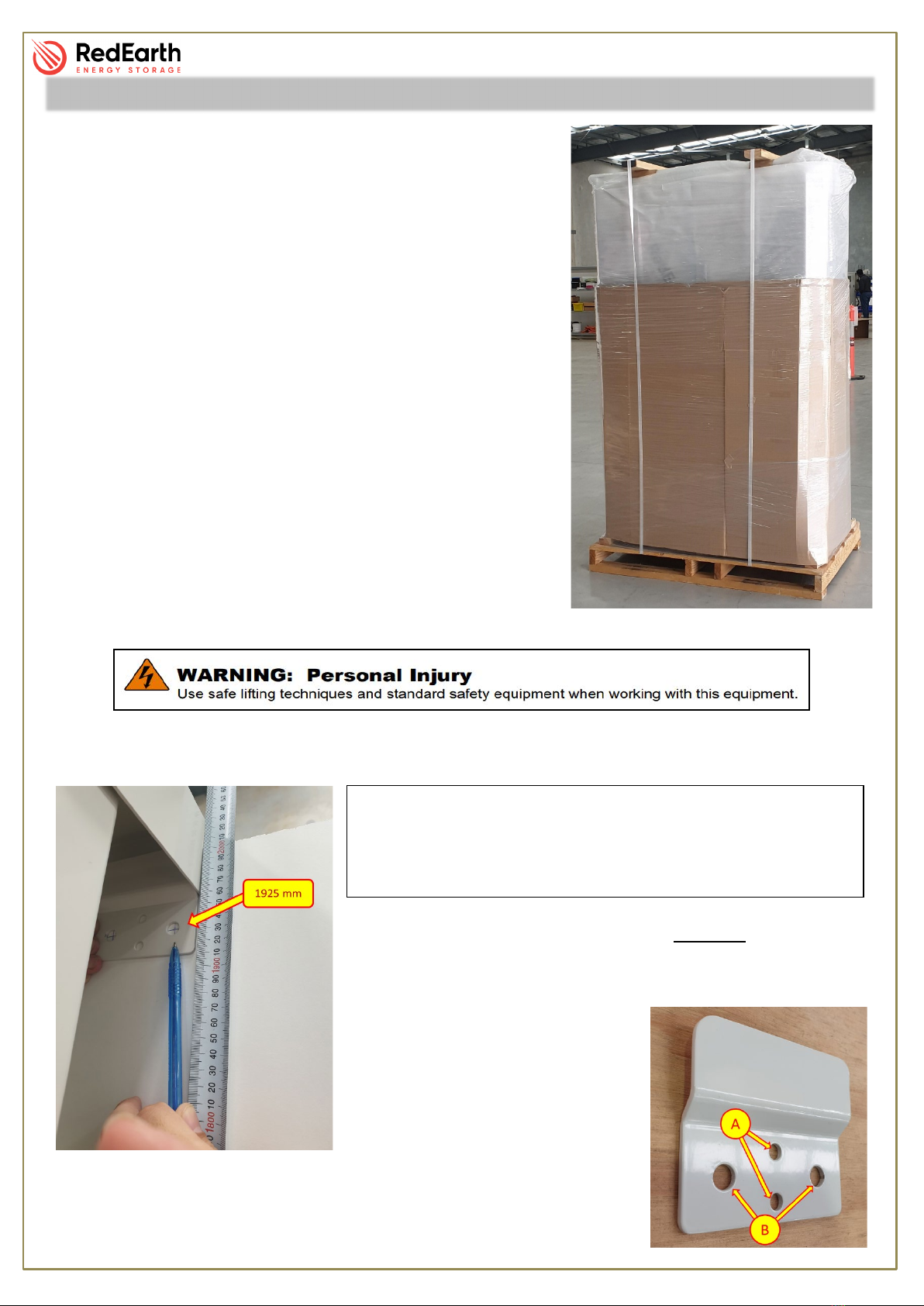
The DropBear is designed to be installed indoors or outside in a shaded and weather protected
environment against a wall. A changeover switch is included in case of system failure. In this case
the loads can then be run off a generator until the system is operational again.
RedEarth Energy can provide remote monitoring, technical support and service to ensure ongoing
operation of your DropBear. You can also access remote monitoring to view your consumption
online.
DropBear installations require the electrical connection of;
•The customers load – there are dedicated terminals inside the unit to connect to.
•Two arrays of PV solar panels which can be installed with different orientations.
•Generator - there are dedicated power, auto-start and battery charger terminals
inside the unit to connect to.
•Monitoring - The installer will need to connect the system to the internet via LAN
cable or 4G SIM-card. The details on how to set this up are explained in the
INSTALLATION - MONITORING section of this manual.
For a smooth installation, RedEarth offers installation training as well as a tech-support phone line
for any assistance regarding installation.
Note: The DropBear is not designed
to act as a main switch board for the
premises, as it does not include
space for additional main & customer
circuit breakers or RCDs. The MEN
link and Earth connection need to be
installed as per AS/NZS 3000:2018.
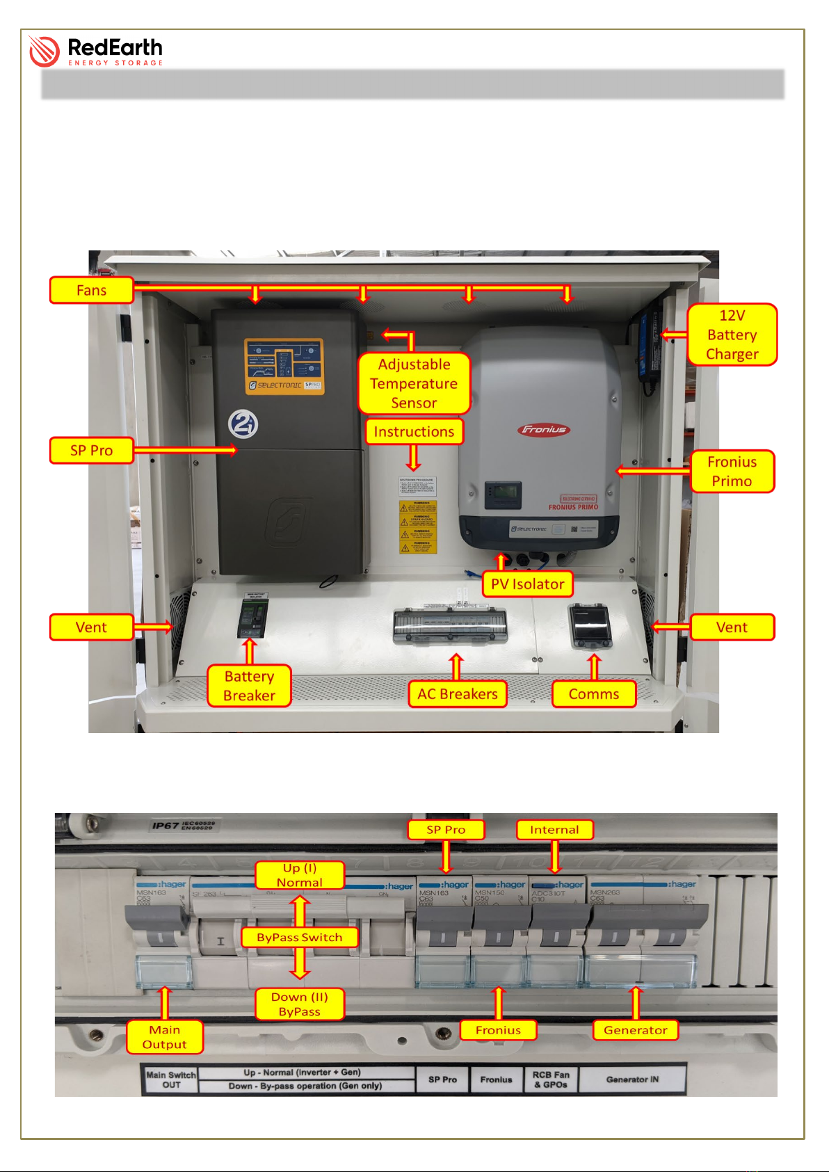
The DropBear undergoes factory
testing and commissioning at
RedEarth’s headquarters before
shipping. All parameters are pre-set for correct operation between the SP Pro inverter, the Fronius
and the battery bank. However, some parameters may need to be adjusted during installation (eg.
generator size, maintenance run, etc). Please consult DropBear Commissioning section in this
manual as well as the Selectronic Manual.
Overview

DropBear_Installation Manual
RE_PROD_0011 Version #2 Page 5 of 20 Issue Date 28/07/2020
DropBear Weight: 205kg without any Lithium batteries (42kg per battery)
Dimensions: 200.5 cm H x 131.4 cm W x 65.6 cm D
Physical Specifications
DropBear Minimum Clearance
Dimensions: 210 cm H x 166.7 cm W x 117.4 cm D

DropBear_Installation Manual
RE_PROD_0011 Version #2 Page 6 of 20 Issue Date 28/07/2020
Inside:
The DropBear has two main areas, one for the batteries and the other for the switches and
electronic equipment. Each section has a key-lockable double door.
The top enclosure contains all of the electric-electronic equipment, switches and AC connection
terminals.
The “AC Breakers” window shown below contains all the AC protective and isolation points and
the changeover switch. Each device is labelled for easy identification. Labels can be seen in the
picture below.
Components

DropBear_Installation Manual
RE_PROD_0011 Version #2 Page 7 of 20 Issue Date 28/07/2020
Behind the control panel, the following items are found:
The bottom enclosure consists of a robust and perforated base to support full weight of the
batteries and a front and rear rail to secure the batteries in place.
Because of lithium batteries properties, it is possible to install additional batteries in your system at
any time, please contact RedEarth for further details.
Components

DropBear_Installation Manual
RE_PROD_0011 Version #2 Page 8 of 20 Issue Date 28/07/2020
Attached to the top of this chamber there are two fully enclosed battery busbars with the correct
number of battery cables.
The DropBear comes fully equipped with the following items.
•DropBear pre-wired enclosure
•Selectronic inverter
•Fronius Primo inverter
•Parts Kit Box
o2x Wall mount bracket
oVarious screws/ Dyna-bolts for fixing base and wall
brackets
oPV and Battery Sticker Kit
oGlands and plain to screwed adapters
oMC4 connectors
oAerial for 4G
connection
•DropBear Installation Manual
•DropBear User Manual
•SP PRO user manual
•Fronius manual
•Battery Specifications
•Warranty Information
Components

DropBear_Installation Manual
RE_PROD_0011 Version #2 Page 9 of 20 Issue Date 28/07/2020
Transporting:
The DropBear system is supplied strapped down to a pallet.
It is fully ready to run. The system weighs around 205kg
without batteries. The system requires lifting equipment to
be removed from the pallet and placed in position.
The base of the system has spaces for either a forklift or a
standard trolley jack to be used.
If the DropBear is too heavy to manage the Inverters and
batteries can be removed and then replaced once the
system is in position. Each battery module weighs 42kg and
up to 12 can be installed in the system.
The DropBear is designed to be placed against a wall in a
shaded and weather protected area with the system
securely connected to the wall with the wall bracket
included. Air inlet vents are on the side and base of the
system. Do not block them, ensure they are kept clear at all
times
Step 1: Securing in position
At installation position, mark a height of 1925mm from the floor.
As shown in the picture on the left, this mark indicates the
centre of the large hole. The two brackets should be spaced so
that they securely fastened to the
wall (eg. wall studs).
The wall bracket has two sets of
different size holes “A”s and “B”s.
As illustrated (right), set “A” is for
screwing into a wall stud with the
screws (supplied) and set “B” is for a solid concrete/ brick wall to be
secured with Dyna-bolts (supplied).
Installation
IMPORTANT: Before positioning the DropBear, be sure
that there is an available area of 2100 x 1667 x 1174 (H x
W x D). This will allow a minimum of 90⁰ open door angle
as well as lateral ventilation.

DropBear_Installation Manual
RE_PROD_0011 Version #2 Page 10 of 20 Issue Date 28/07/2020
Once wall brackets are firmly attached to the wall, move the DropBear into place with the help of a
trolley jack (or forklift) lifting it high enough to clear the bracket and slide in behind it.
On the base of the DropBear, there is a hole at the front on each side. These holes are for
securing the base with supplied Dyna-bolts, then plug these holes with supplied 25mm plugs to
limit pest ingress.
Masking tape is strategically positioned in between the doors and the unit. These are common
rubbing spots and the purpose of the tape is to avoid paint chipping during transportation. This can
now be removed.
With the DropBear in place, rotate the handles on the top and bottom door counter-clockwise to
open the doors. Remove the Control covers by unscrewing all identified screws in above picture.
By doing this, you will have access to all AC and DC, wire connection terminals and the “Comm’s
Area”.
Installation

DropBear_Installation Manual
RE_PROD_0011 Version #2 Page 11 of 20 Issue Date 28/07/2020
Step 2: Electrically connect the DropBear
NOTE: Before proceeding any further, ensure that all breakers and isolators, as well as those
supplying power to the unit, are turned OFF.
AC Connections
All AC cables should be brought through the 25mm or 32mm holes on the left hand side of the
rear panel (behind battery breaker), secured with a gland (or plain-to-screwed adaptor if using
corrugated conduit), and attached to the correct terminals of the breaker as shown below.
Grid termination (if requested)
Active must terminate into the bottom side of the grid breaker. Earth and Neutral must be
terminated into an empty slot in their respective Busbar.
Load connection
Active must terminate into the bottom of the Load circuit breaker, as shown in the above picture.
Earth and Neutral must be terminated into the respective busbars.
NOTE: All other devices are already connected as per SLD available in the back of this manual.
Generator termination
Active and Neutral must terminate into the bottom of the generator circuit breaker. Earth must be
terminated into an empty slot in the Earth Bar.
Installation

DropBear_Installation Manual
RE_PROD_0011 Version #2 Page 12 of 20 Issue Date 28/07/2020
Generator Auto-Start and Charger
The DropBear contains four terminals in the Comms area. These terminals are displayed in the
picture on the next page and can be identified as:
•Gen Start: Dry-contact
The two terminals on the left must be connected to a cable to activate the generator auto-start.
•Positive Terminal (charger)
The third terminal from the left must be connected to the positive (+12V) terminal of the
generator’s battery.
•Negative Terminal (charger)
The fourth terminal from the left terminal must be connected to the negative (0V) terminal of the
generator’s battery.
GENERATOR REQUIREMENTS
Please ensure that your generator meets or exceeds the following specifications:
-Generator waveform THD: < 10%.
-Generator Vrms range: 180 ~ 264Vac
-Generator voltage crest factor (Vpeak/Vrms): < 1.6
-Generator peak voltage: <380V
-Frequency range: 45Hz ~ 55Hz
-Frequency slew rate: <0.3Hz/sec
NOTE: Inverter-generators are recommended for use with DropBear for their better power
quality. If voltage, frequency or current waveforms of the generator are not of a high enough
quality, then it will be rejected by the inverter.
For the SPMC481 (5kW), the recommended generator size by Selectronic is around 9.5kVA.
For the SPMC482 (7.5kW), the recommended generator size by Selectronic is around 14kVA.
Installation

DropBear_Installation Manual
RE_PROD_0011 Version #2 Page 13 of 20 Issue Date 28/07/2020
DC Connections
Battery
The batteries are located in the lower enclosure, behind the bottom double doors.
If supplied separately, unbox the batteries, place them on the battery shelf, re-install the front
battery rail and finally attach the battery cables.
PV Connections
The PV cables should be brought through the 25mm holes on the right-hand side of the unit using
the supplied plain to screwed adapters.
The PV cables should then be terminated with the MC4’s connectors provided and then plugged
into the pre-terminated tails. (one tail per string)
If the tails are not needed, the installer can remove the Fronius from its wall-mount and terminate
the cables in the appropriate terminals. Or additional strings can be added if required.
Installation

DropBear_Installation Manual
RE_PROD_0011 Version #2 Page 14 of 20 Issue Date 28/07/2020
Monitoring Connection
The Dropbear uses a SwitchDin Utility Droplet Controller to provide remote monitoring for the
system. The Utility Droplet Controller is a high-end but simple device that will allow RedEarth to
monitor and provide accurate information on the system operation.
See below how to correctly install the Droplet.
Ports on the Droplet that are not identified here, must not be used.
Setup
1. Connect the Selectronic inverter to one of the Droplet’s USB ports using the cable already
in place inside the DropBear.
2. Plug the power supply into the power port of the droplet.
3. Place the antenna outside of the unit, run the cable through the supplied 16mm gland and
then attach to the droplet.
4. Connect the droplet to internet.
a) Wired Connection (recommended)
Connect a standard Ethernet cable between the Droplet and an on-premises
internet router. It should simply start working once plugged in. This is the
simplest and most reliable connectivity option.
b) 4G Cellular network
Connect the provided antenna to the droplet. Place antenna in a suitable
position outside the DropBear enclosure.
(Note that if installing both the wired connection and 4G, the SwitchDin will automatically
switch between the two if it loses signal from one source)
Installation

DropBear_Installation Manual
RE_PROD_0011 Version #2 Page 15 of 20 Issue Date 28/07/2020
The DropBear is commissioned and tested in factory to guarantee correct operation. However,
some last-minute parameter adjustments may be required (eg. generator size or warm-up time).
Carefully follow the procedure below on how to make these alterations without compromising the
existing configuration.
NOTE: This must be done by a qualified person.
NOTE: The program Selectronic SP Link can be downloaded from Selectronic’s web page
(http://www.selectronic.com.au/)
Step #1:
With the system powered, connect a computer to the Selectronic SP Pro using the USB cable
from the back of the SwitchDin.
Step #2:
Open the program “Selectronic SP Link”. The following page shall appear:
In the Easy Start Guide window, click on “Advanced Configuration”.
Commissioning

DropBear_Installation Manual
RE_PROD_0011 Version #2 Page 16 of 20 Issue Date 28/07/2020
Step #3
Click on the “Connection” tab and then on “Connect”.
The program will request you to “Save Site” before proceeding. Fill in a site name and then click
“Save Site”.
Commissioning

DropBear_Installation Manual
RE_PROD_0011 Version #2 Page 17 of 20 Issue Date 28/07/2020
Step #4
Click on “Configuration Settings” tab and then on the “Get SP PRO’s Configuration” button to
download existing settings from the SP Pro to your laptop.
Step #5
Adjust the required parameters (any altered settings will be highlighted in yellow) and then click on
the “Configure SP PRO” button to send the new settings back to the SP Pro.
NOTE: In case of a factory reset on the parameters, the installer may contact RedEarth Energy
Storage and by providing the DropBear’s serial number request the configuration file.
Tech Support:
•+61 (4) 8700 2451
•+61 (7) 3279 6707.
Commissioning

DropBear_Installation Manual
RE_PROD_0011 Version #2 Page 18 of 20 Issue Date 28/07/2020
Once the DropBear is in place and correctly installed, you may start the system.
To power up the unit you must follow the steps below:
1. Turn on individual battery breakers.
This will charge up the capacitors inside the inverters. The LED on the inverter will flash and beep.
Wait for approximately 10 seconds.
2. Turn on the Main Battery Breaker.
3. Turn on the PV isolator located under the Fronius Primo.
Before step 4, the inverters are powered up but not inverting (outputting AC power).
4. Turn ON the Selectronic by pressing and holding the “ON” button on the top left-hand-side
of the inverter.
5. Turn on all AC circuit breakers.
The following shutdown procedure should be followed:
Start-up / Shutdown Procedure

DropBear_Installation Manual
RE_PROD_0011 Version #2 Page 19 of 20 Issue Date 28/07/2020
RedEarth is available to assist commissioning the system during business hours.
Phone Tech support on +61 487 002 451 or +61 7 3279 6707.
RedEarth also provides training in our facility in Brisbane. Training can potentially be arranged at
your facilities if requested.
Our website, www.redearth.energy includes updated documents as they become available.
Options available from RedEarth
RedEarth can provide several options for the DropBear
•Additional batteries for system expansion.
•Extended warranty options.
•Miscellaneous spare parts (including indicator lights for Generator start)
•Solar kits with combiner boxes, PV panels, racking and pre-terminated PV cables
•Diesel Generator with 2-wire auto start.
•Generator backup kit (for on-grid applications)
•Ongoing remote monitoring – Concierge RED service.
RedEarth support options

DropBear_Installation Manual
RE_PROD_0011 Version #2 Page 20 of 20 Issue Date 28/07/2020
Single Line Diagram (SLD)
Other manuals for DropBear
2
Table of contents
Other RedEarth Batteries Pack manuals

RedEarth
RedEarth BlackMax User manual

RedEarth
RedEarth SunRise SRS-3 Series User manual

RedEarth
RedEarth SunRise SRS-3 Series User manual

RedEarth
RedEarth TROPPO-4841 User manual

RedEarth
RedEarth BlackMax User manual

RedEarth
RedEarth DropBear User manual

RedEarth
RedEarth HoneyBadger User manual

RedEarth
RedEarth BlackMax User manual
Popular Batteries Pack manuals by other brands

Tripp Lite
Tripp Lite External Battery Pack BP240V1507C specification

Tripp Lite
Tripp Lite Shallow-Depth External Battery Pack... Specifications

Powerplus
Powerplus POWAIR0011 manual

Tripp Lite
Tripp Lite AG-01A2 Series owner's manual

Tripp Lite
Tripp Lite BP24V33 owner's manual

Sofar solar
Sofar solar BTS Series user manual