Deka HRC800 User manual
1
STATIONARY BATTERY INSTALLATION
AND OPERATING INSTRUCTIONS
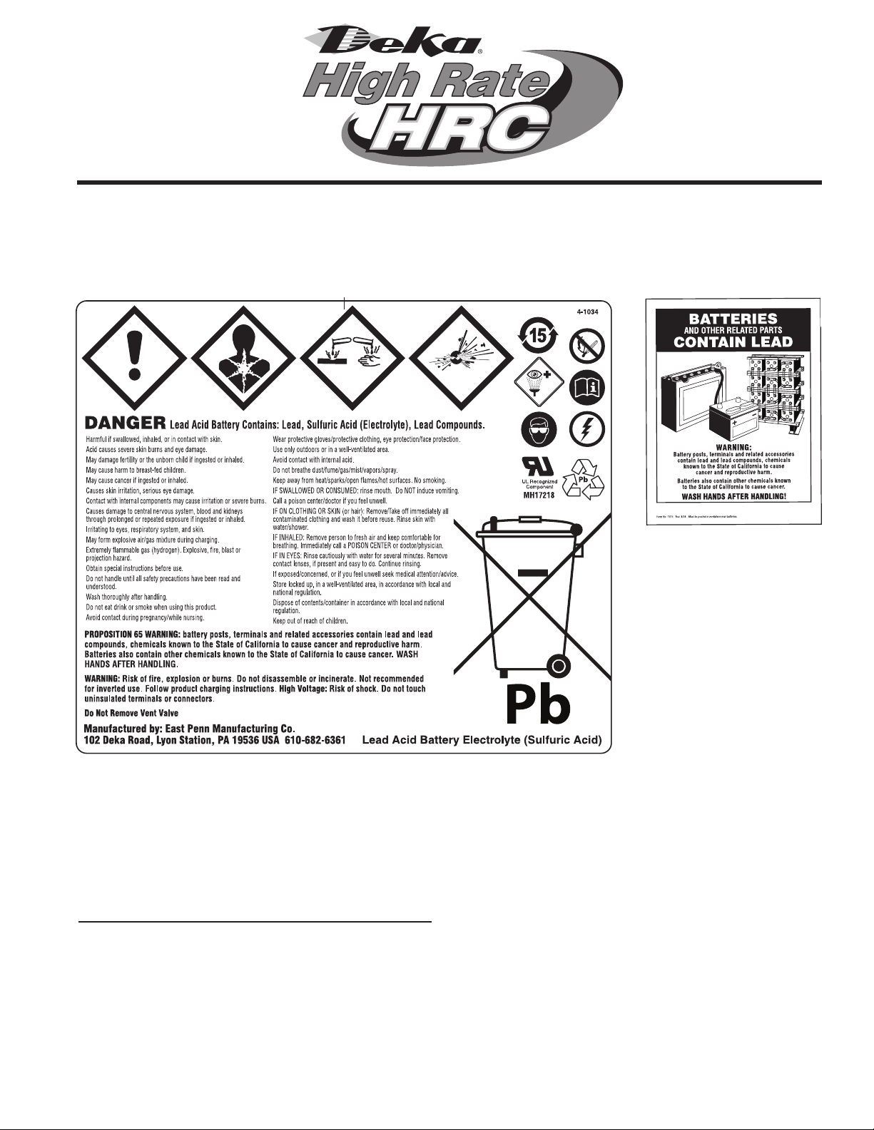
SAFETY PRECAUTIONS
Although all valve regulated batteries have the
electrolyte immobilized within the battery, the
electrical hazard associated with batteries still exists.
Work performed on these batteries should be
done with the tools and the protective equipment
listed below. VRLA battery installations should be
supervised by personnel familiar with batteries and
battery safety precautions.
WARNING: Risk of fire, explosion or burns. Do not
disassemble, heat above 65°C, or incinerate.
IN REFERENCE TO THIS MANUAL:
– “Battery” is defined as an individual 12-volt unit.
– “Battery string” is defined as a series connected elec-
trical system comprised of batteries
(individual 12-volt units).
Protective Equipment
Although VRLA batteries can vent or leak small
amounts of electrolyte, electrical safety is the principle
but not the only concern for safe handling. Per IEEE
1188 recommendations, the following minimum set
of equipment for safe handling of the battery and
protection of personnel shall be available:
1. Safety glasses with side shields, or goggles, or face
shields as appropriate. (Consult application specific
requirements)
2. Electrically insulated gloves, appropriate for
the installation.
3. Protective aprons and safety shoes.
4. Portable or stationary water facilities in the battery
vicinity for rinsing eyes and skin in case of contact
with acid electrolyte.
5. Class C fire extinguisher.
6. Acid neutralizing agent.

22
Protective Equipment cont.
7. Adequately insulated tools (as defined by ASTM F1505
“Standard Specification for Insulated and Insulating
Hand Tools”).
8. Lifting devices of adequate capacity, when required.
Procedures
The following safety procedures should be followed:
Always wear safety glasses or face shield when
working on or near batteries.
1. These batteries are sealed and contain no free elec-
trolyte. Under normal operating conditions, they do
not present any acid danger. However, if the battery
case or cover is damaged, acid could be present.
Sulfuric acid is harmful to the skin and eyes. Flush
affected area with water immediately and consult
a physician if splashed in the eyes. Consult SDS for
additional precautions and first aid measures.
SDS sheets can be obtained at
www.eastpennmanufacturing.com
2. Prohibit smoking and open flames, and avoid
arcing in the immediate vicinity of the battery.
3. Do not wear metallic objects, such as jewelry, while
working on batteries. Do not store un-insulated tools
in pockets or tool belt while working in vicinity of
battery.
4. Keep the top of the battery dry and clear of tools and
other foreign objects.
5. Provide adequate ventilation (per IEEE standard
1187 and/or local codes) and follow recommended
charging voltages.
6. Never remove or tamper with the pressure relief
valves. Warranty void if vent valve is removed.
7. Inspect all flooring and lifting equipment
for functional adequacy.
8. Adequately secure battery modules, racks, or cabinets
to the floor.
9. Connect support structures to ground system
in accordance with applicable codes.
10. The below IEEE Standards contain additional informa-
tion. Other standards may be relevant to your specific
application.
IEEE 1184 – Guide for Batteries for UPS Systems
IEEE 1187 – Recommended Practice for
Installation Design of VRLA Batteries
IEEE 1188 – Recommended Practice
for Maintenance, Testing, of VRLA Batteries
IEEE 1189 – Selection of VRLA
Batteries for Stationary Applications
RECEIVING & STORAGE
Receiving Inspection
Upon receipt, and at the time of actual unloading,
each package should be visually inspected for any
possible damage or electrolyte leakage. If either the
entire shipment should be conducted and noted on
the bill of lading. Record receipt date, inspection date
and notify carrier of any damage.
Unpacking
1. Always wear eye protection.
2. Check all batteries for visible defects such as cracked
containers, loose terminal posts, or other unrepairable
problems. Batteries with these defects must be
replaced.
3. Check the contents of the packages against the
packaging list. Report any missing parts or shipping
damage to your East Penn agent or East Penn Mfg.
Co. immediately.
4. Never lift batteries by the terminal posts.
Storage / Refresh
Batteries should be installed, and float charged
upon delivery. If batteries are to be stored, the below
requirements shall be followed.
1. Batteries shall be stored indoors in a clean, level, dry,
cool location.
2. Store, charge, and ship in vertical position only.
3. Recommended storage temperature is 50°F (10°C) to
77°F (25°C). Acceptable storage temperature is 0°F
(-18°C) to 90°F (32°C).
4. The batteries shall be given a refresh charge at
regular intervals as detailed below:
0°F(-18°C) to 77°F (25°C)
Batteries shall be charged by the
“battery charge date” marked on pallet.
Successive recharges shall be
performed every 6 months.
78°F (26°C) to 90°F (32°C)
Battery voltage readings shall be taken monthly.
Batteries must be given a refresh charge within 3
months from date of receipt or if any battery voltage
falls below 12.72 volts per battery, whichever occurs
first.
Successive refresh charges shall be performed every
3 months.
5. Whenever a refresh charge is required, it’s important
that all batteries to be installed in the same series
string receive a charge at the same time to ensure
continuity once placed in their intended application.
6. Each battery shall be charged for 24 hours at a
constant voltage equal to 14.40 volts per battery. To
ensure the batteries are fully charged within 24hrs,
the charger used for this refresh charge must have
the capacity to provide at least the minimum charge
current specification and not exceed the maximum
charge current for the given battery type (model), as
called out in Appendix C.
33
Grounding
When grounding the battery string, proper techniques
should be applied per electrical standards such as
NEC and/or Federal, State and Local codes, as well as
User Manual of specific application.
Cabinets
Cabinet systems come factory assembled and
prewired. Do not tip or turn cabinets on their sides
when positioning them in their intended installation
area. Cabinets must be used in an upright position.
These systems are pre-connected. Only inter-shelf,
inter-cabinet and connections to the load are required.
See the connection diagram inside the cabinet. Inter-
cabinet and load connection cables are not included.
Racks
Assemble racks in accordance with the intended
arrangement, align with a level and bolt to the floor.
See rack assembly instructions.
Storage / Refresh cont.
7. All requested information on “Refresh Record Form”
in Appendix A should be completed for each refresh
charge.
8. Batteries shall not be stored beyond 12 months.
Storing beyond 12 months will affect warranty.
9. If the storage / refresh requirements cannot be
met, contact the East Penn Reserve Power Product
Support Department for alternate instructions.
INSTALLATION
General
Caution should be taken when installing batteries to
insure no damage occurs. The battery string cabinet,
tray, rack, etc. shall be inspected for sharp edges that
could cause damage to the battery casing. Batteries
shall not be dropped, slid, or placed on rough or
uneven surfaces such as tray lips or grated flooring.
Mishandling of batteries could result in equipment
damage or human injury. East Penn will not be liable
for damage or injury as a result of mishandling or
misuse of the product.
FOR ANY OTHER INSTALLATION ORIENTATION, THE PRODUCT WILL NOT BE WARRANTED.
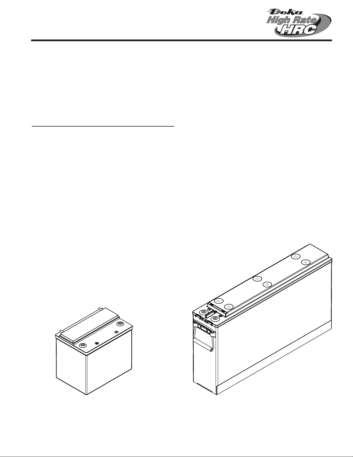
DEKA HRC BATTERIES ARE TESTED AND APPROVED TO
BE INSTALLED AND OPERATED IN THEIR UPRIGHT POSITION.
Terminals – Upright Position Terminals – Upright / Front Position
TOP TERMINAL BATTERY
FRONT TERMINAL BATTERY

44
SYSTEM OPERATIONS
Charger Voltage
These batteries are designed for continuous
float applications.
FLOAT / STANDBY (per battery)
13.50V +/- 0.06 @ 77°F (25°C)
When setting the float voltage on the charger, the
battery string should be set to float at the nominal
battery float voltage times the number of batteries
in the string. The charger must be able to maintain
the system voltage within ± 0.5% of the desired level
at all times. The desired float voltage varies with
temperature. Consult Voltage Compensation Chart
(Pg. 8 – Appendix B).
TEMPERATURE COMPENSATION
Battery voltage should be adjusted for ambient
temperature variations.
12mV per °C (1.8°F) per 12V battery
Consult Voltage Compensation Chart
(Pg. 8 – Appendix B) for temperature compensation
voltage maximum and minimum limits.
Charger Current
Charge currrent should not exceed the recommended
min. and max. requirements. Consult Appendix C for
min. and max. charge current limits.
Battery Voltage
Although the charger must maintain the system volt-
age within ± 0.5%, individual battery voltages may
vary by ± 0.30V per battery of the average battery
string float voltage.
Equalizing
Upon installation of the battery string, an optional
charge of 14.40V per battery ± 0.06 @ 77°F (25°C) for
24 hours (not to exceed 24 hours) can be applied.
(NOTE: Verify that the higher battery voltage will not
adversely affect any other connected equipment). If
this is done, be sure to reset the charging equip-
ment to the proper float voltage.
Battery Operation
Battery operating temperature will affect battery string
capacity and operating life.
Temperatures greater than 77°F (25°C) will reduce
the operating life of the battery. For every 13°F (7°C)
increase in operating temperature above 77°F (25°C),
the warranty period will be proportionally reduced by
50% as shown below:
Venting
Under normal operation, VRLA batteries emit hydro-
gen gas, which is combustible at certain concentra-
tions. Proper ventilation should be provided per IEEE
1187 and/or local codes. Some batteries are designed
to accommodate the use of vent tubing. Ventilation
equipment is not designed or supplied by East Penn
Mfg. Safe installation of any venting equipment is the
responsibility of the installer.
BATTERY ASSEMBLY
(ALWAYS WEAR EYE PROTECTION.)
1. Set up the battery string so that the positive post (+)
of one battery is connected to the negative post (–) of
the next battery for all series connections. The inter-
battery connector contact surfaces shall be cleaned
by rubbing gently with a non-metallic brush or pad
before installing connectors.
Only approved oxide inhibitors (No-Ox-ID “A” from
Sanchem, Inc.) may be applied to connections or
battery posts.
2. For future identification, individual batteries should
be numbered in electrical connection sequence,
beginning with number one (1) at the positive end of
the battery string.
3. Install all interbattery connectors using lock washer
and bolts loosely to allow for final alignment of bat-
teries, then torque to 100 in lb +/- 5. After torquing the
connections on racked batteries, read the voltage of
the battery string to assure that individual batteries
are connected correctly. The total voltage should be
approximately equal to the number of batteries times
the measured voltage of one battery (when connected
in series). If the measurement is less, recheck the con-
nections for proper voltage and polarity.
4. Read and record interbattery connection resistance
and note the method of measurement. This helps
determine a satisfactory initial installation and can
be used as a reference for future maintenance
requirements. See Battery Maintenance Report. (Pg.
10 – Appendix D ). Clean, remake and re-measure any
connection having a resistance measurement greater
than 10% of the average of all the same type of
connections (interbattery, inter-tier or shelf, inter-rack
or intercabinet).
5. Battery performance is based on the output at the
battery terminals. Therefore, the shortest electrical
connections between the battery string and the
operating equipment results in maximum total battery
string performance.
Do not select cable size on current carrying capability
only. Cable size should not provide a greater voltage drop
between the battery system and operating equipment
than specified. Excess voltage drop will reduce the
desired support time of the battery system.
Operating Temperature Proportional Percentage
(%) of Life
ºF ºC
77 25 100%
81 27 80%
87 30 60%
90 32 50%

55
Battery Operation cont.
The battery string operating temperature should
not exceed 95°F (35°C) and should never exceed
105°F (40.5°C) for more than an eight-hour period.
If operating temperatures are expected to be
in excess of 95°F (35°C), contact East Penn for
recommendations.
Discharging at temperatures less than 77°F (25°C)
will reduce the capacity of the battery. If operating
temperatures are expected to be less than 50°F
(10°C), contact East Penn for recommendations.
The battery string must be located in a manner that
the individ¬ual batteries do not vary by more than
5°F (2.8°C) between the lowest and highest individual
battery temperatures.
Rectier Ripple Voltage
FREQUENCY
Ripple that has a frequency greater than 667Hz
(duration less than 1.5ms) is acceptable, unless it is
causing additional battery heating.
Ripple that has a frequency less than 667Hz (duration
greater than1.5ms), must meet the following voltage
specification to be acceptable.
VOLTAGE SPECIFICATION
Ripple voltage shall be less than 0.5% peak to peak
of the manufacturer’s recommended battery string
voltage.
Failure to comply can void the warranty.
RECORD KEEPING
Voltages, Temperatures & Ohmic
READINGS
Record keeping is an important part of stationary
battery maintenance and warranty coverage. This
information will help in establishing a life history of
the battery string and inform the user if and when
corrective action needs to be taken. Consult Battery
Maintenance Report. (Pg. 10 – Appendix D).
While it is acceptable to operate at temperatures less
than 77°F (25°C), it will require longer charging time to
become fully recharged. Also, the capacity will be less
at operating temperatures below 77°F (25°C).
After installation and when the battery string has
been on float charge for one week, the following data
should be recorded:
1. Battery string voltage at battery terminals while
battery is on float charge.
2. Charger voltage at charger panel meter.
3. Individual battery float voltages.
4. Ambient temperatures within area of battery string.
READINGS cont.
5. Terminal connections should be checked to verify
that the installer did torque all connections properly
to 100 in lb +/- 5. Micro-ohm readings should be
taken across every connection. Refer to meter
manufacturer’s instructions for proper placement of
probes. If any reading differs by more than 20% from
its initial installation value, re-torque the connection
to 100 in lb +/- 5. If reading remains high, clean con-
tact surfaces according to Step 1 under Battery
Assembly.
Failure to maintain proper records including
information as detailed above may result in
voiding any applicable warranty.
ACCEPTANCE TESTING
Each battery should be at 100% State of Charge
prior to performing an acceptance test on the battery
system. To ensure the batteries are fully charged the
following charge schedule should be followed.
Batteries should be charged at the equalization rate
of 14.40 volts per battery for 24 hours. Temperature
compensated charging parameters shall be applied as
detailed in “Voltage Compensation Chart” in Appendix
B of this manual.
To ensure the batteries are fully charged within 24hrs;
the charger used for this charge must have the current
equal to the maximum charge current for the given
battery type (model), as called out in Appendix C of
this manual.
If these requirements cannot be met, contact the
East Penn Product Support Department for alternate
instructions.
Upon completion, the charge voltage should be low-
ered to the float voltage of 13.50 volts per battery
for a minimum period of 72 hours. Reference: IEEE
1188-2005 Section 7.2 for additional acceptance test
requirements.
Upon completion of the above charge, the desired
acceptance test can be performed.
NOTE: There shall be no discharges of any duration
between the start of the equalization and the comple-
tion of the float period. If a discharge does occur, the
charging regime detailed above shall be repeated.
Upon completion of the acceptance test, the battery
system should be placed on float charge at 13.50 volts
per battery to restore the battery to its’ rated capacity.
Batteries should not require an equalization charge
once they have passed their initial acceptance
test. Consult with the East Penn Product Support
Department before performing additional equalizing
charges on batteries that have successfully passed
their initial acceptance test.

66
MAINTENANCE
Always wear eye protection when working on or near
batteries. Keep sparks and open flames away from
batteries at all times. Review “Safety Precautions”
(Pg. 1).
Annual Inspection(1)
1. Conduct a visual inspection of each battery.
2. Record the battery string voltage at battery terminals
while battery is on float charge.
3. Record the charger voltage at charger panel meter.
4. Record the individual battery voltages. The accuracy
of the DMM (Digital Multimeter) must be 0.05% (on
dc scale) or better. The DMM must be calibrated to
NIST traceable standards. Because float readings are
affected by discharge and recharges, these readings
must be taken when the battery string has been on
continuous, uninterrupted float for at least one month.
Battery should be within ± 0.30 volts of the average
battery string voltage.
5. Record the ambient temperatures.
6. Record the battery string temperature at the
negative terminal.
7. Record individual battery Ohmic readings.
8. Record all interbattery and terminal connection
resistances. Micro-ohm readings should be taken
during this inspection. If any reading differs by more
than 20% from initial readings taken, retorque the
connection. Retourque value is equal to initial torque
value as indicated in BATTERY ASSEMBLY section.
Recheck the micro-ohm reading. If the reading
remains high, clean the contact surface according to
installation portion of this manual.
(1) Other Maintenance Inspection intervals follow
IEEE 1188
Battery Cleaning
Do not use any chemical compounds to clean
batteries. Batteries, cabinets, and racks, shall
only be cleaned with: clear water, a mixture of
baking soda and water or East Penn Mfg battery
cleaner (part # 00321).
Any other types of chemical compounds or
solvents other than listed above, to clean the
battery may damage the battery case and / or
cover causing possible exposure to sulfuric acid.
Capacity Testing
Per IEEE 1188 “Capacity testing is used to trend
battery aging. The result of a capacity test is a
calculation of the capacity of the battery. The
calculated capacity is also used to determine if
the battery requires replacement.”
When performing capacity testing and recording data
refer to IEEE 1188 recommendations.
NOTE: When discharging at higher rates, extra
connectors may need to be added to prevent
excessive voltage drop and/or excessive
temperature rise.
Should it be determined that only individual
battery(ies) need to be replaced, contact East Penn.

APPENDIX A
REFRESH RECORD FORM
EPM Order Number* Pallet ID Number Individual Performing Test (Full Name) Date of
Refresh Refresh Duration
Model
Number
Information Prior to Refresh Information within 1 hour of
Refresh Completion
Notes & Comments
Date
Code
Battery
Serial
Number
Open Circuit Voltage
Battery
Voltage
Reading
Charging
Current
Battery
Temperature
Battery 1
Battery 2
Battery 3
Battery 4
Battery 5
Battery 6
Battery 7
Battery 8
Battery 9
Battery 10
Battery 11
Battery 12
Battery 13
Battery 14
Battery 15
Battery 16
Battery 17
Battery 18
Battery 19
Battery 20
Battery 21
Battery 22
Battery 23
Battery 24
ALL FIELDS TO THE RIGHT OF THE CELL NUMBER ABOVE MUST BE COMPLETED
EPM ORDER NUMBER WILL APPEAR ON THE SHIPPING LABEL ON THE CARTON COVERING EACH PALLET OF CELLS
TO ENSURE CONTINUATION OF WARRANTY, SUBMIT FORMS TO: East Penn Mfg. Co, Inc.,

8
APPENDIX B
VOLTAGE COMPENSATION CHART
°C Float Equalize °F
>35 13.38 14.28 >95
34 13.39 14.29 93.2
33 13.40 14.30 91.4
32 13.42 14.32 89.6
31 13.43 14.33 87.8
30 13.44 14.34 86.0
29 13.45 14.35 84.2
28 13.46 14.36 82.4
27 13.48 14.38 80.6
26 13.49 14.39 78.8
25 13.50 14.40 77.0
24 13.51 14.41 75.2
23 13.52 14.42 73.4
22 13.54 14.44 71.6
21 13.55 14.45 69.8
20 13.56 14.46 68.0
19 13.57 14.47 66.2
18 13.58 14.48 64.4
17 13.60 14.50 62.6
16 13.61 14.51 60.8
15 13.62 14.52 59.0
14 13.63 14.53 57.2
13 13.64 14.54 55.4
12 13.66 14.56 53.6
11 13.67 14.57 51.8
<10 13.68 14.58 <50
12mV per ˚C

9
APPENDIX C
DEKA HRC CHARGE CURRENT LIMITS
Battery Type Max. Charge
Current (A)
Max. Charge
Current (A)**
HRC800 17.2 5.2
HRC950 24.4 7.3
** = Using minimum charge current will extend recharge time
and increase risk of battery being undercharged

10
APPENDIX D
BATTERY MAINTENANCE REPORT
Charger Output _____________________ Amp Air Temperature ______________________°F
Total Battery String Voltage ________________ Panel Meter Volts ______________________
Unit Ohms or Unit Ohms or Unit Ohms or Unit Ohms or Unit Ohms or Unit Ohms or
No. Volts Mhos No. Volts Mhos No. Volts Mhos No. Volts Mhos No. Volts Mhos No. Volts Mhos
Inspection Date _____________________________________________________________________ No. of Units/String __________________
Company___________________________________________________________________________ Type _______________________________
Address ____________________________________________________________________________ Date New __________________________
Battery location and/or number ______________________________________________________ Date Installed _______________________
Readings Taken By ____________________________ Remarks/Recommendations ___________________________________________________________
Readings should be taken at installation and annually thereafter.
1 41 81 121 161 201
2 42 82 122 162 202
3 43 83 123 163 203
4 44 84 124 164 204
5 45 85 125 165 205
6 46 86 126 166 206
7 47 87 127 167 207
8 48 88 128 168 208
9 49 89 129 169 209
10 50 90 130 170 210
11 51 91 131 171 211
12 52 92 132 172 212
13 53 93 133 173 213
14 54 94 134 174 214
15 55 95 135 175 215
16 56 96 136 176 216
17 57 97 137 177 217
18 58 98 138 178 218
19 59 99 139 179 219
20 60 100 140 180 220
21 61 101 141 181 221
22 62 102 142 182 222
23 63 103 142 183 223
24 64 104 144 184 224
25 65 105 145 185 225
26 66 106 146 186 226
27 67 107 147 187 227
28 68 108 148 188 228
29 69 109 149 189 229
30 70 110 150 190 230
31 71 111 151 191 231
32 72 112 152 192 232
33 73 113 153 193 233
34 74 114 154 194 234
35 75 115 155 195 235
36 76 116 156 196 236
37 77 117 157 197 237
38 78 118 158 198 238
39 79 119 159 199 239
40 80 120 160 200 240
Avg. Voltage Avg. Voltage Avg. Voltage Avg. Voltage Avg. Voltage Avg. Voltage
Individual
Battery Readings

11
Page Intentionally Blank

All data subject to change without notice. No part of this document may be copied or
reproduced, electronically or mechanically, without written permission from the company.
E.P.M. Form No. 2531 02/22 © 2022 by EPM Printed in U.S.A.
East Penn Manufacturing Co. Lyon Station, PA 19536-0147 Phone: 610-682-3263 Fax: 610-682-4781 www.dekabatteries.com
This manual suits for next models
1
Table of contents
Other Deka Batteries Pack manuals


