Sun Fun Kits LF280K User manual

Sun Fun Kits V3.5 Assembly Manual
Revision 1.3

Before you Begin:
Thank you for purchasing your Sun Fun Kits V4 DIY heated battery kit, diy battery kits make
assembling your battery quick and easy and only require basic tools and hardware to assemble.
We recommend having a basic understanding of DC wiring in order to assemble your battery
pack and you will also need the following tools:
● Hex driver set: 3mm, 4mm, 5mm, and 8mm
● Insulated drives for securing bolts
● Thread locking compound (such as blue Loctite)
● Kapton or PET tape 1” to 2” in width
● Double Sided Sticky tape
● Velcro style loop
● DC Voltmeter
● Standard scissors
● 90% isopropyl alcohol.
● Adjustable DC Power Supply that is able to charge up battery cells (3.65 volts, 20 Amps)
if manually balancing or standard 13.6v to charge the battery.
● 300-400 grit sandpaper
Optional:
● Electrical Safe Silicone sealant (for those looking to make a water resistant battery)
● Hot glue gun (if you wish to secure wires using this method)
Page: 2 V3.5 Manual - Revision 1.3

Video Manual (V3 Manual):
If you are more of a visual learner, you can view the build process on our official youtube
channel: https://youtu.be/tWm65Pu0GuI
Preparing your battery cells:
Sun Fun Kits DIY battery kits support various prismatic cells, in this manual we will be using the
EVE LF304 type, however the process is the same for other manufacturers such as CATL,
REPT, Ganfeng and more, the V3 Kit includes spacers and other items to ensure maximum
compatibility for cells in this class (270-320 AH)
Page: 3 V3.5 Manual - Revision 1.3

Certified Automotive Grade Cells generally do not require balancing; however, you may choose
to balance your cells, we have a video explaining this process.
This process is explained in this tutorial video:
https://www.youtube.com/watch?v=JGbZozzCYvM
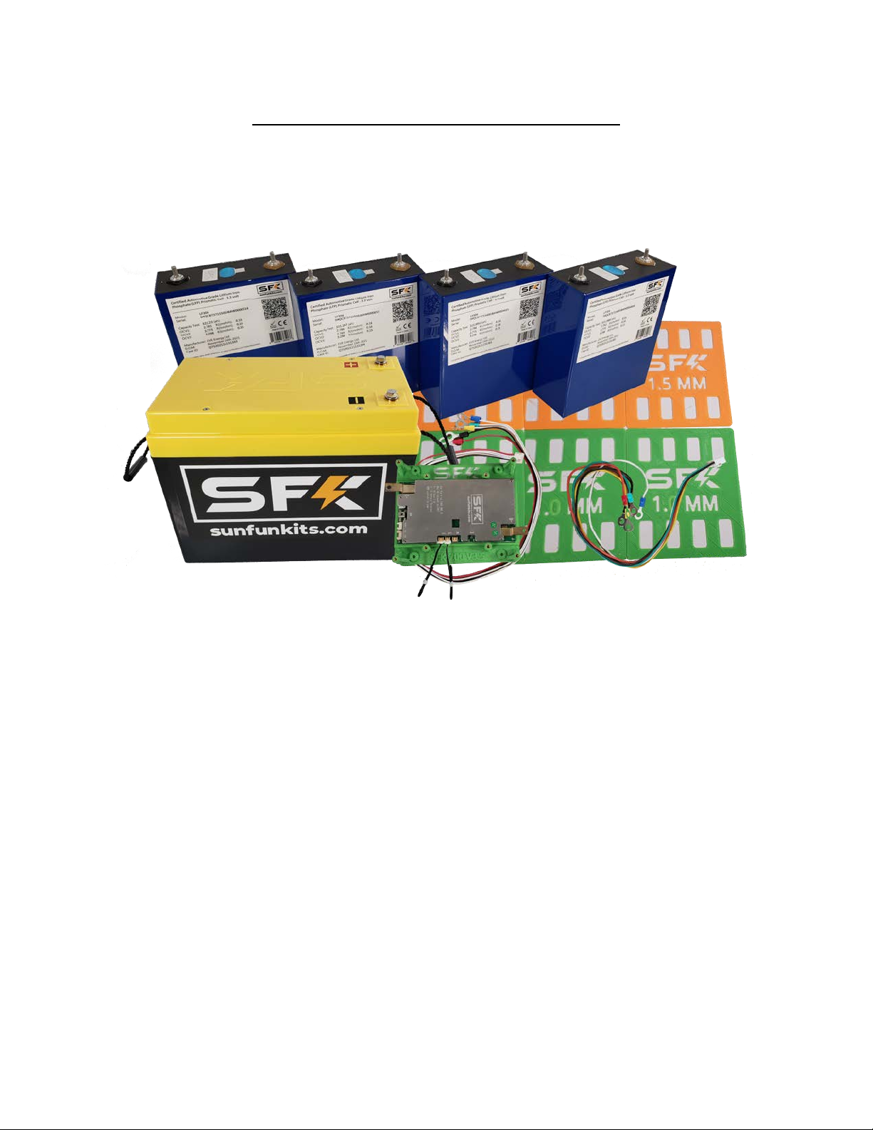
NOTE: if you are using an RTB (ready to build kit) the active balancer will assist in top balancing
your cells, simply assemble your pack, charge the battery at 5-20 amps and within 1-2 hours
your cells should be even balanced. Again, certified cells that are included with your RTB kit will
balance very quickly and the active balancer is included simply to assist balancing during high
amperage charging (over 80 amps).
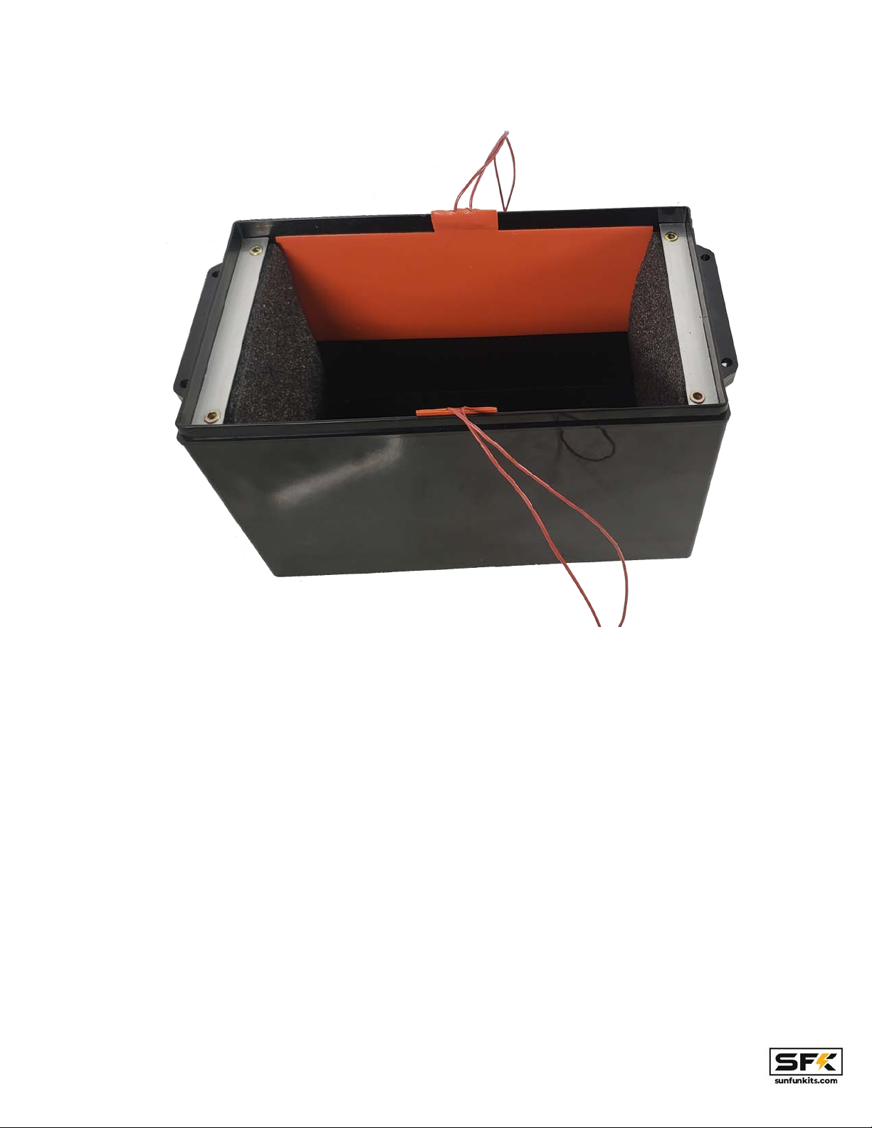
Assembling your battery cells:
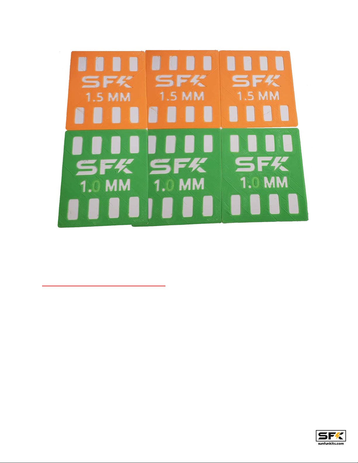
Starting with version 3.5 we are now including different cell shims or spacers, this allows users
to have a nice tight fit while also adding a third layer of insulation between cells. Version 3.5
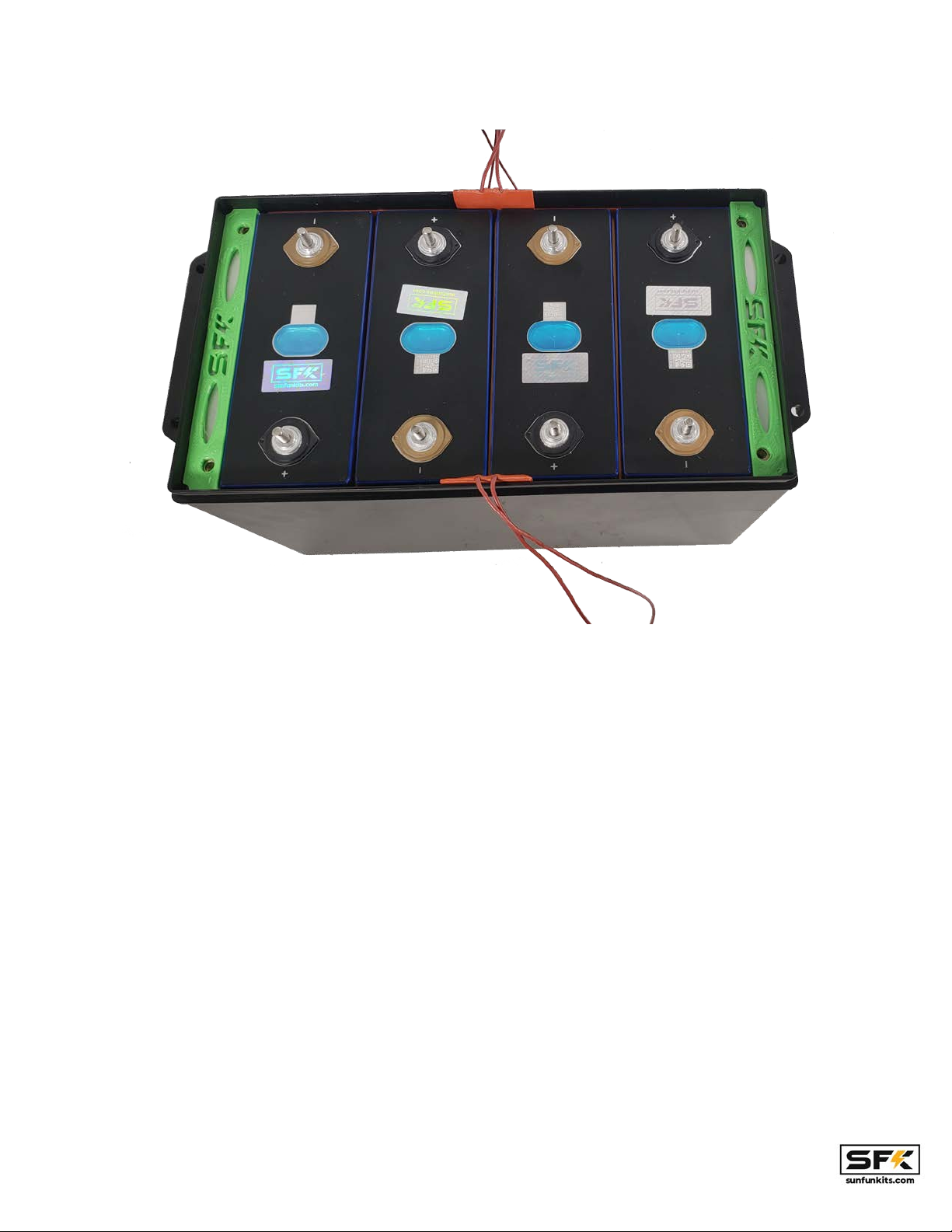
includes 1 set of 1.5mm and 1.0mm shims (3 pieces each). The shims should be placed
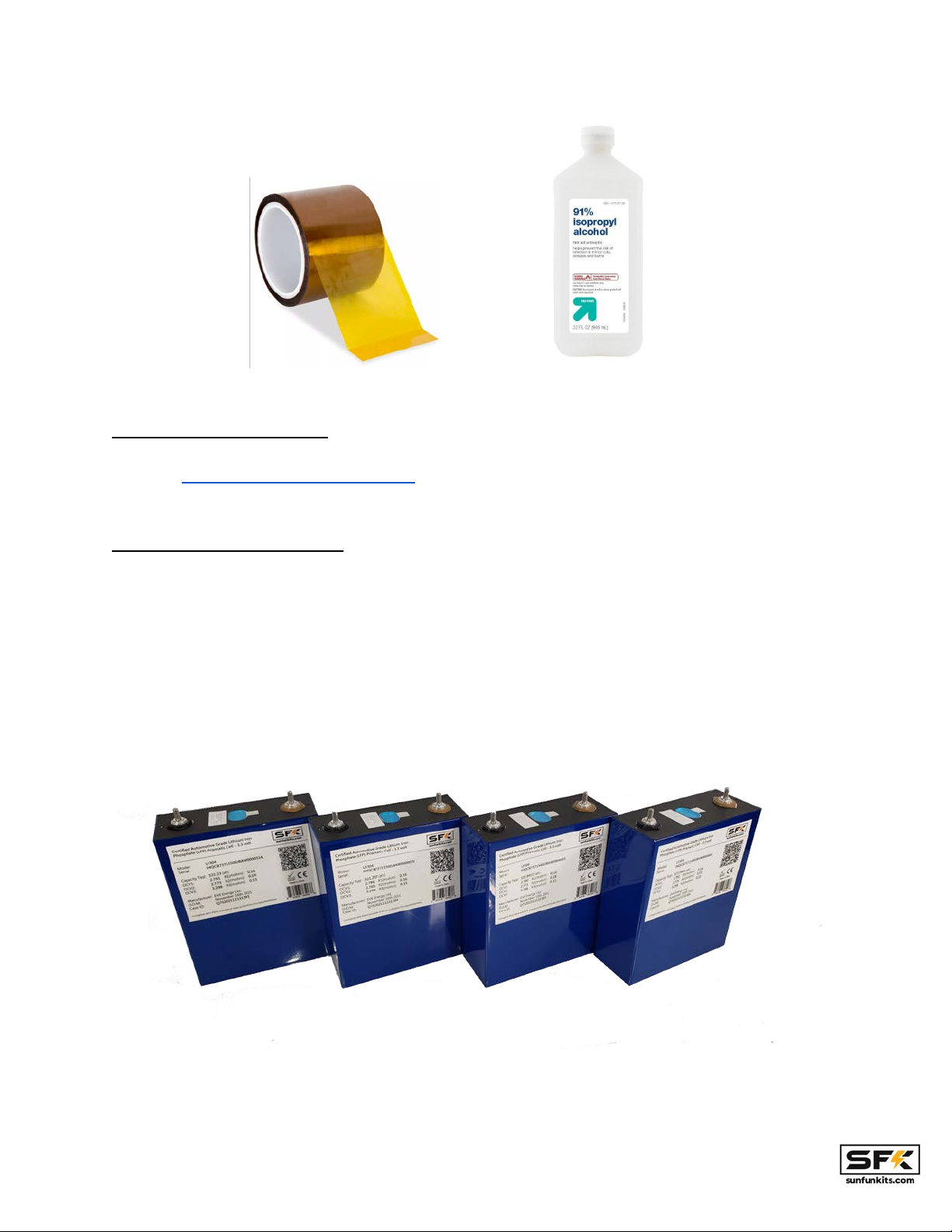
between the inner cells and most installs will use about 3 shims. For Sun Fun Kits certified cells
(280K and LF304) you should be able to use 3 x 1.5mm shims to complete the install and have
a nice tight fit.
Page: 4 V3.5 Manual - Revision 1.3

If you find difficulty installing the 1.5mm shims you may go down to 1.0 MM shims, you can mix
and match the 1.0 and 1.5mm shims as needed to suit your install preference.
OPTION1: Basic Heating Element Setup:
Version 3.5’s basic heating element includes dual heating pads on the inside walls of your kit.
This provides good heating and will raise the inside temperature of your case evenly. This
method is quite easy to install and is the only method that should be used if you are using grade
B cells or swollen cells as it provides the most amount of spacing for the cells.
Page: 5 V3.5 Manual - Revision 1.3

Begin by placing your cells in a series configuration with the left side of the battery having the
positive terminal on the lower left and the negative terminal on the lower right.
Page: 6 V3.5 Manual - Revision 1.3

Note: You will want to have the textured side of the shim facing the cell you installed, with the
smooth side facing the empty space. This will ensure the shim stays in place while you install
cells.
Page: 7 V3.5 Manual - Revision 1.3

For the last cell make sure the shim’s smooth side is facing the opening, in this case we will be
inserting cell no.2 and both sides of the shims will be smooth for an easy install.
Note: you may find some resistance installing your cells, this is because the EPE foam exerts
pressure on the cells to keep them in place; this is why we recommend adding the left most and
right most cells first and then adding the remaining 2 inner cells in the end as shown in the
illustrations above.
PLEASE MAKE SURE TO PLACE CELLS CORRECTLY IN THE ORDER ABOVE.
V3.5 kits support various cells and depending on your cell height you may or may not need cell
spacers. For LF280K and LF304 cells sold by Sun Fun Kits, you will use the 4mm spacer on top
of the aluminum braces to raise the height of the support so that it matches the cell. If you are
using EVE LF280N or other cells that are 200mm tall you can skip this step as the aluminum
bracket matches the height of your cells.
Page: 8 V3.5 Manual - Revision 1.3

The heated kits will provide additional resistance to cells when they are being installed,
however, there is still sufficient space to insert the cells. It is recommended that you do not
install fully charged cells as they will make the process challenging.
Page: 9 V3.5 Manual - Revision 1.3

Once your cells are in the correct position; it is now time to install your bottom bracket. With our
v3 kits we have made our cell bracket universal and it should fit virtually all cells in the 270-320
AH class.
Install the bottom bracket with the M5 bolts and washers, you can use power tools to assist in
this step. NOTE: Ensure the negative and positive signs on the plate match your cells.
Version 3.5 has a notch cut on the upper and lower middle to allow the wires from the rubber
heating elements which provide a channel for the wires into the main battery assembly.
OPTION2: Setting up heating using heated cell-separators (advanced):
The cell separator option is the more advanced heating option available in version 3.5 kits, this
allows 2 cells to be heated by a single silicon rubber heating element; 2 elements in total are
able to heat all 4 cells. The direct contact nature of this option means that the cells will heat up
faster so there is a potential of having a bigger delta in temperature between the cells and the
rest of the case. However, this method will provide for superior cell heating.
Page: 10 V3.5 Manual - Revision 1.3

Locate the 2 silicone rubber heating elements and attach them to your cells using KAPTON
TAPE or PET/Polyester high temp Tape. DO NOT USE SCOTCH™ or other forms of plastic
tape, KAPTON (PET or Polyester BASED) is required to handle the heat being generated by the
silicone pads.
Once attached you will be able to place this into your battery case (note in this case there are
no heating elements on the sides of the case walls).
As with the non-heated kits, place the leftmost and rightmost cell first, ensuring they have the
correct polarity before installing.
Page: 11 V3.5 Manual - Revision 1.3

For the inner 2 cells you will use a shim for one of the cells to provide the final cell separator for
the kit, you can select from either the 1.0m or the 1.5mm shim depending on how tight you want
your install to be (the tighter the better for most installations).
The textured side of the shim should be facing the cell while the smooth side should be
exposed.
Page: 12 V3.5 Manual - Revision 1.3

You will use the same method to install the final cell as in the non-heated kits and work the cell
in. Some resistance is normal as this will ensure a tight fit and make sure your cells do not move
around.
After completing you will 2 heating pads and 1 shim, now you can place the cells spacers
(shown above as the green pieces that sit on top of the aluminum brackets) and proceed with
mounting the V3.5 main plate (note the cell spacers are needed for cells that are 204mm or
taller, if you have 200mm tall cells you do no need to add the cell spacers on
Route the heated cell-separators through the dedicated slots on the v3.5 kit.
Page: 13 V3.5 Manual - Revision 1.3

You will now need to crimp connectors to the wires of your heating pads, to do this you will need
to crimp 1 wire from each pad together for the yellow terminal (this will go to the positive lug on
the case) and 1 wire from each pad to the black terminal (this will go to the heater port on the
BMS). DO NOT CRIMP BOTH wires of the same pad together it will not complete the
circuit. Which wires you chose does not matter as long as the wires being crimped are not from
the same pad.
Page: 14 V3.5 Manual - Revision 1.3

Setting Up Electronics & Cell wiring:
Note: Before beginning this step it is EXTREMELY IMPORTANT that you clean and wipe
down all of your bus bars, washers, terminals and battery post with 90% isopropyl
alcohol. Dirty terminals and connections will result in improper readings and poor
results.
Begin by placing your bus bars in the orientation shown below and then place a m6 washer on
top of the bus bars, this is needed to provide an even and stable base for your BMS terminals.
This step involves wiring up your cells, you will need a BMS system and optionally a
supplementary balancing device to complete this step. You will also need to have the
appropriate wiring done to complete the electrical setup. If you are using our SFK-200V2 4s
Bms, all wiring and prep has been done for you; simply bolt onto your components; no crimping
or cutting is necessary.
Page: 15 V3.5 Manual - Revision 1.3

The V3.5 kit system supports various BMS devices from manufacturers such as JBD (SFK
Series), Daly, Ant, QUCC, and more. New device support is being added constantly; if you need
a specific mounting plate made, simply contact Sun Fun Kits support at [email protected]
Page: 16 V3.5 Manual - Revision 1.3

Begin by aligning your buss bars as follows:
Page: 17 V3.5 Manual - Revision 1.3

Now you will add your series terminals and BMS balancing/monitoring wires as well as the
active balancer wires (NOTE the initial negative post; and the final positive post are shared
between both the active balancer & BMS, all other posts may be separate for each cell)
USE EXTREME CAUTION! THE BLUE WIRE SHOULD NOT TOUCH THE POSITIVE
TERMINAL OF THE FIRST CELL OR IT WILL ARC AND DESTROY THE CELL. You should
consider covering this terminal with kapton tape or other insulating material to ensure
that it can not short circuit the first cell.
NOTE: be sure to use the included washers for the BMS and Active balancer terminals. A
washer should be placed above each bus bar, and optionally above it. For version 3.5 we are
now including M8 Nylon Lock nuts as they provide excellent anti-vibration capabilities without
needing thread locking compound.
Please note your BMS wires should be routed to the positive terminal and the active balancer
wires should be routed to the negative terminal.
Page: 18 V3.5 Manual - Revision 1.3

Your cells should come with the bus bar, terminal studs or welded terminals. Tidy up your install
using electrical tape, zip ties, or velcro strips. Setup the wiring schematic as follows:
Note: CAUTION!!! In many prismatic cells the positive terminal is colored black and the
negative terminal is colored brown! Please double check your cells with a volt/multimeter
before continuing.
black wire = cell 1(black lug) negative (0.00 Volts)
1st white wire (green lug) = cell 1 positive /(3.3 Volts)
2nd white wire (yellow lug)= cell 2 positive /(6.6 Volts)
3rd white wire (blue lug) = cell 3 positive /(9.9 Volts)
red wire = cell 4 (red lug) positive (13.2 Volts)
*The 1st white wire is the wire that is right next to the black wire, the subsequent wires will be
white wire 2, and white wire 3.
The active balancer should be wired as follows we will be using the negative terminal post for
most of the cells for this harness:
black wire = cell 1 negative (0.00 Volts)
green wire = cell cell 2 negative (3.3 Volts)
yellow wire = cell 3 negative bus bar) (6.6 Volts)
white wire (with blue lug) = cell 4 negative bus bar) (9.9 Volts)
red wire = cell 4 positive (13.2 Volts)
You will need to ensure a tight fit, take care not to strip your battery terminals, if you are using a
torque wrench you will want to tighten down to 4-6 NM. WARNING! Loose terminals will cause
the cells & batteries to fail.
Page: 19 V3.5 Manual - Revision 1.3

With version 3.5 we have color coded the BMS wires to match the active balancer to assist in
installs, you can use this combination to ensure you have matching connections.
If you are using a supplementary balance, you should install this as well, you will need to share
the final negative and positive terminals of the battery for the bms and the supplementary
Page: 20 V3.5 Manual - Revision 1.3
This manual suits for next models
5
Other Sun Fun Kits Batteries Pack manuals
Popular Batteries Pack manuals by other brands

Soluna
Soluna 10K Pack HV installation manual

Power Stroke
Power Stroke PSL0BA181 manual

MasterForce
MasterForce 252-8017 Operator's manual

MRHANDSFREE
MRHANDSFREE Portable Power Charger Pure Edition user manual

Power Stroke
Power Stroke PSL0BA121 quick start guide

Tripp Lite
Tripp Lite BP240V120 Specification sheet