EAST PENN Deka SOLAR User manual

Renewable Energy
Technical Manual

System Design ................................................1
Battery Operation
Storage ............................................................1
Temperature ....................................................1
Depth of Discharge (DoD) ..............................1
Charging ..........................................................1
Inverter/Charge Controller Settings ................1
Bulk............................................................1
Absorption..................................................2
Float ..........................................................2
Equalize ....................................................2
Maintenance ....................................................3
Battery Location
Space ..............................................................3
Floor Preparation ............................................3
Battery Racking System ..................................3
Ventilation ........................................................3
Environment ....................................................3
Operating Equipment ......................................3
Series / Parallel Wiring ....................................3
Glossary............................................................5
APPENDI A
Renewable Energy Worksheet ........................6
APPENDI B
Example of Typical 3 Stage Charger ..............7
APPENDI C
Example of Depth of
Discharge vs. Freezing Point ..........................8
TABLE OF CONTENTS
PROPOSITION 65 WARNING: Battery posts,
terminals and related accessories contain lead and
lead compounds, chemicals known to the State of
California to cause cancer and reproductive harm.
Batteries also contain other chemicals known to the
State of California to cause cancer. WASH HANDS
AFTER HANDLING.

1
SYSTEM DESIGN
Systems Design is the process of defining the architecture,
components, modules, interfaces, and load data for a system
to satisfy specified requirements. For a solar system these
components are the PV modules, inverter/charge controller
& batteries, as well as the different interfaces of those
components.
To properly size a battery/battery bank for a renewable energy
system the following parameters are required:
Load – Amount of DC current (Amps, Ah) or power (Watts,
Wh) a battery is required to supply to a DC load, AC load or
both through an inverter.
Time – expressed in hours the battery will be required to
provide the load.
System Voltage – DC system operating voltage
Ambient Temperature – Average temperature of battery
room or enclosure.
Depth of Discharge (DoD) – The proportion of energy that
has been removed from a battery; typically in a 24hr period
Example: 100% DoD is removing all
of the energy from a battery.
Autonomy – Length of time, typically in days the PV battery
bank can provide energy to load without energy from PV
array, generator, grid, etc…
Design Margin - Factor (typically expressed as a percentage)
to allow for future load additions.
A Renewable Energy Worksheet is provided in Appendix A
listing the above requirements along with additional information
requirements
BATTERY OPERATION
There are several factors that affect the operation of the battery
concerning its ability to deliver capacity and life expectancy.
Storage
Cells should be stored indoors in a clean, level, dry, cool
location. Recommended storage temperature is 0°F to 90°F
(–18°C to 32°C).
Consult specific battery Installation & Operating manuals for
time interval & boosting requirements.
Temperature
Many chemical reactions are effected by temperature, and
this is true of the reaction that occurs in a storage battery.
The chemical reaction of a lead-acid battery is slowed down
by a lowering of the electrolyte temperature that results in
less capacity. A battery that will deliver 100% of rated
capacity at 77° F will only deliver approximately 65% of
rated capacity at 32°F.
At temperatures below 32°F (0°C) a battery can freeze depend-
ent on the DoD (Depth of Discharge). The higher the DoD, the
closer to 32°F (0°C) before the battery will freeze. The graph in
Appendix C should be consulted to verify the DoD of the bat-
tery / battery bank at the end of the discharge will not be sus-
ceptible to freezing in a particular application. If the electrolyte
would freeze, the internal damage would be irreversible requir-
ing the battery to be replaced.
Depth of Discharge (DoD)
Depth of discharge is a function of design. The deeper the
discharge per cycle, the shorter the life of the battery. A cycle
is a discharge and its subsequent recharge regardless of
depth of discharge.
Systems should be designed for shallow discharges. The
result of shallower discharges is typically a larger capacity
battery at prolonged battery life.
A Cycle vs. DoD chart should be consulted to determine
the number of cycles at a specific DoD and the projected life
in years the battery / battery system will provide prior to
needing replacement.
Charging
Majority of battery capacity/life issues can be traced to
improper charging. Improper charging settings may lead to
an overcharging or undercharging condition.
Typical Inverters/Charge Controllers charging lead-acid
batteries use 3 stage charging: Bulk, Absorption and Float
with an optional equalize stage. See Appendix B for an
example of a typical 3-stage charging curve.
Inverter/Charge Controller Settings
Proper Inverter/Charge Controller settings are necessary
to ensure peak battery performance and life. All bulk,
absorption, float and equalize settings should be verified they
are within the battery manufacturers settings. These settings
are included but not limited to; voltage, current and time.
Consult individual battery Installation & Operating manuals
for inverter/charge controller setting recommendations.
Default settings should not be presumed to be correct.
For battery systems located in an uncontrolled temperature
environment, temperature compensation must be used.
Bulk
Current is applied to the batteries at the maximum safe rate
they will accept until voltage rises to near (80-85%) full charge
level. The battery voltage rises because the charging current
that is provided by the battery charger is replenishing its
Renewable Energy applications that depend on battery power as part of the system operation must be at
maximum performance at all times. To ensure this high rate of performance is achieved, the battery charging
system must be set properly. A battery/battery bank that is undercharged or overcharged will affect the
battery system performance & life, as well as the performance of the entire system.
ey factors that affect a batteries ability to provide the capacity and long life that is expected are: System
Design, Storage, Temperature, Depth of Discharge (DoD), Charging and Maintenance.

2
Bulk continued
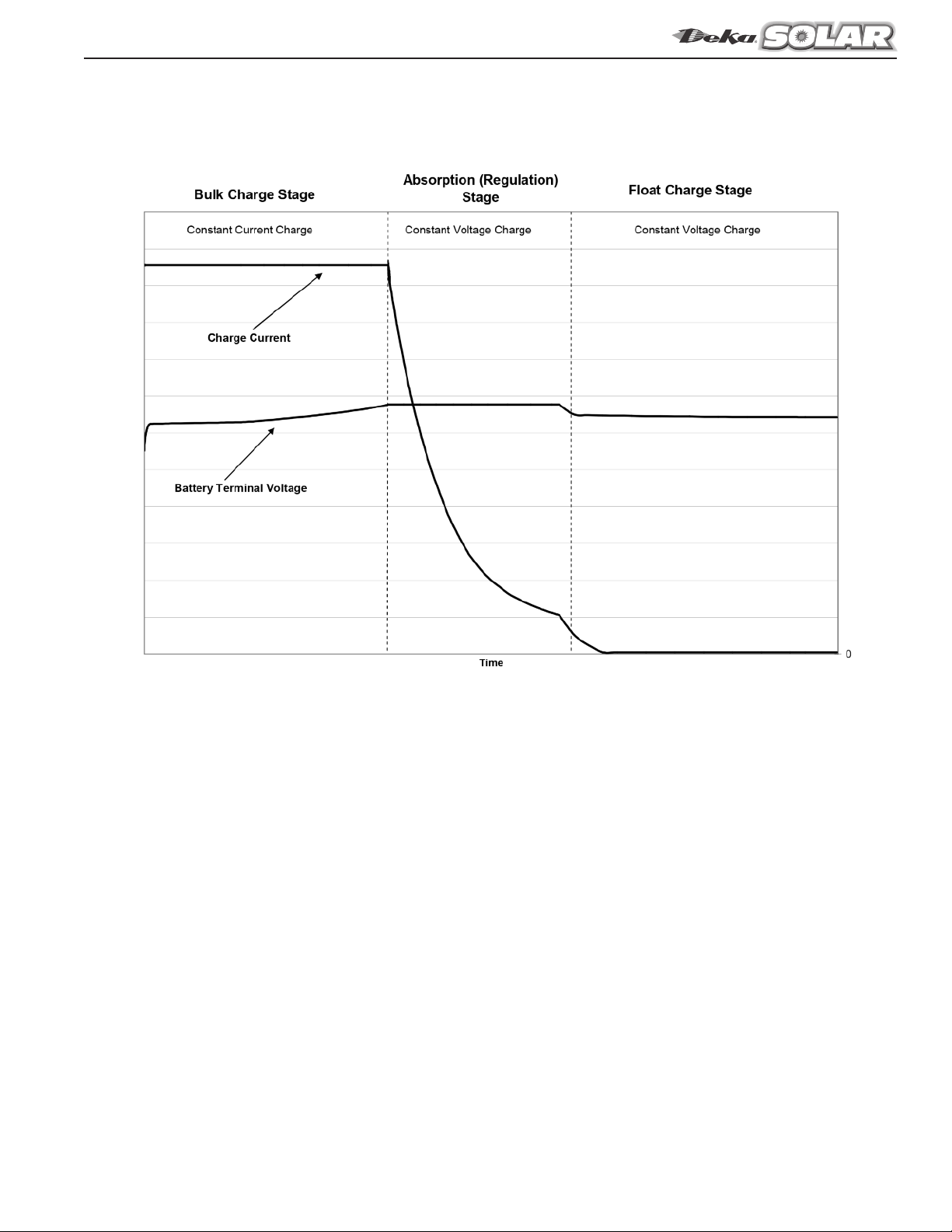
internal charge capacity. The charger current is flat (constant)
and the battery voltage is rising.
Maximum allowable charge voltage & current allowed by
the battery manufacturer should be used to ensure the most
energy is returned within the bulk stage.
Bulk Charge Stage Time Calculation:
Max Time (Hr) = (Ahr x 1.2)/Avg. Current (A)
Ahr = Amp hours removed during discharge.
1.2 = Recharge multiplier
Avg. Current = Average current available
to battery from charger.
Note: Avg. current should be < maximum current limits
for installed battery. Charge current limits available
from your East Penn representative.
Max Time (Hr) – Maximum charge time for battery to
reach 80% - 85% state of charge
Absorption
The charger will attempt to hold its output voltage constant
while the battery continues to absorb charge (draw charging
current) from the charger. The rate at which the battery con-
tinues to absorb charge in this mode gradually slows down.
The amplitude of the charger current is gradually decreasing.
The charge current is falling and the battery voltage is flat
(constant).
Some Inverter/Charge Controllers can either use time or
current to determine the length of the absorption stage.
Time regulated absorption is based on a predetermined time
after the battery has completed the bulk stage (charge voltage
has reached its maximum set point). A lead-acid battery is said
to be at 80% to 85% SOC (State of Charge) when the voltage
set point is met and the current starts to taper; considered the
start of absorption. The remaining time required to reach
100% SOC is based on ever changing factors: solar isolation
(summer vs. winter), ambient temperature, battery type
(flooded, VRLA), and battery age.
Absorption stage time should be set to optimize the available
sun hours during the winter and/or cloudy months. If improp-
erly set, there is a risk of undercharging the battery system.
It is recommended to set the absorption time to the maxi-
mum time setting possible to take advantage of all available
charging light regardless of time of year or weather issues.
Using this method, the sun availability will determine the
absorption time. Following this recommendation, there is no
risk of overcharging if the battery charge voltage is set within
the recommended settings.
The amount of available power (current) to the batteries is
important for getting a battery charged. Available power
(current) to the batteries is the remaining power (current) after
connected loads are satisfied. Maximum charge voltage and
current allowed by the battery manufacturer should be used to
ensure the most energy is returned to the batteries.
The below calculation will assist in identifying the necessary
maximum charge current for the system. If the calculation
shows the absorption time is greater than the minimum
average peak sun hours for the installation location, the
amount of available current to the batteries should be
increased, which could be accomplished by a larger array
or a secondary power source such as a generator.
Charge Current Verification:
FLOODED
C20 x 0.44/charge current available
Example:
Maximum Charge Current
Battery Rating: 1186Ah (C20)
237A – Charge current (maximum)
1186Ah x 0.44 / 237 = 2.20 hrs
Minimum Charge Current
Battery Rating: 1186Ah (C20)
118A – Charge Current (minimum)
1186Ah x 0.44 / 118A = 4.42 hrs
VRLA (AGM & GEL)
C20 x 0.39/charge current available
Example:
Maximum Charge Current
Battery Rating: 183Ah (C20)
55A – Charge current (maximum)
183Ah x 0.39 / 55A = 1.30 hrs
Minimum Charge Current
Battery Rating: 183Ah (C20)
18.3A – Charge Current (minimum)
183Ah x 0.39 / 18.3A = 3.90 hrs
Current regulated absorption is using the charge current
to determine battery state of charge, which eliminates a
majority of the variables previously mentioned with time
based absorption (solar isolation, ambient temperature,
battery type). Charging in constant voltage, when a
battery/battery system reaches the absorption voltage setting
the current will start to taper. The point at which the current
stops tapering or declining is referred to as the stabilizing
current. This is an indication that the battery is fully charged
and the current the battery/battery system is drawing is only
needed to keep the battery at the set voltage. This minimum
or stabilizing current will change based on the charge voltage
setting. Battery manufacturer should be consulted for current
settings.
An additional option for determining the SOC of a battery is
monitoring the Ah (amp hour) removed from a battery
during a discharge and the amount of Ah returned during
charge; similar to a gas gauge in a car. The Ah in and out
should be monitored on a continuous basis to keep track of
the overall SOC not just from day to day.
Float
The voltage at which the battery is maintained after being
charged to 100% SOC (State of Charge) to maintain capacity
by compensating for self-discharge of the battery.
Equalize
A charge, at a level higher than the normal float voltage,
applied for a limited period of time, to correct inequalities of
voltage, specific gravity, or state of charge that may have
developed between the cells during service.
Note: Equalize charging not required on VRLA (AGM/Gel)
as part of a daily charge setup. Based on PV applications,
unpredictable recharge availability, periodic equalize may
be required.

3
Equalize continued
Consult individual Installation & perating Manuals for
details on Inverter/Charger Controller settings to properly
charge East Penn lead-acid batteries. A voltage range is
provided because of equipment setting availability/limita-
tions, however for optimal charge performance all setting
should be at the highest setting of the battery range that
the inverter/charge controller can handle.
Maintenance
IEEE (Institute of Electrical and Electronics Engineers) suggests
batteries be checked on a monthly, quarterly and yearly basis.
Each time period requires different checks. A maintenance log
should be initiated at the time of installation.
Typical checks consist of voltage, specific gravity (not
required for VRLA) and visual inspections. Periodic verifica-
tion of voltages will ensure battery is being fully charged and
operating properly. If any conditions are found that are out of
specifications, corrections should be made.
A good battery maintenance program is necessary to protect
life expectancy and capacity of the battery. Reference IEEE
450 for Flooded batteries and IEEE 1188 for VRLA (Valve
Regulated Lead-Acid) batteries.
BATTERY LOCATION
When planning a battery system the following requirements
should be considered:
• Space
• Floor Preparation
• Battery Racking System
• Ventilation
• Environment
• perating Equipment
Space
It is recommended that aisle space be provided in front of all
battery racks be a minimum of 36.0” (915mm). The design
should meet all applicable local, state and federal codes and
regulations.
Floor Preparation
It is recommended to consult with a structural engineer to
determine if the existing floor will withstand the weight of the
battery and the battery racking system. The floors in which the
battery will be located should have an acid-resistant coating.
Any battery spills should be neutralized with non-corrosive,
water based neutralizing chemical (ex: baking soda/water
solution) that is user safe and environmentally compliant.
The area should always be washed with clean water to remove
any acid neutralizing chemical residue.
Battery Racking System
The battery should not be installed directly on a floor. There
should be some type of barrier/racking between the floor and
the batteries. This barrier/racking should be sufficient to handle
the weight of the battery. The battery racking system must be
suitably insulated to prevent sparking and eliminate any
grounding paths.
Adequate space and accessibility for taking individual battery or
cell voltage, hydrometer readings and adding water should be
considered. If installed in an earthquake seismic zone, battery
racking system must be of sufficient strength and adequately
anchored to the floor. Battery rack design and anchoring should
be reviewed by a structural engineer.
Ventilation
It is the responsibility of the installer to provide detailed
methods or engineering design required by Federal, State
and local regulations to maintain safe levels of hydrogen in
battery rooms/enclosures.
The rate of hydrogen evolution is highest when the battery is
on charge. Explosive mixtures of hydrogen in air are present
when the hydrogen concentration is greater than or equal to
4% by volume. To provide a margin of safety, battery
room/enclosure must be ventilated to limit the accumulation of
hydrogen gas under all anticipated conditions. This margin of
safety is regulated by Federal, State and Local codes and is
typically limited to 1% to 2% by volume of the battery
room/enclosure.
Consult all applicable codes to determine specific margin of
safety. Hydrogen gas calculations can be determined by using
proper formulas.
Hydrogen gas is lighter than air and will accumulate, creating
pockets of gas in the ceiling. The ventilation system should be
designed to account for and eliminate this situation. Ventilation
system must be designed to vent to the outside atmosphere by
either natural or mechanical means in order to eliminate the
hydrogen from the battery room/enclosure.
Environment
Batteries should be located in a clean, cool and dry place and
isolated from outside elements. The selected area should be free
of any water, oil and dirt from accumulating on the batteries.
Operating Equipment
Battery systems are sized based on a specific load (Amps
or Watts) for a specific run time to a specific end voltage.
Battery performance is based on these values, as measured
at the battery terminals.
For proper operation of the battery system the following should
be considered:
• Distance between battery system and operating systems
should be kept at the shortest distant possible.
• Cables are to be of proper gauge to handle system loads
and minimize voltage drops.
• All cable lengths from battery system to operating system
should be of the same wire gauge and length.
The above is to ensure the battery cable used will be able to
carry the charge/discharge current & minimize the voltage drop
between equipment.
Electrical equipment should not be installed above the batteries,
because of the possibility of corrosive fumes being released
from the battery(s).
Series/Parallel Wiring
Series and parallel wiring of batteries as well as battery
to inverter/charge controller wiring should be designed to
minimize voltage drop. Wire gauge, wire length as well as
interbattery connection layout are all variables in reducing
voltage drop as well as providing battery balance between
parallel battery strings.
Proceeding are examples of common wiring layouts with
narrative of the advantages and / or disadvantages of each.

4
Series/Parallel Wiring continued
Daisy chain wiring
A wiring scheme in which multiple devices are wired togeth-
er in sequence. All interconnecting wiring should be of same
length to minimize voltage drop.
Disavantages:
• The interunit cables are required to increase in gauge
size to accommodate the increase in current of each
connected string.
• Maintenance and battery diagnostics require the entire
battery system to be disconnected from the renewable
energy system, leaving no back up energy source.
• Wiring connection assessment difficult to follow with
multiple wirings connected to same battery terminal,
increasing chance of re-connection wiring errors.
Common bus wiring
A wiring scheme in which same polarity terminals are con-
nected to a single termination point. All interconnecting
wiring should be of same length to minimize voltage drop.
Advantages:
• Cables can be of same gauge.
• Maintenance and battery diagnostics can be performed
on a single string while maintaining a level of back up
energy source from the other strings staying connected
to the renewable energy system.
• Wiring connection assessment simplified by single point
cabling reducing re-connection wiring errors.

5
GLOSSARY:
AGM – Absorbed Glass Mat – A class of VRLA (Valve
Regulated Lead-Acid) battery in which the electrolyte is
absorbed into a glass mat.
Ambient Temperature – The average temperature of the
battery room. Temperatures below 77°F (25°C) will reduce
battery capacity. Temperatures above 77°F (25°C) will
reduce battery service life.
Amp Hour (Ah) – Amps times Hours
Battery Efficiency – The amount of Ah return required
to achieve full SOC vs. the amount of Ah removed during
discharge. Require 110% to 115% Ah return.
Capacity – The capacity of a battery is specified as the
number of Amp-Hrs that the battery will deliver at a specific
discharge rate and temperature. The capacity of a battery is
not a constant value and is seen to decrease with increasing
discharge rate.
C20 – Battery capacity measured in Ah (amp hour) at the
20hr rate.
End Voltage – The minimum voltage at which a DC system
will operate.
Flooded – A battery in which the products of electrolysis
and evaporation are allowed to escape to the atmosphere
as they are generated. Electrolyte is free flowing throughout
the battery.
Gel – A class of VRLA (Valve Regulated Leda-Acid) battery
in which the electrolyte is immobilized in a gel form (sulfuric
acid mixed with silica).
Parallel – A circuit that provides more than one path for the
flow of current. A parallel arrangement of batteries (usually
of like voltages and capacities) has all positive terminals
connected to a conductor and all negative terminals con-
nected to another conductor. If two 12-volt batteries of 50
ampere-hour capacity each are connected in parallel, the
circuit voltage is 12 volts, and the ampere-hour capacity of
the combination is 100 ampere-hours.
Series – A circuit that has only one path for the flow of
current. Batteries arranged in series are connected with
negative of the first to positive of the second, negative of the
second to positive of the third, etc. If two 12-volt batteries
of 50 ampere hours capacity each are connected in series,
the circuit voltage is equal to the sum of the two battery
voltages, or 24 volts, and the ampere-hour capacity of the
combination is 50 ampere-hours.
S C (State of Charge) – The amount of deliverable
low-rate electrical energy stored in a battery at a given time
expressed as a percentage of the energy when fully charged
and measured under the same discharge conditions. If the
battery is fully charged the “SOC” is said to be 100%.
Temperature Correction – A factor used to compensate for
battery capacity and/or adjust battery voltage at ambient
temperatures greater than or less than 77°F (25°C).
Undercharge (Deficit charge) – Charging a battery with less
ampere-hours (Ah) than is required to return the battery to
its initial state-of-charge. This results in a reduction in the
battery state-of-charge.
VPC – Volts per Cell
VRLA – Valve Regulated Lead Acid – a lead-acid cell/battery
that is sealed with exception of a valve that opens to the
atmosphere when the internal gas pressure exceeds atmos-
pheric pressure by a pre-selected amount. VRLA batteries
provide a means for recombination of internally generated
oxygen and the suppression of hydrogen gas evolution to
limit water consumption.

6
APPENDIX A
Completing all parameters ensures accurate battery sizing.
Worksheet to be submitted to sales representative for battery recommendation.

7
APPENDIX B
Example of typical 3 stage charger

UL Recognized Component
E.P.M. Form No. 2520 2/20 © 2020 by EPM Printed in .S.A.
All data subject to
change without notice.
No part of this document may
be copied or reproduced,
electronically or mechanically,
without written permission
from the company.
Domestic Inquiries Call: 1-800-372-9253
www.mkbattery.com • e-mail: sales@mkbattery.com
East Penn Man fact ring Co.,
Lyon Station, PA 19536-0147
Domestic & International Inq iries Call: 610-682-3263
Phone: 610-682-6361 • Fax: 610-682-0891
www.dekabatteries.com • e-mail: reservepowersales@dekabatteries.com
APPENDIX C
Below graph is for general reference only. Consult specific battery Installation & Operating Manual for applicable graph.
Table of contents
Other EAST PENN Batteries Pack manuals