Del Morino Funny User manual
Funny-e-18 Use and maintenance manual : Funny
Del Morino srl , v.Caroni di Sotto 19,
I-52033 Caprese Michelangelo AR Italy
Ph: +39-575-791059 Fax: +39-575-791210
E.mail: export@del-morino.it
http://www.del-morino.it
USE AND MAINTENANCE MANUAL
LIGHT SLASHER TYPE FUNNY

2
PREFACE
This manual is an integral part of the machine.
It must always accompany the machine and be kept within reach of the operator.
The enclosures mentioned are on integral part of this manual.
The purpose of this manual.
This manual gives information for the correct and safe use of the machine.
The owner must read this manual carefully before work with the machine.
Responsibility of the owner
The owner is responsible for accidents or damages caused to people or things due to negligence in following
the instructions in this manual.
Assistance in using this manual
Explanations: contact the dealer.
Request for additional copies of the manual: in case of loss or wear and tear, or in case one wants the
manual in a different language, the customer should ask the dealer or manufacturer.
Pay attention to the warning signals
<Danger>: indicates a situation that is potentially dangerous which, if not avoided, will cause death or
serious damage.
<Warning>: indicates a situation that is potentially dangerous which, if not avoided, will cause death
or serious damage.
<Caution>: indicates a situation that is potentially dangerous which, if not avoided, can cause minor to
moderate damage, or it indicates to be careful about an unsafe procedure.
<Important> : indicates instructions that must be followed precisely in order to avoid damage to the product,
process
or environment.
<Note>: indicates supplementary information.

3
DESCRIPTION
FUNCTION OF USE
The machine according to the different tools can makes different functions like cut grass, cut up poles exc.
The use of a technical constructive concept trended to the search of high performances, reduction of trebles
and durability, improves the power/consumption ratio of the tractor thanks to the elasticity of the machine
frame, to the tools shape, to the perfect rotor balancing and to many original technical solutions.
PERFORMANCES
The machine is connected to the tractor with a three points hitch that gives the motion of translation and with
a PTO shaft connected with the tractor PTO that gives the motion of rotation to the hoes shaft.
The working width is fix and it's determined from the choice of the machine type.
The working depth is adjustable.
The working zone is centered with tractor axis.
The rear roll adjusts the cutting height and provides to tread the cut material.
PERFORMANCES LIMIT
Speeds greater than the maximum can compromise the condition of the machine, the quality of the work
and the safety of the operator.
Maximum power applicable to the gear box: from 9 to 20 Kw 5% with 540 r.p.m. Superior power to
which is indicated can damage irreparably the transmission gear box; especially during heavy works.
STANDARD EQUIPMENTS
-Standard PTO shaft.
-Free wheel device inside gear box.
-Rear roll.
-Blade tools
VARIANTS & OPTIONS
-Spatula tools
-Hammer tools

4
TECHNICAL SPECIFICATIONS
CHARATTERISTICS PER MODEL
Model Typo Version Power Working
width Weight Dimensions
A x B x H Tools
nr Rotor
RPM
Hp Kw cm Inch kg lbs Cm n° g/min
FUNNY
80 S 12-28 9-20 80 32 105 231 94x60x60 12 2410
80 TS 12-28 9-20 80 32 105 231 94x60x60 12 2410
93 S 12-28 9-20 93 36 110 242 107x60x60 16 2410
93 TS 12-28 9-20 93 36 110 242 107x60x60 16 2410
106 S 12-28 9-20 106 42 122 269 120x60x60 16 2410
106 TS 12-28 9-20 106 42 122 269 120x60x60 16 2410
132 S 12-28 9-20 132 52 138 304 146x60x60 20 2410
132 TS 12-28 9-20 132 52 138 304 146x60x60 20 2410
158 S 12-28 9-20 158 62 160 353 172x60x60 24 2410
158 TS 12-28 9-20 158 62 160 353 172x60x60 24 2410
FUNNY
80 C 12-28 9-20 80 32 105 231 94x60x60 24 2410
80 TC 12-28 9-20 80 32 105 231 94x60x60 24 2410
93 C 12-28 9-20 93 36 110 242 107x60x60 16 2410
93 TC 12-28 9-20 93 36 110 242 107x60x60 16 2410
106 C 12-28 9-20 106 42 122 269 120x60x60 32 2410
106 TC 12-28 9-20 106 42 122 269 120x60x60 16 2410
132 C 12-28 9-20 132 52 138 304 146x60x60 40 2410
132 TC 12-28 9-20 132 52 138 304 146x60x60 40 2410
158 C 12-28 9-20 158 62 160 353 172x60x60 48 2410
158 TC 12-28 9-20 158 62 160 353 172x60x60 48 2410
FUNNY
80 M 12-28 9-20 80 32 105 231 94x60x60 24 2410
80 TM 12-28 9-20 80 32 105 231 94x60x60 24 2410
93 M 12-28 9-20 93 36 110 242 107x60x60 16 2410
93 TM 12-28 9-20 93 36 110 242 107x60x60 16 2410
106 M 12-28 9-20 106 42 122 269 120x60x60 32 2410
106 TM 12-28 9-20 106 42 122 269 120x60x60 16 2410
132 M 12-28 9-20 132 52 138 304 146x60x60 40 2410
132 TM 12-28 9-20 132 52 138 304 146x60x60 40 2410
158 M 12-28 9-20 158 62 160 353 172x60x60 48 2410
158 TM 12-28 9-20 158 62 160 353 172x60x60 48 2410
Version:
C = Blade
S = Spatula
M= Hammer
TC = Shiftable-Blade
TS = Shiftable-Spatula
TM= Shiftable-Hammer

5
SAFETY INFORMATIONS
PRESCRIZIONI GENERALI
Only work in daylight.
To prevent damage due to lunch of objects or parts of blades, before to start job be sure that any persons
or animals should be in the radius of 50 meters from the machine.
Wear long pants and heavy shoes.
The protections are integral part of the machine: always work with the protections.
Pay attention to the soil: make sure that are not stones, sticks, iron wires, etc…
Pay attention using the machine on slopes: proceed to the maximum slope and never work in slanting
direction.
Before leaving the driver's seat, turn off the engine and disengage the transmission engine-shaft.
Check immediately the machine if it touches foreign objects.
Check immediately the machine if there are unusual strong vibrations.
Change quickly defective parts.
CAUTION – WARNING :
Gear box has inside a free wheel device, after P.T.O. disconnection rotor turns for at
least 30 seconds, before approach the tools be sure that the rotor is stopped.
WARNING :
To prevent damage to the PTO shaft and to the gear box, don’t start the machine
roughly.
SAFETY RESTRICTIONS
Children and people who are not familiar with these instructions must not be permitted to use the machine.
Local regulations can restrict the use of the machine in accordance to the age.
RUNNING IN
A new machine needs a running in. At the first use connect the machine to the tractor, connect the PTO shaft,
pull down the machine at 15 centimeter from ground then start the P.T.O. and gradually bring it to 540 r.p.m...
Run the machine for about 15 minutes. A whistle in the supports zone it is normal and it’s due to the
arrangement of the support protection, it will disappear in a few times.
6
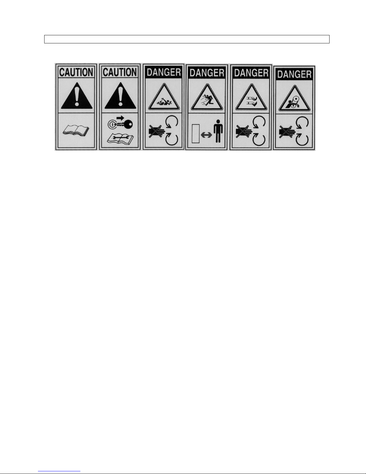
SAFETY SIGNS ON THE MACHINE
In this section, the safety signs on the machine are reproduced and explained.
1 2 3 4 5 6
1. Read the operator manual.
2. Disconnect the tractor key before maintenance and repair operations.
3. Stay at safety distance from blades when machine is moving.
1. Danger of flying objects. Stay at safety distance.
4. Stay at safety distance from blades when machine is moving.
5. Stay at safety distance from blades when machine is moving.
The safety signs on the machine must always be legible.
In case of damage, the labels of the signs must be substituted.
In the case of the substitution of machine parts that have safety signs, the signs must be replaced.
Supplying of new safety labels and the application procedure
Contact your dealer to receive new safety labels with instructions for application.

7
INSTRUCTIONS FOR USE
1. BEFORE BEGINNING WORK
a) Hook the machine to the tractor, operate as follows :
1. Remove the safety pins from the two lower connection points of the machine.
2. Plug in the raising tractor beams into the lower connection points of the machine and lock with the
safety pins.
3. Connect through tie-rod the third hitch point of the tractor with the third point of the machine (the
connection triangle vertex), insert the pin and lock with safety pin.
b) With the machine raised, go to work area.
c) Connect the tractor PTO with machine PTO.
d) Check that PTO chain is locked to prevent the protection sheet of PTO rotating.
e) Adjust the cutting height as follow :
1. Pull down the machine since the rear roll touches the ground.
2. Extend the III° point tie rod to increase the cutting height, shorten it to decrease.
3. After the regulation, lock the safety not of the tie rod.
2. TO BEGINNING WORK
a) Keep people and animals at least 65 feet radius all around the machine.
b) Pull down the machine until the hoes touch the ground.
c) Connect PTO power and gradually bring it to 540 r.p.m...
d) Pull down completely the machine and start to work.
3. AT THE END OF CUTTING OPERATION
a) Stop the tractor and wait at least 30 seconds that the rotor is completely stopped.
b) Raise the machine until the hoes goes out from ground.
c) Disconnect PTO power.
d) Disconnect tractor PTO from machine PTO.
e) Raise completely the machine.

8
MAINTENANCE INSTRUCTIONS
On diagram "A" the maintenances are indicated with their terms to effect on the machine.
Not follow the scheduled terms can compromise the functionality of the machine and in this case the warranty is
not applicable.
DIAGRAM “A” SCHEDULED MAINTENANCE
FIRST
START AFTER
10 H. EACH
30 H. EACH
500 H. END
SEASON START
WORK END
WORK
MACHINE Greasing Greasing Cleaning
Greasing Cleaning
GEAR BOX Oil level Oil level Oil level Change oil
SCREW Screw Screw
TOOLS Check Check Check Check
BELTS Check Replacement
9
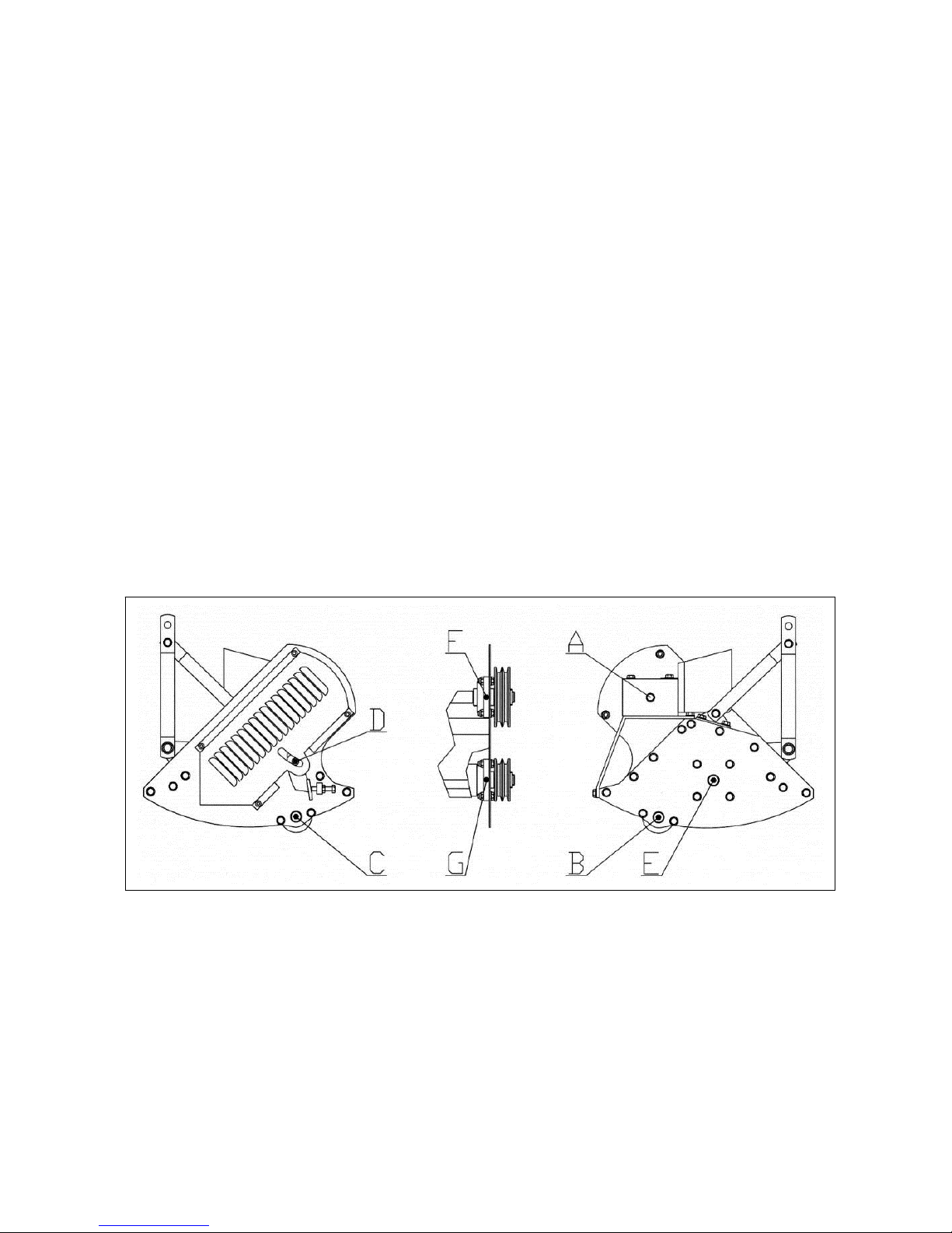
1. GREASING
At the scheduled time on diagram "A", grease points "B" “C”, “D”,”E”, “F”, “G”.
Greasing point is equipped with greaser HYDRAULIC TYPE MODEL "A" UNI 7663.
To greasing use only MULTIFUNCTIONAL GREASE LITHIUM BASED Type NLGI 2.
2. OIL CHECK - OIL REPLACEMENT IN GEAR BOX
At the scheduled time on diagram "A", check or replace oil into gear box.
To fill oil use only OIL SAE 140 EP.
Gear box capacity: 0,8 L
a) To check oil level into the gear box, operate as follow :
1. With the machine on level unscrew plug "A" then check that oil touches on lower hole rim.
2. If the level is ok, screw plug "A".
3. If the level is slow, refill.
4. When the level is ok, screw plug "A".
b) To change oil into the gear box, operate as follow :
1. Unscrew plug "A" and take away oil using a suitable little pump.
2. Fill oil from plug "A".
3. When level is ok, screw plug “A”.
10
3. TOOLS REPLACEMENT
a) To change tools, operate as follow :
1. Unscrew the nut then take out the screw “B”.
2. Take out tools “A” with bushes.
3. Assemble the new tool.
4. Fit the screw “B” then screw the nut.
5. ATTENTION: all tools must be of the same type.
6. ATTENTION: changing type of tools you must balance again the rotor.
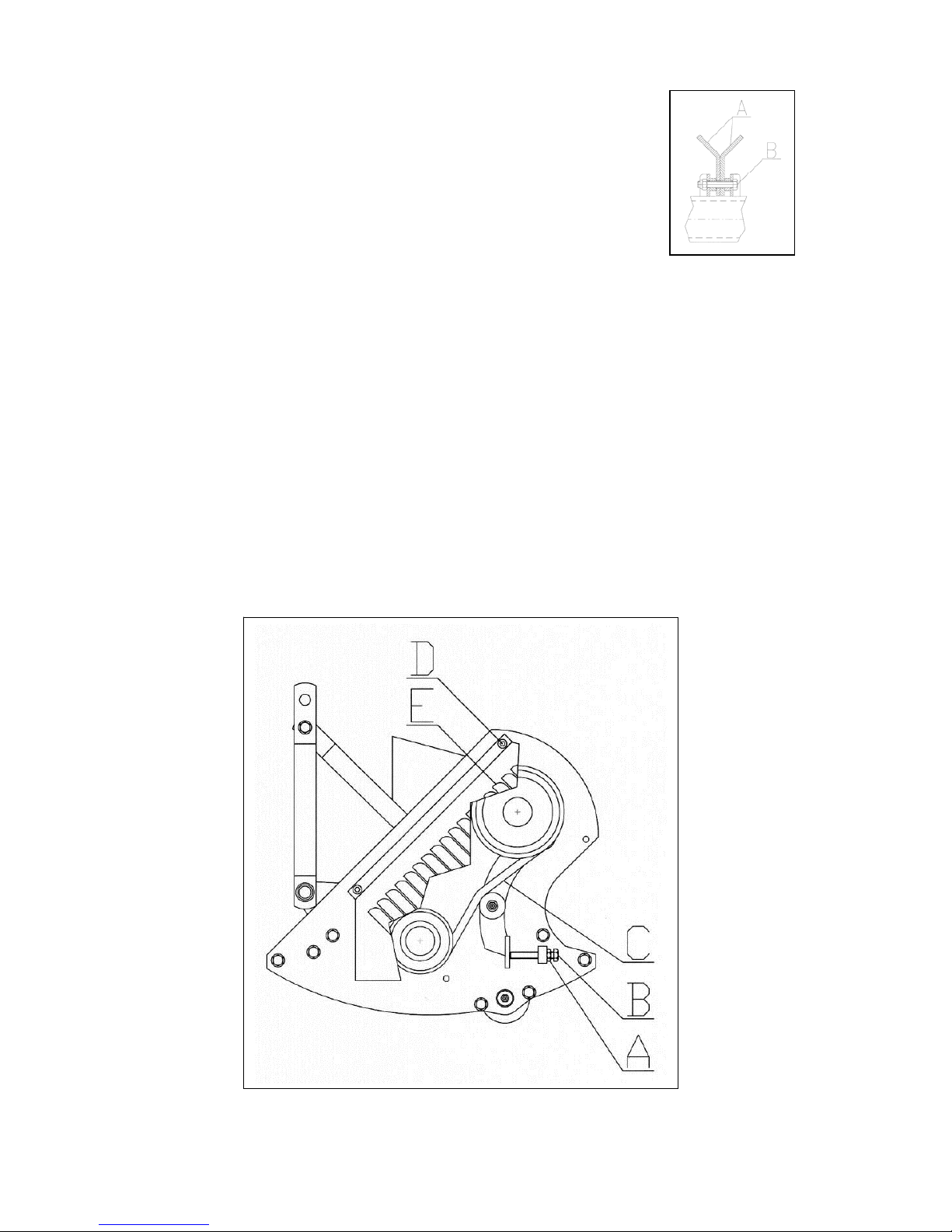
4. BELTS ADJUSTING AND REPLACEMENT
a) To adjust the tension of the transmission belts, operate as follow :
1. Disassemble safety protection “E” unscrewing the four screws “D”.
2. Unscrew the lock nut “A”, screw the screw “B” to increase or unscrew to decrease the tension.
3. After operation screw the lock nut “A” then assemble the safety protection “E”.
b) To change the transmission belts, operate as follow :
1. Disassemble safety protection “E” unscrewing the four screws “D”.
2. Unscrew the lock nut “A” then full unscrew the screw “B”
3. Remove the old belts “E”, to prevent adjusting problems you must replace both, and then assemble the
new referring to the characteristics in the SPARE PART LIST.
4. Make operations “2” and “3” point “a”.

11
PROBLEMS SOLVING
TROUBLES GROUNDS AND SOLUTIONS
Abnormal vibrations
-Not balanced rotor – Enquire a dealer.
-Loss of one or more tools – Replace.
-Damaged bearings – Replace.
Uneven or unsatisfactory cut -Damaged tools – Replace.
-Tools choice not good – Change with another type.

12
TRANSPORT
Except when working, moving the machine takes place when the machine is standing still and the
transmission is disconnected.
<Important>: keep speed low avoiding holes and ground roughness.
<Important>: Before begin the movements always make sure that the safety hooks be in position.
<Note when on the road, obey existing traffic laws. Exhibit the signal signs on the rear ends. Respect any
local laws there may be.
STORAGE
Store the machine in a dry place that isn't dusty.
INFORMATION ON DEMOLITION
At the end of its working life, the machine must be sent to be demolished and that can only be done
by an authorized authority, in accordance with the national laws in force for the environment. Therefore it is
necessary to get information from the qualified local authorities on the procedure to follow. The machine is
mainly composed of: iron materials and paints.
WARRANTY
The machine is covered by the manufacturer warranty for a period of 24 months.
The warranty is not applicable when:
a) The maintenance work has not been done correctly.
b) The machine has been used out of its own service.
c) The machine has been transformed or modified without the manufacturer's written authorization.

13
WORK AND MAINTENANCE SHEET
Every user should register on this sheet the facts about the life of the machine (both work and maintenance), so
as to attest its conditions.
DATE HOURS MAINTENANCE NOTE OPERATOR

14
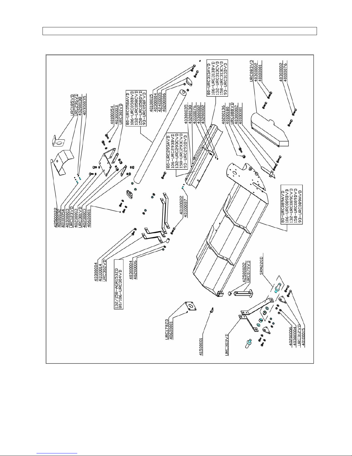
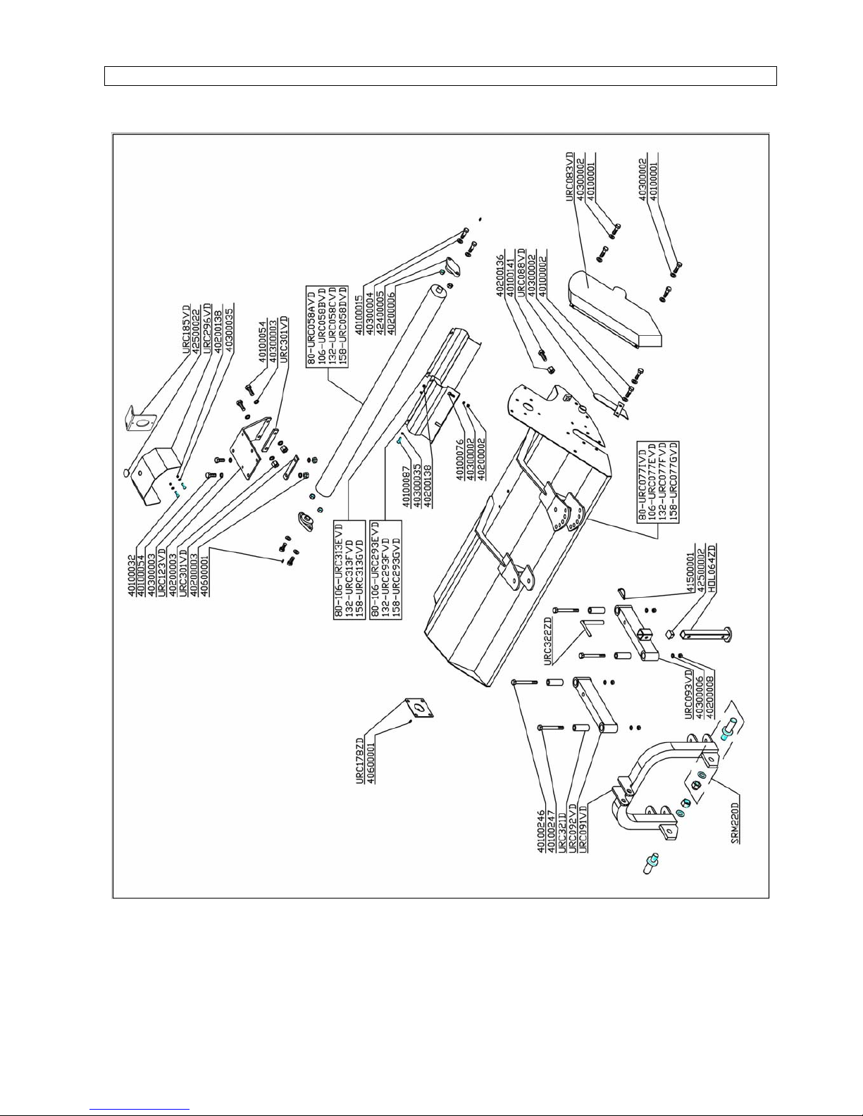
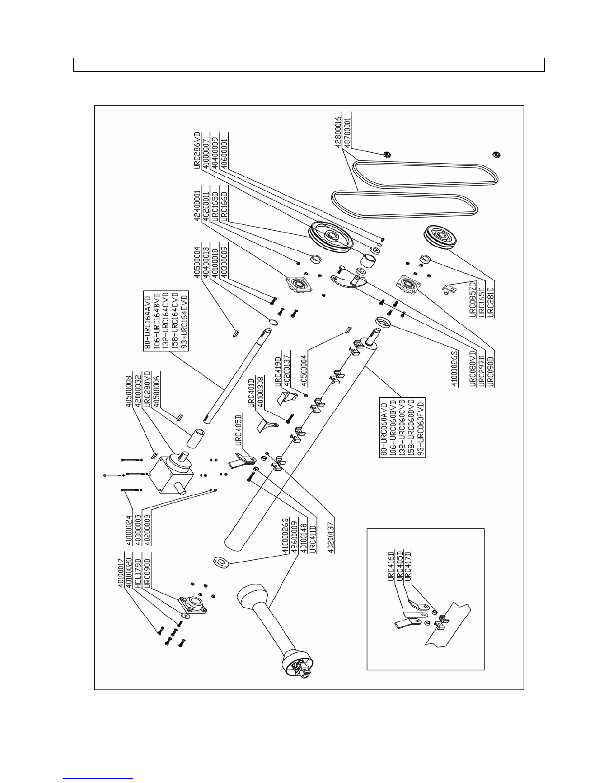
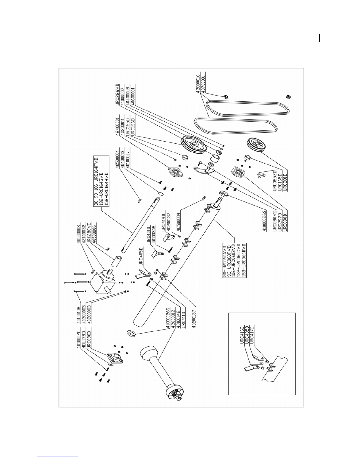
SPARE PARTS & OPTIONS
15
SHEETS
16
SHEETS T
17
MECHANISMS
18
MECHANISMS T

19
INDEX
PREFACE................................................................................................................................................................2
DESCRIPTION........................................................................................................................................................3
FUNCTION OF USE ............................................................................................................................................3
PERFORMANCES...............................................................................................................................................3
PERFORMANCES LIMIT.....................................................................................................................................3
STANDARD EQUIPMENTS.................................................................................................................................3
VARIANTS &OPTIONS.......................................................................................................................................3
TECHNICAL SPECIFICATIONS.............................................................................................................................4
SAFETY INFORMATIONS......................................................................................................................................5
PRESCRIZIONI GENERALI ................................................................................................................................5
SAFETY RESTRICTIONS ...................................................................................................................................5
RUNNING IN............................................................................................................................................................5
SAFETY SIGNS ON THE MACHINE......................................................................................................................6
INSTRUCTIONS FOR USE.....................................................................................................................................7
1. BEFORE BEGINNING WORK......................................................................................................................7
2. TO BEGINNING WORK................................................................................................................................7
3. AT THE END OF CUTTING OPERATION....................................................................................................7
MAINTENANCE INSTRUCTIONS..........................................................................................................................8
DIAGRAM “A” SCHEDULED MAINTENANCE ....................................................................................................8
1. GREASING...................................................................................................................................................9
2. OIL CHECK -OIL REPLACEMENT IN GEAR BOX......................................................................................9
3. TOOLS REPLACEMENT.............................................................................................................................10
4. BELTS ADJUSTING AND REPLACEMENT...............................................................................................10
PROBLEMS SOLVING.........................................................................................................................................11
TRANSPORT ........................................................................................................................................................12
STORAGE.............................................................................................................................................................12
INFORMATION ON DEMOLITION.......................................................................................................................12
WARRANTY..........................................................................................................................................................12
WORK AND MAINTENANCE SHEET..................................................................................................................13
SHEETS ................................................................................................................................................................15
SHEETS T .............................................................................................................................................................16
MECHANISMS......................................................................................................................................................17
MECHANISMS T...................................................................................................................................................18

20
Dichiarazione CE di conformità ai sensi della Direttiva Macchine 2006/42/CE
CE declaration of conformity under the Machinery Directive 2006/42/CE
Déclaration CE de conformité conforme a la Directive Machine 2006/42/CE
Eg konformitätserklärung im Sinne der Eg Vorschrift Maschine 2006/42/CE
“D E L M O R I N O S. R. L.”
- Via Caroni di Sotto n. 19 -
- 52033 CAPRESE MICHELANGELO (AREZZO) ITALIA-
Dichiara sotto la propria responsabilità che la macchina :“TRINCIA» è conforme ai requisiti di sicurezza e di tutela della
salute di cui alla “Direttiva Macchine 2006/42/CE.”
Per la verifica delle conformità alla direttiva sopramenzionata sono state consultate le norme armonizzate UNI EN ISO
12100:2010; 13857:2008; 4524-1:2010; 4254-12:2010.
Under Its own responsibility declare that the machine “FLAIL MOWER” complies to the safety and healt protection
requirement of machinery directive 2006/42/CE.
To verify the conformity to the above mentioned directive, have been consulted the harmonized standards UNI EN ISO
12100:2010; 13857:2008; 4524-1:2010; 4254-12:2010.
Déclarons sous notre responsabilité que la machine “BROYEUR” est conforme aux prescriptions en matière de sécurité et
de santé stipulée dans la directive machine 2006/42/CE.
Pour le contrôle des conformités des directive citées ont été consultées les règles unifiées UNI EN ISO 12100:2010;
13857:2008; 4524-1:2010; 4254-12:2010.
Erklärt hiermit in eigener Verantwortung dass der maschine “HÄCKSELMASCHINE” Die Schutzanforderungen und den
Gesundheitsschutz, gemäß der 2006/42/CE einhalt.
Für Überprüfung der Konformität der oben genannten Vorschriften wurden Vorschriften konsultiert UNI EN ISO 12100:2010;
13857:2008; 4524-1:2010; 4254-12:2010.
TRINCIA - FLAIL MOWER - BROYEUR - HACKSELMASCHINE
TYPE MODEL
Funny
C Funny
M Funny
S Funny
TC Funny
TM Funny
TS
80
93
106
119
132
158
Matr. n° : __________________Caprese Michelangelo li: ______________________
Custode del Fascicolo Tecnico : Dott. A. Del Morino, Via Caroni di Sotto 19, 52033 Caprese Michelangelo Arezzo Italy.
Keeper of the technical folder : Dott. A. Del Morino, Via Caroni di Sotto 19, 52033 Caprese Michelangelo Arezzo Italy.
Dépositaire du dossier technique: Dott. A. Del Morino, Via Caroni di Sotto 19, 52033 Caprese Michelangelo Arezzo Italy.
Verwalter der technischen Unterlagen:Dott. A. Del Morino, Via Caroni di Sotto 19, 52033 Caprese Michelangelo Arezzo
Italy.
This manual suits for next models
30
Table of contents
Other Del Morino Farm Equipment manuals


Popular Farm Equipment manuals by other brands

Schaffert
Schaffert Rebounder Mounting instructions

Stocks AG
Stocks AG Fan Jet Pro Plus 65 Original Operating Manual and parts list

Cumberland
Cumberland Integra Feed-Link Installation and operation manual

BROWN
BROWN BDHP-1250 Owner's/operator's manual

Molon
Molon BCS operating instructions

Vaderstad
Vaderstad Rapid Series instructions


