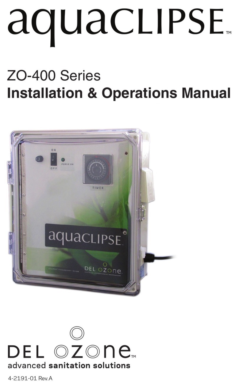
Del ozone TrioPure 25 User manual

TRIOPURE-25 CHLORINE GENERATOR CONTROLS BACTERIA AND
ALGAE IN DOMESTIC SWIMMING POOLS (SPA) WATERS
A MAXIMUM OF 57,000 L OF WATER CAN BE TREATED WITH ONE
TRIOPURE-25.
MAXIMUM OUTPUT OF HYPOCHLOROUS ACID EQUIVALENT TO 0.20 Kg
OF FREE AVAILABLE CHLORINE PER DAY
FOR SWIMMING POOLS, A MINIMUM OF 1 ppm OF FREE AVAILABLE
CHLORINE MUST BE MAINTAINED AND FOR SPAS A MINIMUM OF 3 ppm
OF FREE AVAILABLE CHLORINE MUST BE MAINTAINED
READ THE LABEL AND OPERATING MANUAL BEFORE USING
KEEP OUT OF REACH OF CHILDREN
REGISTRATION NUMBER 28566 PEST CONTROL PRODUCTSACT
DEL OZONE, 3428 BULLOCK LANE, SAN LUIS OBISPO, CA 93401
WARNING: OPERATING THE TRIOPURE-25 WITHOUT WATER FLOW
THROUGH THE CELL CAN CAUSE A BUILD UP OF FLAMMABLE GASES
WHICH CAN RESULT IN FIRE OR EXPLOSION.
LABEL FOR THE TRIOPURE-25
ENGLISH
TRIOPURE-25 REPLACEMENT CELL
REPLACEMENT CELL FOR THE CHLORINE GENERATING DEVICE TRIOPURE-25
REGISTRATION NUMBER 28566, PEST CONTROL PRODUCTS ACT. THIS CELL MUST BE USED
ON THIS MODEL OF CHLORINE GENERATING DEVICE
READ THE LABEL, THE INSTALLATION MANUALAND OPERATION MANUAL OF THE CHLORINE
GENERATING DEVICE TRIOPURE-25 BEFORE USING
DEL OZONE, 3428 BULLOCK LANE, SAN LUIS OBISPO, CA 93401
LABEL FOR THE TRIOPURE-25
REPLACEMENT CELLS
ENGLISH
1-800-676-1335
1-800-676-1335
09-JUL-2007
3580 Sueldo Street
3580 Sueldo Street
05-JAN-2009 2009-0003 Notification:
Change in Registrant Address
Notification Change

DEL Ozone · San Luis Obispo, CA 93401 · USA · 800-676-1335 · Fax: 805-541-8459 110105 / 4-0777 Rev E.
Installation and Operation Manual
TrioPure 25TM Soft Water
Sanitation System
AUTOMATIC
09-JUL-2007

IMPORTANT SAFETY INSTRUCTIONS
Read and Follow All Safety Instructions
•Read and be familiar with this manual before installing, operating, or performing maintenance on the TrioPureTM.
•The TrioPureTM must be installed and operated as specied.
•When installing and using this electrical equipment, basic safety precautions must always be followed.
•To reduce risk of electrical shock, turn off main pool pump and disconnect power to pool equipment prior to any installation or
removal of TrioPureTM components.
•All permanent electrical connections should be made using liquid tight ttings and conduit and be made by a certied electrician.
•A ground terminal marked: is located inside the compartment. To reduce the risk of electric shock, this terminal must be
connected to the grounding means provided in the electrical supply service panel with a continuous copper wire equivalent in
size to the circuit conductors supplying this equipment.
•A bonding lug is provided on the external surface of the TrioPureTM. To reduce the risk of electric shock, connect the local common
bonding grid in the area of the swimming pool, spa, or hot tub to these terminals with a copper conductor not smaller than 8 AG
for US and 6 AWG for Canadian installations.
•This product manufactures chlorine. Individuals with any type of chlorine sensitivity should take the appropriate precautions to
avoid injury or illness.
•A Ground Fault Circuit Interrupter (GFCI) must be installed between the TrioPure™ and the electrical supply.
•To avoid personal injury when working with pool chemicals, always wear rubber gloves and eye protection and work in a well-
ventilated area. Use caution when choosing a location to open and use chemicals as they may damage any surface in which
they come in contact.
•The TrioPureTM must not be installed directly above any heat source (e.g., heater). It must be at least 600 mm (2 ft.) above the
ground to allow free circulation of air around it. It must not be installed in a closed box.
•Level and mount the TrioPureTM on a wall or a post. If mounting the TrioPureTM on a post, it must be centered on a at panel of water-
proof material at least 457mmx610mm (18”x24”). Do not enclose the TrioPureTM in any box. Do not install it above any heat source.
Install the TrioPureTM a minimum of 3 m (10 ft.) from the pool edge. See your local building codes for any additional requirements.
•The TrioPure™ must be installed in an outdoor location, or indoors in a well-ventilated room, due to potential health concerns
related to inhalation of ozone. It must be installed so that it is level and with the orientation shown in Figures 1-9.
•Mount the TrioPure™ so that it is inaccessible to anyone in the pool. Never attempt any servicing while unit is wet.
•To avoid chlorinator cell damage, water pressure in the cell must not exceed 200 kPa (30 psi).
•For your safety, do not store or use gasoline, chemicals or other ammable liquids or vapors near this or any other appliance.
•Do not let anyone, especially small children, sit, step, lean, or climb on any equipment installed as part of your pool’s operational
system.
•WARNING: Always dilute acid in a bucket of pool water before adding to the pool. Never add water to acid. Always add chemicals
to water. Carefully follow acid manufacturer’s safety precautions. DO NOT MIX DIFFERENT CHEMICALS TOGETHER.
•WARNING: Short-term inhalation of high concentrations of ozone and long-term inhalation of low concentrations of ozone can
cause serious harmful physiological effects. DO NOT inhale ozone gas produced by this device.
•WARNING: Excessive chlorine levels can cause corrosion damage to swimming pool rails, ladders, heaters, heat exchangers,
light faceplates and other metallic equipment. Avoid over saturation of chlorine levels by checking chlorine often using a suitable
chlorine test device. Chlorine levels should not exceed 3 ppm. Always check chlorine levels before entering pool.
•WARNING: To reduce the risk of injury, do not permit children to use this product. This device must not be used with any bromine-
based pool or spa sanitizing products due to potential formation of by-products that may be of health concern.
SAVE THESE INSTRUCTIONS!
TrioPureTM Sanitation System
DEL Ozone · San Luis Obispo, CA 93401 · USA · 800-676-1335 · Fax: 805-541-8459
i
Maintain daily levels as determined by testing kit.

ADDENDUM FOR CANADIAN TRIOPURE INSTALLATIONS
The following information is for Canadian installations of the TrioPure and takes precedence over other information
in the manual.
1. WARNING: Heavy pool (or spa) usage and higher temperatures may require higher chlorine output to maintain
proper free available chlorine residuals.
2. When replacing the cell, only use replacement cells having a label that clearly states that it is a replacement cell
for the chlorine generating device TrioPure-25, REGISTRATION NUMBER 28566, PEST CONTROL PRODUCTS ACT.
3. DO NOT add pool/spa chemicals directly to the skimmer. This may damage the chlorinator cell.
4. Maintaining high salt and chlorine levels above recommended range can contribute to corrosion of pool and
spa equipment.
5. Check the expiry date of the test kit. Test results may be inaccurate if used after expiry date.
6. WARNING: To reduce the risk of injury, do not permit children to operate this device.
7. Follow all aspects of the local and National Electrical Code(s) when installing the TrioPure-25.
8. With high bather loads or high temperatures, the pool owner may add “liquid chlorine” with the active
ingredient of Sodium Hypochlorite to supplement the Chlorine production in the TrioPure-25.
9. When properly maintained and cleaned and under normal use conditions, the life expectancy of the chlorinator
cell and electrodes is three years minimum - approximately 15, 000 hours of operation.
10. NOTE: For outdoor pools, chlorine residual can be protected from destruction by sun’s rays by addition of
cyanuric acid stabilizer. See Section 5 of the manual for recommended cyanuric acid levels.
11. When the TrioPure is used to sanitize a pool and spa combination, the spa must be completely drained
periodically. The number of days between COMPLETE SPA DRAINAGE is equal to the volume of spa water in
liters, divided by 10 times the maximum number of daily spa users. Rell spa with water. Repeat DIRECTIONS
FOR USE of the device.
12. Pool Capacity:
• TrioPure-25: Up to 57,000 liters (15,000 gallons)
Swimming pool
Free available Chlorine 1.0 - 3.0 ppm
pH 7.2 - 7.8
Total alkalinity 100 - 120 ppm
Calcium hardness 200 - 300 ppm
Salt 3000-5000 ppm
Health and Hyperthermia warnings for spa devices:
• People with a medical condition should consult a physician before entering pool or spa water.
• Maximum spa water usage temperature is 40°C. Bathing in spa water at 40°C should not exceed 15 minutes.
TrioPureTM Sanitation System
ii
Maintain daily levels as determined by testing kit.

TrioPureTM Sanitation System
DEL Ozone · San Luis Obispo, CA 93401 · USA · 800-676-1335 · Fax: 805-541-8459 022105 / 4-0777
Table of Contents
SECTION 1
General Information
1A Description......................................................................... 1
1B Specications .................................................................... 1
SECTION 2
Installation
2A Verify Contents .................................................................. 2
2B Installation Tips................................................................. 2
2C Recommended Installation Materials ........................... 2
2D Mounting the TrioPureTM.................................................... 3
2E Plumbing ............................................................................ 3
2e-1 Installing the TrioPureTM Manifold ........................ 3
2e-2 PlumbingCongurationChart ............................. 3
2e-3 PlumbingCongurationFigures(1-9)................. 4
2F Electrical............................................................................. 9
SECTION 3
Pool Preparation
3A Important Information ..................................................... 10
3B What Kind of Salt to Use.................................................. 10
3C Where to Get Salt.............................................................. 10
3D How Much Salt to Use ...................................................... 10
3E How to Add Salt................................................................. 10
3F Pool Sizing Chart............................................................... 10
3G Salt Sizing Table ................................................................ 11
3H When to Add Salt .............................................................. 12
SECTION 4
Operation
4A Initial Start-Up Procedure ................................................ 13
SECTION 5
Monitoring & Maintenance
5A Front Panel Diagnostics ................................................... 16
5B Water Chemistry Parameters ......................................... 16
5b-1 Chlorine LevelRequirements.................................. 16
5b-2 pH Level..................................................................... 16
5b-3 Calcium Hardness and Total Alkalinity.........................17
5b-4 Cyanuric Acid (stabilizer/conditioner) .................. 17
5b-5 Salt Level (salinity)................................................... 17
5b-6 Saturation Index (Si)................................................ 17
5b-7 Nitrates and Phosphates ........................................ 17
5C Winterization ..................................................................... 17
5D TrioPureTM Maintenance .................................................... 18
5d-1 Injector....................................................................... 18
5d-2 Chlorinator Cell Plate Cleaning.............................. 18
5d-3 Chlorinator Cell Removal ........................................ 18
5d-4 Air Filters ................................................................... 19
SECTION 6
Troubleshooting
6A Troubleshooting the TrioPureTM ....................................... 20
SECTION 7
Contact, Ordering Information, Replace-
ment Parts and Warranty
7A Contacting Technical Support ......................................... 23
7B Ordering Information ....................................................... 23
7C Standard Replacement Parts List .................................. 23
7D Limited Warranty .............................................................. 24
The TrioPureTMisETLCertied.
iii

1
1B Specications
Power Requirements:
Rating: 120V, 3.0 A fuse, 60Hz, or
240V, 1.5 A fuse, 60Hz
Operating Temperature:
Air: 4º-49º C (40º-I20º F)
Water: 15º - 40º C (59º-104º)
Specications:
Dimensions: 38 x 48 x 18 cm (15” x 19.5” x 7.5”)
Weight: TrioPure-25: approx 17Kg (36lb)
Pool Capacity:
TrioPure-25: Up to 95,000 L (25,000 Gallons)
Chlorinator Production:
TrioPure-25: 7.9 g/h (174 g per day)
@ 3400 PPM salinity and 18º C (64.4º F)
water temperature at maximum setting
Water Flow Rate: 19 LPM
Salinity: 3,000-5,000 ppm (3,500 Nominal)
SECTION 1 General Information
1A Description
How Your TrioPureTM Sanitation System Works
Your TrioPureTM produces both ozone and chlorine. Ozone is
made by drawing air through Corona Discharge (CD) cells that
break down oxygen molecules, which then recombine into
ozone molecules. The TrioPure’s internal pump provides suf-
cient water ow through the TrioPureTM to draw this ozonated
air into the water stream. Chlorine is made by electrolyzing low
concentrations of salt water in the pool, freeing the chlorine
from the sodium chloride molecules in the salty water.
The TrioPureTM salt chlorination sub-system routinely shuts down
during cleaning mode and allows any scale that has developed
to slough off. This cleaning step dramatically lowers the amount
of scale that can attach to the salt chlorinator plates over
time and also greatly reduces the need for periodic cleaning.
The amount of chlorine produced by the TrioPureTM can be
adjusted by using the Chlorine Control knob in order to
compensate for higher chlorine demand during hot days or
increased bather load.
TrioPureTM Sanitation System
DEL Ozone · San Luis Obispo, CA 93401 · USA · 800-676-1335 · Fax: 805-541-8459
Illustration 1

2
2A Verify Contents
Inspect your TrioPureTM shipping box for the following items:
(1) TrioPure-25 with salt chlorinator cell attached
(1) Molded plastic bypass installation manifold
(1) 3.0 A fuse for 120 V & 1.5 A fuse for 240 V (in bag near TB1
Terminal Block)
(1) Manual
(1) Quick Reference Guide
2B Installation Tips
CAUTION: The bypass manifold must be correctly installed or
your TrioPureTM system will not work properly and the warranty will
be voided. The bypass manifold contains two check valves that
are matched to create the correct backpressure and anti-siphon
protection for optimum performance of your TrioPureTM.
•••The TrioPureTM sanitation system should be installed on resi-
dential pools only. The salt level in your TrioPureTM pool should
be between 3,000 and 5,000 ppm (3,500 recommended).
•••If you use solar panels for pool heating, your TrioPureTM must
be plumbed with the manifold before the solar heater, and
the water return from the TrioPureTM after solar heater. The
bubbles that can be created through your solar heater can
inadvertently shut off the TrioPure-25. See Figures 1, 2, 3,
7, 8 and 9.
••
•The TrioPureTM must be installed no more than 2.4 m (8 ft.)
above water level or no more than 1 m (3 ft.) (measured from
the top of the enclosure) below water level to maintain the
correct pressure and ow characteristics for optimum opera-
tion of the unit.
•••DO NOT USE copper or iron piping for the TrioPureTM installa-
tion as chlorine and ozone have corrosive effects. Consult
your pool professional for appropriate pool equipment piping
materials.
••Even though the TrioPureTM is designed for outdoor use, care
should be taken when choosing a mounting location. To
protect your investment, mount the TrioPureTM where it is
protected from the elements (i.e., direct sun, rain, dirt, sprin-
klers) and completely sheltered if possible while providing
adequate ventilation.
••
•If ozone bubbles are not desirable (for indoor pools, vinyl-lined
pools, pools with covers, negative edge pools, etc.), the addition
of a DEL Ozone Mixing-Degas Vessel (MDV-30) is recommended.
Contact your local pool equipment dealer or visit DEL Ozone’s
website at www.delozone.com to nd one near you.
SECTION 2 Installation
The most common pool and pool/spa congurations are
discussed in this manual. For questions on your specic
installation, please contact DEL Ozone at 800-676-1335,
extension 293.
TrioPureTM Sanitation System
DEL Ozone · San Luis Obispo, CA 93401 · USA · 800-676-1335 · Fax: 805-541-8459
•••“Salt & Pepper” ttings, eyeball ttings, or the use of a grav-
ity drains as return lines are recommended since they can
better mix and disperse treated pool water.
•••Plumb the TrioPureTM to the bypass manifold using a
minimum amount of plumbing fittings. This minimizes
backpressure.
•The TrioPureTM has been designed with an electronic water
ow switch. This device automatically shuts down both the
salt chlorinator and ozone subsystems when the water ow
through the TrioPureTM is interrupted. To prevent personal
injury and damage to the TrioPureTM salt chlorinator cell, do
not interfere with this system in any way. It is designed for
your protection and the protection of the TrioPureTM.
•••Always check the salt chlorinator cell frequently for the
accumulation of pool debris that may have bypassed the
pool lter. This can affect the operation of the ow switch,
ozone injector, pump, and salt chlorinator plates.
••
•Salt is not lost through evaporation, but is lost when water is
splashed out of the pool or during backwashing. Rainfall or
adding fresh water dilutes the salt concentration and you will
need to occasionally add more salt to the swimming pool. Check
salinity level before and after adding additional salt.
•••If the TrioPureTM is being installed on a new pool, do not add
salt for 2 weeks after the pool has been lled. This protects
plaster from staining and allows the nish to cure.
••Pool water with high calcium levels, or hard water,
cancauseexcessivecalcication[scale]intheChlo-
rinator Cell. Installation of a T-lter or Y-lter trap
with a 60-mesh screen near the Water Out line of the
TrioPure, along with frequent acid cleaning of the cell
plates[referenceSection5d-2:ChlorinatorCellPlate
Cleaning]willreducewaterhardnessovertime.The
monthly addition of a non-chlorine shock (Potassium
Monopersulfate or equivalent) to the pool will keep
thescalesoft,preventingtheltertrapfromclogging.
Removeandcleantheltertrapasnecessay.
2-C Recommended Installation Materials
•Liquid tight conduit, connectors & junction box, and appro-
priately sized and rated wire per local electrical codes.
Note: The TrioPure is designed for 1.5 cm (1/2”) NPT liquid
tight ttings
•Two 5 cm (2”) unions for manifold installation to pool return
line (use reducer bushings for 3 cm (1½”)).
•2 cm (3/4”) unions, ball-valves, and rigid PVC or Spa-Flex
tubing for installation from manifold to TrioPureTM.
•Mounting hardware for securing TrioPureTM to a stable sur-
face (wall, fence, post with backboard) sufcient to support
the unit.
Note: If you are mounting the TrioPureTM to the side of house
wall that is located near a bedroom, consider using a vibra-
tion dampening material to reduce vibration noise.

3
SECTION 2 Installation (Continued)
2D Mounting the TrioPureTM
IMPORTANT: A qualied swimming pool professional and certi-
ed electrician must install the TrioPureTM Sanitation System.
Refer to local building codes for any additional requirements.
If you need assistance in nding a qualied installer, please
contact our customer service department at 1-800-676-1335,
ext. 293, or visit www.delozone.com.
Step 1 - Before starting, pick a mounting location that:
•
Is 3 m (10 ft.) ft. minimum from the edge of pool
•Allows space for ease of plumbing and electrical installa-
tion. Review Sections 2E & 2F.
•The bottom of the TrioPureTM has a minimum clearance
of 0.6 m (2 ft.) from all obstacles for ease of visibility and
maintenance. Space must be allowed on all sides of the
enclosure for adequate ventilation and to allow the clear
cover to open completely.
•
Sufficient clearance on top and both sides for your
TrioPureTM for plumbing and electrical hardware access.
•The top of the TrioPureTM is no higher than 2.4 m (8 ft.) above
or lower than 1 m (3 ft.) below the water surface.
••• Avoid installing your TrioPureTM above any heat generating
source such as a heater or pump.
•Meets the guidelines in Section 2E (Plumbing) and Sec-
tion 2F (Electrical) in this manual
•
It is recommended that the TrioPure is mounted with
¼-20 galvanized hex bolts. The bolt mounting pattern
is 254 mm (10 in.) wide by 375 mm (14.75 ft.) high.
Screw in bottom bolts so that the head is 6.3 mm (¼
in.) from the mounting surface. Slide the TrioPure onto
these bolts and screw the upper bolts through the top
mounting holes on the enclosure.
Note: If installing your TrioPureTM below water level, an addi-
tional light-duty check valve is required after the chlorinator
cell to prevent backwash in the unlikely event of ozone check
valve failure while the unit has been powered down.
Step 2 - Level and mount the TrioPureTM on a wall or a post.
If mounting the TrioPureTM on a post, it must be centered on
a flat panel of waterproof material at least 457 mm x 610
mm (18” x 24”). Do not enclose the TrioPureTM in any box. Do
not install it above any heat source. Install the TrioPureTM a
minimum of 3m (10’ ft.) from the pool edge. Do not install
the TrioPure in direct sunlight. In locations where the daytime
temperatures regularly exceed 37ºC (100º F), the internal
thermal protection switch may shut down the TrioPure. When
the temperature drops the TrioPure power will be restored.
2E Plumbing
2e-1 Installing the TrioPureTM Manifold
Note: Turn off main pool pump and disconnect power before
installing the bypass manifold.
There are many different types of pool construction and pool
equipment congurations. The following pool conguration list
will help you determine which way to plumb your TrioPureTM for
optimal performance. Each conguration has an easy to plumb
illustration for installing the bypass manifold.
NOTE: The bypass manifold must be mounted horizontally to
prevent bubbles from returning to the TrioPureTM pump and
trippingtheowswitch.
TrioPureTM Sanitation System
DEL Ozone · San Luis Obispo, CA 93401 · USA · 800-676-1335 · Fax: 805-541-8459
Before installing the TrioPureTM bypass manifold, determine
whether your pool is a:
· New Pool (can I plumb a dedicated 2 cm (¾”) return)
· Existing Pool (returns already in place)
· Pool Only
· Pool/Spa combination
Also, determine whether your have anIn-Floor Cleaning System
(ICS) or Solar Heater installed in your existing pool (or plan to
install one on your new pool).
The plumbing diagrams shown on the following pages are
schematic representations of the various pool congurations
and plumbing lengths are for reference only.
2e-2 Plumbing Conguration Chart
If your pool is:
New Pool
Pool Only
No ICS
No Solar / Solar - See Figure 1
If your pool is:
Existing Pool
Pool Only
No ICS
No Solar / Solar - See Figure 2
If your pool is:
Existing Pool
Pool Only
ICS
No Solar / Solar - See Figure 3
If your pool is:
New Pool
Pool Spa Combo
No ICS
No Solar - See Figure 4
If your pool is:
Existing Pool
Pool Spa Combo
No ICS
No Solar - See Figure 5
If your pool is:
Existing Pool
Pool Spa Combo
ICS
No Solar - See Figure 6
If your pool is:
New Pool
Pool Spa Combo
No ICS
Solar - See Figure 7
If your pool is:
Existing Pool
Pool Spa Combo
No ICS
Solar - See Figure 8
If your pool is:
Existing Pool
Pool Spa Combo
ICS
Solar - See Figure 9

4
TrioPureTM Sanitation System
2e-3 Plumbing Congurations Figures 1-9
Figure 1 - (New Pool, Pool Only, No ICS, No Solar, Solar):
· Manifold to be plumbed between the lter and heater. In the case of Solar, the manifold is to be installed before the
diverter valve that serves both the solar and non-solar heaters.
· TrioPureTM return port of the bypass manifold capped off.
· Return from TrioPure plumbed to a dedicated 2 cm (¾”) return to the lowest point of the pool.
·
To minimize the size of ozone bubbles, use a dispersion cap or main drain cover. This may require a stub-up to the
appropriate size for the tting.
·
Del recommends installing 2 cm (
¾
”) ball valves on the inlet and outlet of the Triopure to facilitate Salt Cell removal for
cleaning and a ball valve after the Bypass Manifold to control water ow through the Salt Cell.
Figure 2 - (Existing Pool, Pool Only, No ICS, Solar, No Solar):
· Bypass Manifold plumbed between the lter and heater.
Note-In the case of Solar, the manifold is to be before the diverter valve that serves both the solar and non-solar heaters.
· TrioPureTM return port of the bypass manifold capped off.
· Return from TrioPureTM plumbed into tee after the heater(s).
Note-In the case of Solar the TrioPure return is to be after the tee where the solar heater joins the main return.
·
Del recommends installing 2 cm (
¾
”) ball valves on the inlet and outlet of the Triopure to facilitate Salt Cell removal for
cleaning and a ball valve after the Bypass Manifold to control water ow through the Salt Cell.
A
SOLAR
HEATER
POOL
Optional
A
POOL
SOLAR
HEATER
Optional
TrioPureTM
TrioPureTM
DEL Ozone · San Luis Obispo, CA 93401 · USA · 800-676-1335 · Fax: 805-541-8459

2e-3 Plumbing Congurations (Continued)
Figure 3 - (Existing Pool, Pool Only, ICS, Solar, No solar):
· Manifold to be plumbed between the lter and heater.
· TrioPureTM return port of the bypass manifold capped off.
· Return from TrioPureTM plumbed to the line of the ICS that goes to the lowest point of the pool.
- This is after the ICS diverter valve.
- A light duty check valve must be placed between the diverter valve and point where the TrioPureTM enters the ICS line.
·
Del recommends installing 2 cm (
¾
”) ball valves on the inlet and outlet of the Triopure to facilitate Salt Cell removal for
cleaning and a ball valve after the Bypass Manifold to control water ow through the Salt Cell.
Figure 4 - (New Pool, Pool Spa Combination, No ICS, No solar):
· Manifold to be plumbed in the pool return after the 3-way valve that diverts water between the pool and spa.
· TrioPureTM return port of the bypass manifold capped off.
· Return from TrioPureTM plumbed to a dedicated 2 cm (¾”) return to the lowest point of the pool.
· To minimize the size of ozone bubbles, use a dispersion cap or main drain cover. This may require a stub-up to the appro-
priate size for the tting.
·
Del recommends installing 2 cm (
¾
”) ball valves on the inlet and outlet of the Triopure to facilitate Salt Cell removal for
cleaning and a ball valve after the Bypass Manifold to control water ow through the Salt Cell.
TrioPureTM Sanitation System
5
DEL Ozone · San Luis Obispo, CA 93401 · USA · 800-676-1335 · Fax: 805-541-8459
A
ICS
POOL
SOLAR
HEATER
Optional
J
J
POOL
SPA
TrioPureTM
TrioPureTM

TrioPureTM Sanitation System
6
2e-3 Plumbing Congurations (Continued)
Figure 5 - (Existing Pool, Pool Spa Combination, No ICS, No solar):
· Manifold to be plumbed in the pool return after the 3 way valve that diverts water between the pool and spa.
· Return from TrioPureTM plumbed back into the bypass manifold.
·
Del recommends installing 2 cm (
¾
”) ball valves on the inlet and outlet of the Triopure to facilitate Salt Cell removal for
cleaning and a ball valve after the Bypass Manifold to control water ow through the Salt Cell.
Figure 6 - (Existing Pool, Pool Spa Combination, ICS, No solar):
· Manifold to be plumbed in the pool return after the 3 way valve that diverts water between the pool and spa.
· Return from TrioPureTM plumbed to the line of the ICS that goes to the lowest point of the pool.
- This is after the ICS diverter valve.
- A light duty check valve must be placed between the diverter valve and the point where the TrioPureTM enters the
ICS line.
·
Del recommends installing 2 cm (
¾
”) ball valves on the inlet and outlet of the Triopure to facilitate Salt Cell removal for
cleaning and a ball valve after the Bypass Manifold to control water ow through the Salt Cell.
J
J
POOL
SPA
J
J
POOL SPA
ICS
TrioPureTM
TrioPureTM
DEL Ozone · San Luis Obispo, CA 93401 · USA · 800-676-1335 · Fax: 805-541-8459

7
TrioPureTM Sanitation System
DEL Ozone · San Luis Obispo, CA 93401 · USA · 800-676-1335 · Fax: 805-541-8459
2e-3 Plumbing Congurations (Continued)
Figure 7 - (New Pool, Pool Spa Combination, No ICS, Solar):
· Manifold to be plumbed between the lter and heater.
· TrioPureTM return port of the bypass manifold capped off.
· Return from TrioPureTM plumbed to a dedicated 2 cm (¾”) return to the lowest point of the pool.
· An automated shut-off valve needs to be put in the line between the bypass manifold and the TrioPureTM, which is tied into
the Pool/Spa control system, and shuts off water to the TrioPure when in spa mode.
- If this is overlooked, the TrioPure will pump water from the spa into the pool, when in spa mode.
- To minimize the size of ozone bubbles, use a dispersion cap or main drain cover. This may require a stub-up to the
appropriate size for the tting.
·
Del recommends installing 2 cm (
¾
”) ball valves on the inlet and outlet of the Triopure to facilitate Salt Cell removal for
cleaning and a ball valve after the Bypass Manifold to control water ow through the Salt Cell.
Figure 8 - (Existing Pool, Pool Spa Combination, No ICS, Solar):
· Manifold to be plumbed between the lter and heater.
· TrioPureTM return port of the bypass manifold capped off.
· Return from TrioPureTM plumbed into a tee in the main pool return after the 3 way valve that diverts water between the pool
and spa.
· An automated shut-off valve needs to be put in the line between the bypass manifold and the TrioPureTM, which is tied into
the Pool/Spa control system, and shuts off water to the TrioPureTM when in spa mode.
- If this is overlooked, the TrioPure will pump water from the spa into the pool, when in spa mode.
·
Del recommends installing 2 cm (
¾
”) ball valves on the inlet and outlet of the Triopure to facilitate Salt Cell removal for
cleaning and a ball valve after the Bypass Manifold to control water ow through the Salt Cell.
J
A
SPA
POOL
J
SOLAR
HEATER
J
J
AJ
POOL
J
SPA
SOLAR
HEATER
TrioPureTM
TrioPureTM

8
TrioPureTM Sanitation System
2e-3 Plumbing Congurations (Continued)
Figure 9 - (Existing Pool, Pool Spa Combination, ICS, Solar):
· Manifold to be plumbed between the lter and heater.
· TrioPureTM return port of the bypass manifold capped off.
· Return from TrioPureTM plumbed to the line of the ICS that goes to the lowest point of the pool.
- This is after the ICS diverter valve.
- A light duty check valve must be placed between the diverter valve and the point where TrioPureTM enters the ICS line.
· An automated shut-off valve needs to be put in the line between the bypass manifold and the TrioPureTM, which is tied into
the Pool/Spa control system, and shuts off water to the TrioPure when in spa mode.
- If this is overlooked, the TrioPureTM will pump water from the spa into the pool, when in spa mode.
·
Del recommends installing 2 cm (
¾
”) ball valves on the inlet and outlet of the Triopure to facilitate Salt Cell removal for
cleaning and a ball valve after the Bypass Manifold to control water ow through the Salt Cell.
Special Note about Spillway Valves on Pool/Spa Combinations without Solar. If a spillway valve is used, the line which takes water
from the pool into the spa creating the overow effect, it must be equipped with a light duty check valve to prevent water from being
diverted back into the pool, when in spa mode, and any lines to or from the TrioPure must be plumbed after it.
J
A
J
ICS
POOL
J
SPA
SOLAR
HEATER
TrioPureTM
DEL Ozone · San Luis Obispo, CA 93401 · USA · 800-676-1335 · Fax: 805-541-8459

9
TrioPureTM Sanitation System
DEL Ozone · San Luis Obispo, CA 93401 · USA · 800-676-1335 · Fax: 805-541-8459
2F Electrical
IMPORTANT: Electrical connections must be made by a
certied electrician. Use copper conductors only. Follow
local and NEC codes. Connect only to a circuit protected by
a Class A GFCI.
Step 1 - Determine the voltage required for your installation.
Your TrioPureTM is congurable for either 120 V or 240 V AC.
Step 2 - For 120 V installations, install the 3.0 A fuse (3A G
type) into the fuse holder. For 240 V installations, install the
1.5 A fuse (3 AG type) into the fuse holder. The fuses are in a
bag attached inside the enclosure near the terminal block.
Warning: Failure to install the correct fuse voids the warranty
and can present a potential re and/or electrical hazard.
Step 3 - Open the front clear cover by opening the latch on
the right side of the enclosure.
Step 4 - Remove the front panel by pulling off the Chlorine
Control Knob and unscrewing four (4) Phillips head 6-32
screws. Locate the terminal block (TB-1).
Figure-10TerminalBlock120 VCongurations
Figure - 11 Terminal Block 240 V Congurations
Step5 - The main power wiring should be routed through 1.5
cm (½”) hole on the left side of the enclosure using appropriate
liquid tight strain relief or conduit (not supplied).
Step 6 - Connect the main wires to TB-1 as show in Figure 10
for 120 V installations or Figure 11 for 240 V installations.
Step 7 - Connect the local common bonding grid in the area of
the swimming pool, spa or hot tub to the bonding lug (on the
left exterior of the unit) with an insulated or bare solid copper
conductor not smaller than 8 AWG (US) or 6 AWG (Canada).
Step 8 - Attach the cover plate with the four (4) Phillips head
6-32 screws. Replace the Chlorine Control Knob onto the
extended “D” control shaft. Ensure that the ON/OFF switch
is in the “OFF” position. Close and latch the clear cover.
Note: The TrioPureTM must be hard-wired to the AC line side for
24 hour operation to 120 V/60 Hz or 240 V/60 Hz ONLY using
liquid tight ttings/conduit and wire gauges meeting local codes
for the voltage required. Use a permanent marker to indicate
either 120 V or 240 V conguration on the side label found on
the left side of the TrioPureTM.

SECTION 3 Pool Preparation
3A Important Information
If the TrioPureTM is being installed on a new pool, do not add
salt for 2 weeks after pool has been lled to help protect
plaster from staining.
Pool water must be at the proper salinity level, temperature,
and chemically balanced before operating the TrioPureTM.
3B What Kind of Salt to Use
Use 99.6% pure or better sodium chloride water softening or
feed salt work best with your TrioPureTM. The ner the grain,
the easier it will be to dissolve the salt quickly and completely
(pellets are much harder to dissolve than ne grain salt).
Common brand names of salt to use are Cargil and Morton.
Note: Salt with anti-caking agents (yellow prussiate of soda,
or “YPS”) may cause staining of pool linings and xtures and
should not be used.
3C Where to Get Salt
Salt can be purchased at a pool supply, building supply, feed
supply, or major home and garden department store.
3D How Much Salt to Use
Always use a salinity test strip (such as Aquacheck White for
salt or LaMotte Tracer Meter- found through local pool supply
dealer) or digital salinity meter to determine salt level in pool
water prior to adding any salt. Capture water from about 457mm
(18” in.) deep in a container, and then test this water sample. Add
enough salt to obtain a salinity of approximately 3,500 ppm - Refer
to ‘Salt Sizing Table’ (Figure 14) on pages 11-12.
3E How to Add Salt
Step 1 - Evenly disperse the proper amount of salt around the
perimeter of the pool. Run the main pool circulation pump for
24 hours and agitate any undissolved salt deposited at the
bottom of the pool with a pool brush. Allow 24 hours or longer
for salt to fully dissolve.
IMPORTANT: To avoid damage to your TrioPureTM chlorinator,
never operate the TrioPureTM if the salinity level is under 3,000
ppm.
It is easy to add more salt to your pool but difcult to remove
excess salt through draining.
CAUTION: Do not add salt to the skimmer box.
3F Pool Sizing Chart
If you don’t know the size of your swimming pool, you must rst
determine the volume before adding large quantities of salt.
For rectangular pools, simply calculate:
length (m) x width (m) x average depth (m) =
cubic meters (m3)
For oval pools, simply calculate:
length (m) x width (m) x average depth (m) x 1.1 =
cubic meters (m3)
For round pools, simply calculate:
(diameter(m))2x average depth (m) x 1.3 =
cubic meters (m3)
width
length
average
depth
length average
depth
width
Rectangular Pool
Oval Pool
Figure 12
Figure 13
10
TrioPureTM Sanitation System
DEL Ozone · San Luis Obispo, CA 93401 · USA · 800-676-1335 · Fax: 805-541-8459

11
Continued - Pounds of Salt (99.6% pure Sodium Chloride) Needed for 3,500 PPM Salt Level
DEL Ozone · San Luis Obispo, CA 93401 · USA · 800-676-1335 · Fax: 805-541-8459
TrioPureTM Sanitation System
Volume in Cubic Meters from 19 to 95 (5,000 to 25,000 gal)
continued on next page
3G Salt Sizing Table
Figure 14
18,750 28,125 37,500 46,875 56,250 65,625 75,000 84,375 93,750
(5,000) (7,500) (10,000) (12,500) (15,000) (17,500) (20,000) (22,500) (25,000)
0 66 100 133 166 199 232 266 299 332
250 62 92 123 154 185 216 247 277 308
500 57 85 114 142 171 199 228 256 285
750 52 78 104 130 156 183 209 235 261
1000 47 71 95 119 142 166 190 213 237
1250 43 64 85 107 128 149 171 192 213
1500 38 57 76 95 114 133 152 171 190
1750 33 50 66 83 100 116 133 149 166
2000 28 43 57 71 85 100 114 128 142
2250 24 36 47 59 71 83 95 107 119
2500 19 28 38 47 57 66 76 85 95
2750 14 21 28 36 43 50 57 64 71
3000 9 14 19 24 28 33 38 43 47
3250 5 7 9 12 14 17 19 21 24
3500 0 0 0 0 0 0 0 0 0
95,625 97,500 99,375 101,250 103,125 105,000 106,875 108,750 110,625
(25,500) (26,000) (26,500) (27,000) (27,500) (28,000) (28,500) (29,000) (29,500)
0 339 345 352 358 365 372 378 385 392
250 314 321 327 333 339 345 351 358 364
500 290 296 302 307 313 319 324 330 336
750 266 271 276 282 287 292 297 303 308
1000 242 247 251 256 261 266 270 275 280
1250 218 222 226 230 235 239 243 248 252
1500 193 197 201 205 209 212 216 220 224
1750 169 173 176 179 183 186 189 193 196
2000 145 148 151 154 156 159 162 165 168
2250 121 123 126 128 130 133 135 138 140
2500 97 99 101 102 104 106 108 110 112
2750 73 74 75 77 78 80 81 83 84
3000 48 49 50 51 52 53 54 55 56
3250 24 25 25 26 26 27 27 28 28
3500 0 0 0 0 0 0 0 0 0
112,500 121,875 131,250 140,625 150,000 159,375 168,750 178,125 187,500
(30,000) (32,500) (35,000) (37,500) (40,000) (42,500) (45,000) (47,500) (50,000)
0 398 432 465 498 531 564 597 631 664
250 370 401 432 462 493 524 555 586 616
500 341 370 398 427 455 484 512 541 569
750 313 339 365 391 417 443 469 496 522
1000 285 308 332 356 379 403 427 450 474
1250 256 277 299 320 341 363 384 405 427
1500 228 247 266 285 303 322 341 360 379
1750 199 216 232 249 266 282 299 315 332
2000 171 185 199 213 228 242 256 270 285
2250 142 154 166 178 190 202 213 225 237
2500 114 123 133 142 152 161 171 180 190
2750 85 92 100 107 114 121 128 135 142
3000 57 62 66 71 76 81 85 90 95
3250 28 31 33 36 38 40 43 45 47
3500 0 0 0 0 0 0 0 0 0
Current Salt
Residual Level
in PPM (mg/l)
Kilograms of Salt (99.6% pure Sodium Chloride) Needed for 3500 PPM Salt Residual
Pool Volume in Litres (Gallons)
Current Salt
Residual Level
in PPM (mg/l)
Kilograms of Salt (99.6% pure Sodium Chloride) Needed for 3500 PPM Salt Residual
Current Salt
Residual Level
in PPM (mg/l)
Pool Volume in Litres (Gallons)
Volume in Cubic Meters from 96.5 to 112 (25,000 to 29,500 gal)
See Figure 14 below for complete salt sizing information on pools up to 187,500 L (50,000) gallons.

3H When to Add Salt
Step 1 – Determine the size of your pool in cubic meters. Please
see Section 3F.
Step 2 – Check the salinity of the pool water. Always use a
salinity test strip or electronic salinity meter to determine the
salt level in the pool water prior to adding any salt.
Step 3 – Use the Salt Sizing Table (Section 3G) to determine
how much salt you’ll need. You will also need to add about 0.6
kg (1.25 lbs) of stabilizer (Cyanuric Acid) for every 23 kg (50
lbs) of salt added to the pool. For example, if adding 340 kg
(750 lbs), the quantity of stabilizer needed would equal 340
kg (750 lbs) / 23 kg X 1.25 = 8.5 kg.
Note: To add Cyanuric Acid, slowly sprinkle into the skimmer.
Step 4 – Turn on the main pool pump with suction coming from
the main pool drain.
Step 5 – Add salt directly to the pool [DO NOT add to the skim-
mer box] by dispersing it around the outside edge of the pool.
Step 6 – Use a pool brush to mix and help dissolve the salt. Keep
the main pump running for 24 hours.
Step 7 – Check the pool salinity. If the salt level is much lower or
higher than expected, rst re-check your calculations for adding
salt. Second, check the pool for any undissolved salt and con-
tinue to brush and run the main pump as needed.
REMINDER: Even if the salt concentration is higher than 3,000
ppm, the ‘Low Salt’ light may ash if the water temperature is
at the low end of the specied range or the Chlorine Control
knob is at a low setting (1-4 shown on the LED display). This
is especially true during the initial preparation and start-up. In
this situation, the TrioPure may not display ‘10’ at the maximum
setting. The addition of more salt to the pool may allow the
Chlorine Output display to reach maximum readings.
12
TrioPureTM Sanitation System
3G Salt Sizing Table (Continued)
DEL Ozone · San Luis Obispo, CA 93401 · USA · 800-676-1335 · Fax: 805-541-8459
Figure 14, Cont.
18,750 28,125 37,500 46,875 56,250 65,625 75,000 84,375 93,750
(5,000) (7,500) (10,000) (12,500) (15,000) (17,500) (20,000) (22,500) (25,000)
0 66 100 133 166 199 232 266 299 332
250 62 92 123 154 185 216 247 277 308
500 57 85 114 142 171 199 228 256 285
750 52 78 104 130 156 183 209 235 261
1000 47 71 95 119 142 166 190 213 237
1250 43 64 85 107 128 149 171 192 213
1500 38 57 76 95 114 133 152 171 190
1750 33 50 66 83 100 116 133 149 166
2000 28 43 57 71 85 100 114 128 142
2250 24 36 47 59 71 83 95 107 119
2500 19 28 38 47 57 66 76 85 95
2750 14 21 28 36 43 50 57 64 71
3000 9 14 19 24 28 33 38 43 47
3250 5 7 9 12 14 17 19 21 24
3500 0 0 0 0 0 0 0 0 0
95,625 97,500 99,375 101,250 103,125 105,000 106,875 108,750 110,625
(25,500) (26,000) (26,500) (27,000) (27,500) (28,000) (28,500) (29,000) (29,500)
0 339 345 352 358 365 372 378 385 392
250 314 321 327 333 339 345 351 358 364
500 290 296 302 307 313 319 324 330 336
750 266 271 276 282 287 292 297 303 308
1000 242 247 251 256 261 266 270 275 280
1250 218 222 226 230 235 239 243 248 252
1500 193 197 201 205 209 212 216 220 224
1750 169 173 176 179 183 186 189 193 196
2000 145 148 151 154 156 159 162 165 168
2250 121 123 126 128 130 133 135 138 140
2500 97 99 101 102 104 106 108 110 112
2750 73 74 75 77 78 80 81 83 84
3000 48 49 50 51 52 53 54 55 56
3250 24 25 25 26 26 27 27 28 28
3500 0 0 0 0 0 0 0 0 0
112,500 121,875 131,250 140,625 150,000 159,375 168,750 178,125 187,500
(30,000) (32,500) (35,000) (37,500) (40,000) (42,500) (45,000) (47,500) (50,000)
0 398 432 465 498 531 564 597 631 664
250 370 401 432 462 493 524 555 586 616
500 341 370 398 427 455 484 512 541 569
750 313 339 365 391 417 443 469 496 522
1000 285 308 332 356 379 403 427 450 474
1250 256 277 299 320 341 363 384 405 427
1500 228 247 266 285 303 322 341 360 379
1750 199 216 232 249 266 282 299 315 332
2000 171 185 199 213 228 242 256 270 285
2250 142 154 166 178 190 202 213 225 237
2500 114 123 133 142 152 161 171 180 190
2750 85 92 100 107 114 121 128 135 142
3000 57 62 66 71 76 81 85 90 95
3250 28 31 33 36 38 40 43 45 47
3500 0 0 0 0 0 0 0 0 0
Current Salt
Residual Level
in PPM (mg/l)
Kilograms of Salt (99.6% pure Sodium Chloride) Needed for 3500 PPM Salt Residual
Pool Volume in Litres (Gallons)
Current Salt
Residual Level
in PPM (mg/l)
Kilograms of Salt (99.6% pure Sodium Chloride) Needed for 3500 PPM Salt Residual
Current Salt
Residual Level
in PPM (mg/l)
Pool Volume in Litres (Gallons)
Volume in Cubic Meters from 113 to 189 (30,000 to 50,000 gal)

13
TrioPureTM Sanitation System
DEL Ozone · San Luis Obispo, CA 93401 · USA · 800-676-1335 · Fax: 805-541-8459
SECTION 4 Operation
4A Initial Start-Up Procedure
CAUTION: Depending on water temperature and turnover in
pool, it may take several days for the salt to dissolve and salin-
ity levels to be measured accurately. Do not add additional
salt to pool unless all salt is dissolved and salinity measure-
ments are consistently less than 3,000 ppm.
CAUTION: Operating the TrioPure with pool salinity below
3,000 ppm will severely reduce cell life.
Step 1 - Before starting the TrioPure, manually add chlorine
to the water for the rst week to a minimum level of 1 ppm
and ensure that all water chemistry parameters are within
the specied limits. Check the water chemistry, water tem-
perature, and salt level (salinity) and adjust as needed – all
must be within the limits specied in Section 5B, Monitoring &
Maintenance, of this manual before starting the TrioPureTM.
Step 2 - Turn on main pool pump before starting the TrioPureTM.
Note: Ozone may cause temporary clouding of water in pool on
initial startup (rst 24-48 hours) as the ozone causes organic
matter to occulate (stick together) and minerals to precipitate
out so that they can be trapped in the pool lter. Clean lter as
needed until pool water is clear.
Step 3 - Become familiar with the controls, indicators, and
features of the TrioPureTM. See Figure 15 below (TrioPure-50
shown)
1. Chlorine Production Display
2. Chlorine Control Knob
3. Low Salt Indicator
4. High Salt Indicator
5. Ozone Production Indicators
1
2
5
10 9
8
3
4
7
6
6. Water Flow Indicator
7. Water Temp. Indicator
8. On/Off Switch
9. Fuse (right side)
10. Serial Number # (left side)
Figure 15

14
TrioPureTM Sanitation System
Step 4 - Unfasten the latch on right side of the TrioPureTM and
open clear cover.
Step 5 - Turn the Chlorine Control knob to ‘Min’
(Counter-clockwise).
Step 6 - Switch the TrioPureTM power switch to ‘ON’.
Step 7 - Observe the color of the following status LED lights:
Ozone Production cell
TrioPure-25 = O3Cell 1, O3Cell 2
Water Flow
Water Temperature
All above LEDs should be green. If any LEDs are red, please
see the Troubleshooting section, Chapter 6A for assistance.
Step 7a - Observe that the Chlorine Production LED display
reads ‘OF’.
Figure 16
Figure 17
Figure 18
DEL Ozone · San Luis Obispo, CA 93401 · USA · 800-676-1335 · Fax: 805-541-8459

15
TrioPureTM Sanitation System
DEL Ozone · San Luis Obispo, CA 93401 · USA · 800-676-1335 · Fax: 805-541-8459
Step 8 - Look for bubbles of ozone in the water at the injector
(found in the chlorinator cell).
Step 9 - Turn Chlorine Control knob up about half way (point-
ing straight up).
Step 10 - Observe Chlorine Production display: the Low Salt
light will ash and the display will read “0” until the TrioPureTM
chlorinator comes on line.
Step 11 - Check pool free chlorine levels every 24 hours, and
adjust Chlorine Control knob as necessary to get between
1.0 and 3.0 ppm.
Figure 19
Figure 20
Figure 21
Table of contents
Other Del ozone Water Filtration System manuals
Popular Water Filtration System manuals by other brands

Atlantic Ultraviolet
Atlantic Ultraviolet Mighty Pure MP16A owner's manual

SunSun
SunSun CBG-500 Operation manual

Hayward
Hayward XStream Filtration Series owner's manual

Contech
Contech DownSpout StormFilter Operation and maintenance

Teka
Teka Airfilter MINI operating instructions

Wisy
Wisy LineAir 100 Installation and operating instructions

Schaffner
Schaffner Ecosine FN3446 Series User and installation manual

Pentair
Pentair FLECK 4600 SXT Installer manual

H2O International
H2O International H20-500 product manual

Renkforce
Renkforce 2306241 operating instructions

Neo-Pure
Neo-Pure TL3-A502 manual

STA-RITE
STA-RITE VERTICAL GRID DE FILTERS S7D75 owner's manual