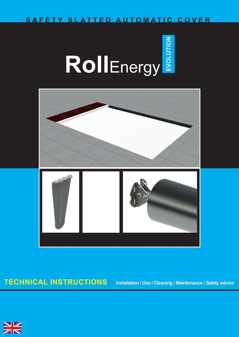
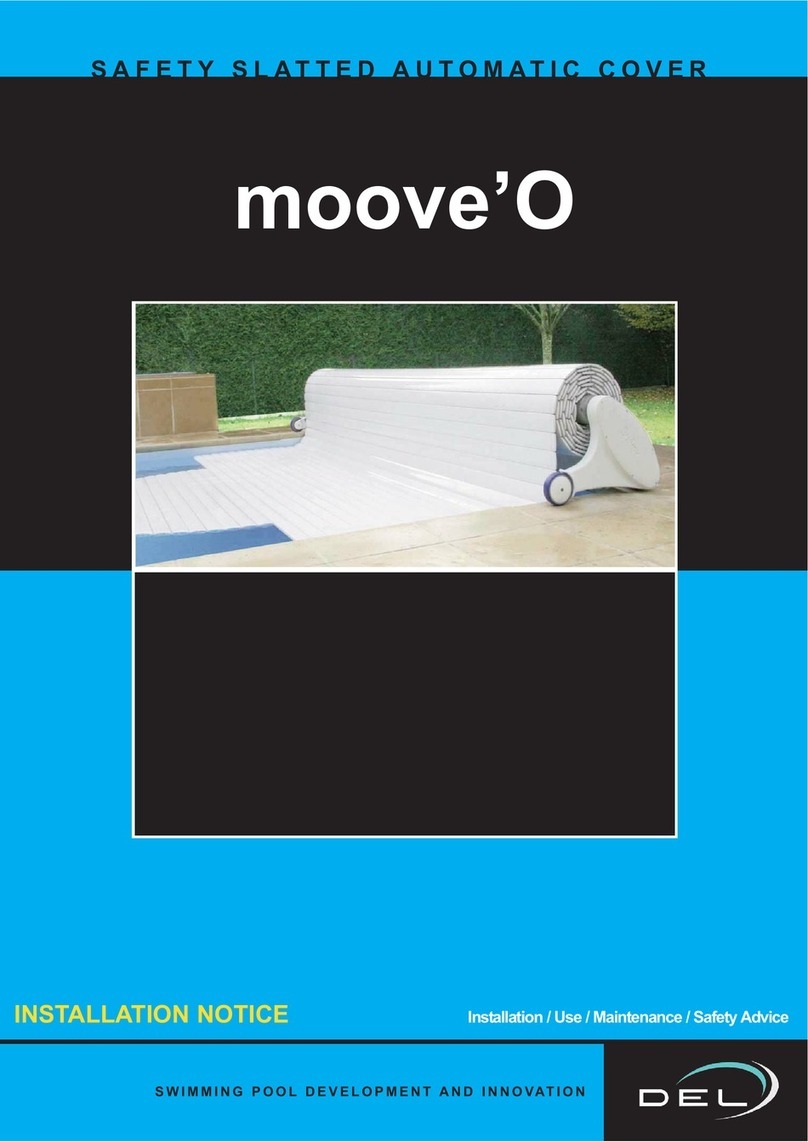
DEL RollEasy2 Owner's manual

RollEasy2
AUTOMATIC ABOVE-GROUND COVER
TECHNICAL INSTRUCTIONS Installation / Use / Cleaning / Maintenance / Safety advice

2
information
NOTICE TO BE GIVEN TO THE USER AFTER INSTALLATION IS COMPLETE
PLEASE READ CAREFULLY AND KEEP IN A SAFE PLACE.
Electric and solar versions
The motor is located in the stand and can be accessed from inside the housing.
The power supply comes from an electric box located in the technical room, or from 2 batteries
placed in the terminal on the motor side for the solar version.
The automatic stops are adjusted directly on the motor.
Manual version
Rolling and unrolling operations are carried out using the removable wheel.
The cover is composed of watertight PVC articulated
slats that float on the surface of the water.
Currently covers with overflows and covers with removable steps on the side are not
compliant with standard NF P 90-308.
Unless otherwise specified by the manufacturer, immersion alarms are not compatible
with roll-Easy 2 covers.

1
2 3
3
information
-The motor (compliant with electric standards) is located in the tube and can
be accessed from the exterior of the terminal.
- Adjustment of the “mechanical automatic stop” locking the cover in place once
it has been fully unrolled or rolled, is done
directly on the motor.
- Solar version: The solar panel and batteries are built into the tube fitted.
- Electric version: The electrical control box is fitted in a technical room close to
the pool. (see page 13 for the box size)
Slats:
- The cover itself is made from unleaded PVC slats (this material conforms to
anti-ageing requirements as defined in the NF T 54 405-1 Standard), they are
watertight and hinged and will float on the surface of the water.
- The gap between the side and the cover must be <= 70 mm.
- The cover is connected to the tube using white straps that are attached to the
first slat of the cover.
- There are fixture straps at the start and end of the cover used to fix the cover
to the fastening kit fixed to the side of the pool.
Fastening kits:
1-Push-lock 2-Quick-Lock 3-Passe-sangle
3 fixture modes: (surface mount – insert mount – hanging mount)
- The fastening kits are positioned on each width of the pool.
(the number varies depending on the pool configuration)
- These fastening systems are triggered by a tool or a double action.
Optional:
- “Chlorinator coupling” (electric version only):
Connected to the roller and chlorinator control box, this option is used
to automatically reduce chlorine production when the pool is closed in order
to avoid excess chlorine in the water.
Cover control:
- Wi-Key “wireless”
Or
- Key switch

x1 x1 x1
x1
x6
x6 x4 x4 x2
x1
x8 x6 x12 x8
x1x1
x6
x6 x4 x6x8 x1
x2
x1 x1
x4
4
DELIVERED PARTS
Slats (variable number of packs) Locking kits (1 pack)
Free
terminal
Electric
terminal
or or
Solar
terminal
Manual
terminal
3 fastener models:
surface mounted – insert mounted – hanging mounted
69 mm Slats
Electric box
Motor
Motorised roller
stand
Manual roller
stand
or
or or
Electric or solar version assembly pack
Lag screw
M8x80
Ø12
Plug
THEF screw
M8x30
TBHC screw
M6x30
TF screw
M3x16
adjustment
ring
M6 Ø12x1.2
washer
M8 Ø24x2
washer
M6 Nut M8 nut
Wrench
pen
Male Allen key
size 4
2
wrenches and
a keyring in
the document
bag
Manual version assembly pack
Lag screw
M8x80
Ø12
Plug
THEF screw
M8x30
M8 Ø24x2
washer
M8 nut
Male Allen key
size 4
electric version
battery
solar version
battery
charger
solar version
wheel
manual version
M6 wavy
washer
Description

T22
Ø8 - 12
5
PACKING LIST
e.g. - for a 4 x 8 m pool
1 0.80 x 0.60 x 0.55 pallet —- 40kg
1 4.30 x 0.20 m pack —– 25 kg
4 5 x 0.25 x 0.20 m packs —– 150 kg
Total weight: 205 Kg
ASSEMBLY INSTRUCTIONS
3 hours
TOOLS REQUIRED FOR ASSEMBLY (INSTALLATION – 2 PERSONS)
information

AB
A = B
6
x2 x4
x8
x4
1
2
60 cm max
Quicklock :
15 cm mini
15 cm mini
Quick-lock
6
60 cm max
Quicklock :
15 cm mini
ASSEMBLING AND FIXING THE ROLLER
Installation
Centre of the pool
Remove the terminal door.
Free side
Free side Free side
Free side
Motor side
Motor side
Motor side
Wheel side
Stand Stand
x2
THEF screw
M8x30
x4
M8 nut
x10
M6 nut
x4
TBHC screw
M6x30
only for the electric and solar versions on the
motor side
Assembling and placing the roller on the pool
assembling the terminals
Solar and electric version Manual version
Sharp corner
Rounded corners or
Filtration unit or other

Ø12
x3
x3
x2
x1
x8
x3
x4 x4
7
Installation
Free side
Lag screw
M8x80
Ø12
Plug
TF screw
M3x16
adjustment
ring
M6 Ø12x1.2
washer
M6 Ø12x1.2
washer
M8 Ø24x2
washer
M6 nut
Solar and electric version
Fixture of the roller to the ground
Installing the motor (electric and solar version)
Make small rotating
movement with the motor to
facilitate the insertion
align the key with the notch

21
3
4
8
ELECTRIC VERSION WIRING
Installation
230 V Power supply
(Sheathed RO2V)
2 x 4 mm² - up to 16 m in length.
2 x 6 mm² - from 16 to 25 m in length.
The electric box must be fitted in a dry place.
The installation must be compliant with standard C15-
100.
(Last applicable version) ask your electrician for advice
or ask your electricity provider)
All our boxes have a single phase 230 Volt (50Hz)
power supply.
The power required at the input terminals is 0.15 Kw.
A suitably sized circuit breaker must be fitted before the
junction box and equipped with a 30 mA ground fault
system.

21
3
4
9
ELECTRIC VERSION WIRING
Installation

10
21
3
4
-+ F
CO
Installation
WIRING - SOLAR VERSION - WI-KEY
230 V Power supply
(Sheathed RO2V)
2 x 4 mm² - up to 16 m in length.
2 x 6 mm² - from 16 to 25 m in length.
The electric box must be fitted in a dry place.
The installation must be compliant with standard C15-
100.
(Last applicable version) ask your electrician for advice
or ask your electricity provider)
All our boxes have a single phase 230 Volt (50Hz)
power supply.
The power required at the input terminals is 0.15 Kw.
A suitably sized circuit breaker must be fitted before the
junction box and equipped with a 30 mA ground fault
system.

11
++
--
21
3
4
-+ F
CO
Installation
WIRING - ELECTRIC VERSION - WI-KEY

12
INSTALAÇÃOInstallation
WI-KEY INSTALLING THE CONTROL BOX
- It must be located in a place from which it is possible to check
that no one enters the pool during the manoeuvre.
- It is mandatory to install the locking «strip».
- Before fixing the control box, check that the emitter is
communicating with the receiver.
”if the motor does not run => check the power supply polarity
The support must be attached to a fixed support
Closing
Opening Stops the current action
Keyboard lock
red / green flashing = emitter locked
Emitter unlocking procedure see «page 27»
The emitter must be located outside volume 0.
The distance between the emitter and the receiver must not exceed:
- 50 m in an obstacle-free zone.
- 25 m behind a basic wall.
- 15 m behind several walls or an especially thick wall.

13
1
2
45°
INSTALAÇÃOInstallation
Slat assembly
COVER INSTALLATION
skid
Cover start (“début de volet”) pack
Steps (“escalier”) pack
End of cover (“fin de volet”) pack
“CLICK”
along the whole
length of the slat
Repeat the movement until all the slats are completely clipped together
Make sure the slats are in the right direction
Roller
water
By clipping
By sliding
remove the cap
35 cm
If necessary, cut
the sides to ease
the passage of the
cover and avoid
rubbing
strap

14
Installation
notch
skid assembly
The skids are used to orient the cover at the start of closure.
The holes are drilled at the factory.
Assembly of the strap between the cover and the tube
The surface to
be glued must
be clean and
dry

I
0
II
I
0
II
1
2
3
4
15
Installation
Command logic verification
Adjustment
AUTOMATIC STOP ADJUSTMENT
The arrows indicate the cover’s
direction of movement
Turning in the +direction increases the extension of the cover
Turning in the -direction decreases the extension of the cover
If the command logic is incorrect,
reverse cables 1 and 2 on
the motor output.
(see wiring diagram)
Opening the
cover
Closing the
cover

x* х х х
хх х х х х х х
х
16
Installation
The positions of the locking kits on the
pool are shown on the plans delivered
with the slats.
OF THE LOCKING KITS
Positioning rules
Any changes to the positions of the locking kits must follow the rules explained below.
Please contact us for any other cases.
Without
step unit With Roman
step unit
kit at the end
of a roman
step unit
2 kits at max
50 cm from
the edge
kit at max 50 cm
from the edge
1 kit centred if < 1 m
1 kit at 50 cm from the edge if < 2 m
2 kits if > 2 m
* X must never exceed 2 m
With side
step unit
With straight
or
diagonal
step unit

Ø8 17
5 cm
mini
For concrete and panel pools
PUSH-LOCK INSTALLATION
For concrete and panel pools
50 mm
water level
Acceptable limit of
level variation
50 mm
Hang mounted version
Insert mounted model
Installation
A water level regulator is mandatory
50 mm
50 mm
recommended
5 cm
mini
50 mm
50 mm
For concrete and concrete block pools, as well as pools with
wall thickness greater than or equal to 8 mm
Surface mounted model
60 mm “minimum” Once the resistance
point has been
reached stop screwing,
this would deteriorate
the fixture quality.
Concrete
After reaching the
resistance point, make
3 more turns of the
screwdriver
to finish tightening.
Concrete block
Plug
Washer Washer
5 cm
Ø8
VBA TF Torx
stainless steel A4 Ø6
x 50 wood screw
Screw cap
Hollow white
Ø16 washer
Inserted
part
Screw cap
Hang mount support
Ø12 Nylon
plug
Stainless steel nut
A4 M10
Cale
13 mm
VBA TF Torx
stainless steel A4
Ø6 x 50 wood screw
Hollow white
Ø16 washer
INOX
M6 washer
water level
Acceptable limit of
level variation
recommended
water level
Acceptable limit of
level variation
recommended
Universal 8 x 40 plug
VBA TF Torx stainless
steel A4 Ø6 x 50 wood
screw
Hollow white Ø16
washer
Screw cap

Ø8
18
INSTALLATION QUICK-LOCK
A water level regulator is mandatory
5 cm
mini
VBA TF Torx
stainless steel A4 Ø6
x 50 wood screw
Hollow white
Ø16 washer
Inserted
part
adjustement
For concrete and panel pools
5 cm
5 cm
For concrete and panel pools
5 cm
5 cm
5 cm
mini
5 cm
5 cm
For concrete and concrete block pools, as well as pools with
wall thickness greater than or equal to 8 mm
5 cm
Ø8
60 mm “minimum”
Plug
Washer
Once the resistance
point has been
reached stop screwing,
this would deteriorate
the fixture quality.
Concrete
After reaching the
resistance point, make
3 more turns of the
screwdriver
to finish tightening.
Washer
Concrete block
water level
Acceptable limit of
level variation
recommended
water level
Acceptable limit of
level variation
recommended
water level
Acceptable limit of
level variation
recommended
Hang mounted version
Insert mounted model
Surface mounted model
Hang mount support
Ø12 Nylon
plug
Stainless steel nut
A4 M10
adjustment
VBA TF Torx stainless steel
A4 Ø6 x 50 wood screw
Hollow white Ø16
washer
Cale
13 mm
Inox M6 washer
Universal 8 x 40 plugs
adjustment
VBA TF Torx stainless
steel A4 Ø6 x 50 wood
screw
Hollow white Ø16
washer
Installation

Ø8 19
INSTALLATION PASSE-SANGLE
A water level regulator is mandatory
5 cm
mini
5 cm
mini
For concrete and panel pools
For concrete and panel pools
For concrete and concrete block pools, as well as pools with
wall thickness greater than or equal to 8 mm
5 cm
5 cm
5 cm
60 mm “minimum”
Plug
Washer
Once the resistance
point has been
reached stop screwing,
this would deteriorate
the fixture quality.
Concrete
After reaching the
resistance point, make
3 more turns of the
screwdriver
to finish tightening.
Washer
Concrete block
5 cm
5 cm
5 cm
Ø8
water level
Acceptable limit of
level variation
recommended
water level
Acceptable limit of
level variation
recommended
water level
Acceptable limit of
level variation
recommended
Hang mounted version
Insert mounted model
Surface mounted model
Universal 8 x 40 plugs
Universal 8 x 40 plugs
VBA TF Torx stainless
steel A4 Ø6 x 50 wood
screw
Hollow white Ø16
washer
VBA TF Torx stainless steel
A4 Ø6 x 50 wood screw
VBA TF Torx stainless steel
A4 Ø6 x 50 wood screw
Hollow white
Ø16 washer
Hollow white Ø16 washer
Inserted
part
Installation

++ +
1
20
INSTALLATION OF THE STRAP-HOLDER ANCHOR EYEBOLT
INSTALLATION OF THE STRAPLOCK STRAP
Centre of the straplock
between
25 et 40 cm
Eyebolt for concrete beach
Eyebolt for wooden beach
depth : 5 cm
depth : 4,5 cm
The head of the
eyebolt must be
higher than the
beach surface
Do not force the eyebolt into a drill
hole of a smaller diameter than this
Cruciform
Ø4 x 25
Protective
sheath
single strap
strap
sheath
staple
loop
Stretch the strap
the cover must touch the
underside of the straplock
Place the strap in position after
the loop and crimp
the 2 strap thicknesses pass inside the stable
double strap
stapleloop
or
Place the sheath around the staple
and heat using a liester
thermostat 5 to 6
Be careful not to burn the strap
Ø20
Ø20
côté mât
Installation
Table of contents
Other DEL Lighting Equipment manuals
Popular Lighting Equipment manuals by other brands
LIVARNO LUX
LIVARNO LUX 970-K manual
Lightmybricks
Lightmybricks LEGO HARRY POTTER THE SHRIEKING SHACK & WHOMPING... installation guide
IMG STAGE LINE
IMG STAGE LINE LED-10SPOT instruction manual

North Light
North Light OCL-573-BR-UK Installation
HAMPTON BAY
HAMPTON BAY HB-4133-OR Use and care guide
HAMPTON BAY
HAMPTON BAY L08207 Use and care guide
