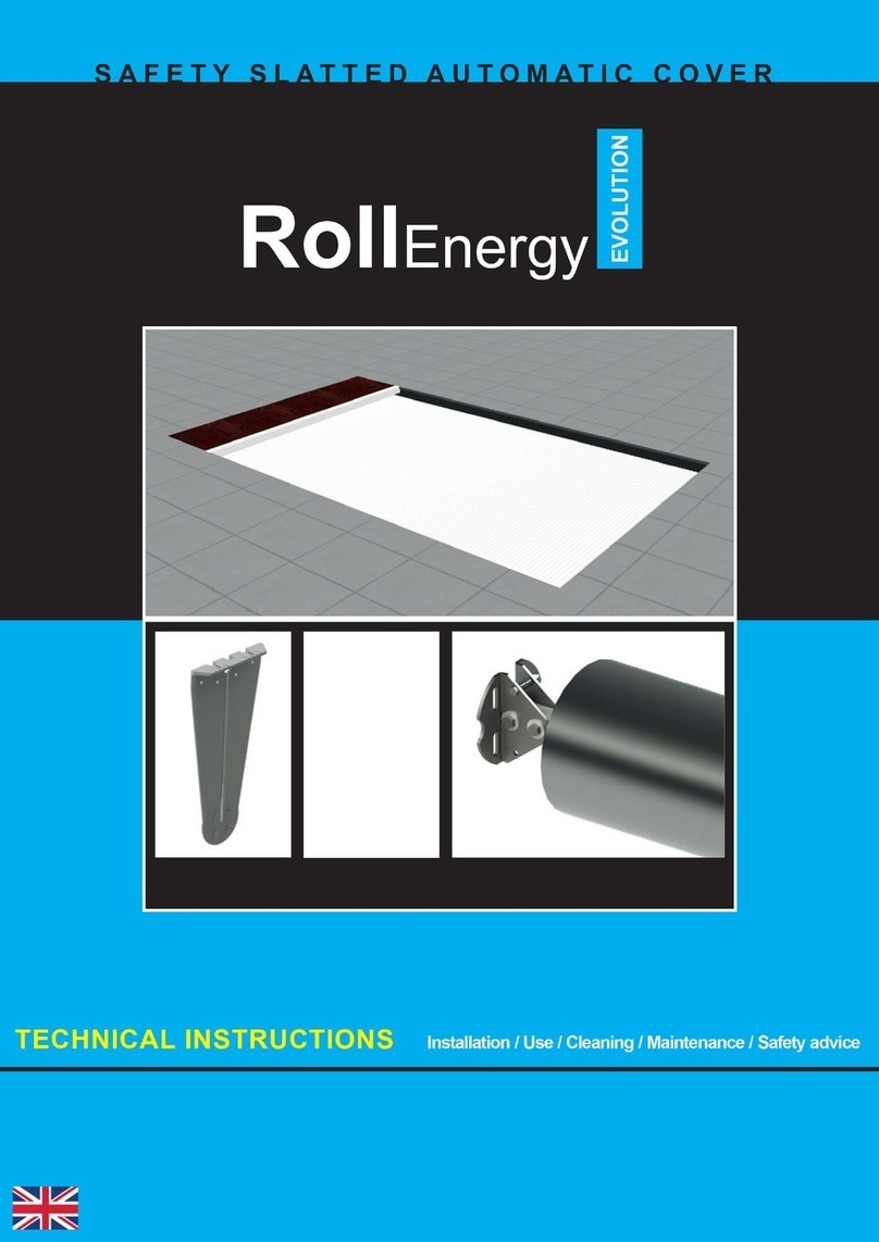
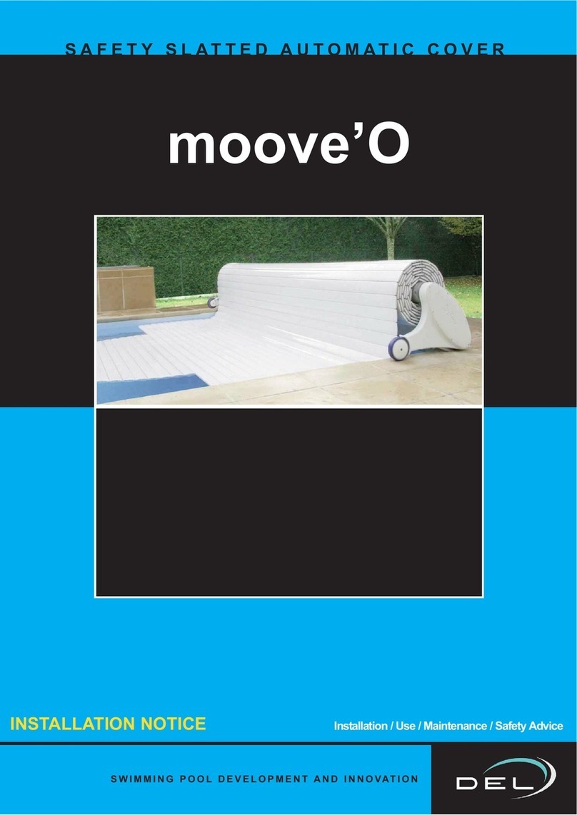
DEL CONTURA Owner's manual

CONTURA
AUTOMATIC SAFETY COVER FOR ABOVE GROUND POOLS
TECHNICAL INSTRUCTIONS Installation / Use / Cleaning / Maintenance / Safety advice

2
Information
NOTICE TO BE GIVEN TO THE USER AFTER INSTALLATION IS COMPLETE
PLEASE READ CAREFULLY AND KEEP IN A SAFE PLACE.
Automatic above ground pool motorised roller using either mains electricity or solar power.
The opening or closure operation requires about 2 minutes for one person and about 3 minutes
to lock or unlock the attachment kits.

3
a
b
c
Information
-The motor (compliant with electric standards) is located in the tube and
can be accessed from the terminal fitted.
- Mechanical or electronic “automatic stop depending on the model” used
to block the cover when it is completely unrolled or rolled on the tube.
- Solar version: The solar panel(s) and the
batteries are built into the terminal fitted.
- Electric version: The electrical control box is fitted in a technical room close
to the pool. (box size see page 13, 15)
Slats :
-The cover itself is made from unleaded PVC slats (this material conforms to
anti-ageing requirements as defined in the NF T 54 405-1 Standard), they
are watertight and hinged and will float on the surface of the water.
- The gap between the side and the cover must be <= 70 mm.
- The cover is connected to the tube using white straps that are attached to
the first slat of the cover.
- There are fixture straps at the start and end of the cover
used to fix the cover to the fastening kit fixed to the side of the pool.
Fastening kits:
3 models: (a - Push-lock / b - Quick-lock / c - Straplock)
3 fixture modes: (anchored façade – embedded in façade – hang mounted)
- The fastening kits are positioned on each width of the pool.
(the number varies depending on the pool configuration)
- These fastening systems are triggered by a tool or a double action.
Optional:
- “Chlorinator coupling” (electric version only):
Connected to the roller and chlorinator control box, this option is used
to automatically reduce chlorine production when the pool is closed in order
to avoid excess chlorine in the water.
The roller:
66 cm 66 cm
55 cm 55 cm
30 cm 30 cm
42 cm at the shaft 42 cm at the shaft
Control:
- “Wireless” Wi-key
Or
- Key switch
- “Automatic switch”:
Protects the system if locking kits are unreleased (attachment kits or other)
when opening the pool. If the cover jams, the motor stops automatically.

x1 x1 x2
x1
x6 x8
x6 x8
x6
x6 x6
4
x1
+
+
of
x2 x2 x2
6.5 Ah 12 V
Aqua 9 PL3210
8.5 Ah 12 V
20.3 Ah 12 V
x1
x2
x1 x1
X14 x4 x8x2 x1
x4
x1
3x16
nr. 4
M8x30
M6x16
M8 12x60
M8x80
M8
M8
M6
M6x16
M8 12x60
M8x80
nr. 4:
M8x50
M8x50
M8
x4
M6
DELIVERED PARTS
Descriptif
OPTION - CHLORINE INHIBITOR
or or
or
or
or
or
or
removable
motorisation
Fixed
motorisation
removable
motorisation
Fixed
motorisation
or or or or
Option Wi-Key

Ø8 - 12 - 20
nr.10
nr.13
nr.17
3 u
5
T25
PACKING LIST
e.g. - for a 4 x 8 m pool
1 0.80 x 0.60 x 1 m pallet —- 55kg
1 4.30 x 0.20 m pack —– 25 kg
4 5 x 0.25 x 0.20 m packs —– 150 kg
Total weight : 230 Kg
TOOLS
ASSEMBLY INSTRUCTIONS
Descriptif

6
D + 11 cm
D
Aqua 9 PL3210
x8
M8x30
ASSEMBLY / POSITIONING / FIXTURE
Installation
Remember to have a
sheath fitted to connect
the electric control box and
the motor terminal. see positioning
rules
(page 8)
D = (measurement between the
terminal - pool width) / 2
MAINS version
SOLAR version
Place the solar panel on the
sunniest side
Instructions before installation
or
Install the adjustment screw

7
x2
x8x4
M8x30
M8
x4
M8
Installation
Assembling the roller
Contura removable motorisation
motor side
motor side
Contura fixed motorisation

8
Installation
With
straplock
or
Push-lock
With
Quick-lock
Position 1
Depending on the pool corners and the fastener kits on the roller side
Sharp corner Rounded corners or cut-off corners
Min = 15 cm Min = 15 cm
Max = 60 cm
Max = 60 cm
Position of the roller on the pool

9
=
=
5 mm 5 mm
5 mm
Installation
Position 2
motor side
centre of the width
Contura removable motorisation
Contura fixed motorisation
motor side

10
nr.17
Ø12
x2
3x16
x6
x6 x6
M8
M8 12x60
M8x80
Installation
Fix
5 mm
Fix the adjustment bar
Before fixing, check that there is an operating gap of 5 mm on each side.
(see “positioning 2” previous page)
Levelling
ground

11
10
M6
M6
x4 x4
x8
Installation
INSTALLING THE MOTOR
Contura removable motorisation
Make small rotating
movements with the motor
to ease its fitting.

12
2
1
34
-+C OF
3
2
1+
-
+
-
Installation
WIRING - CONTURA SOLAR - VERSION WITH REMOVABLE MOTORISATION / WI-KEY

2
1
34
-C OF
13
+
25
20
10
2 x 4 mm² - up to 16 m in length.
2 x 6 mm² - from 16 to 25 m in length.
WIRING - CONTURA MAINS - WITH REMOVABLE MOTORISATION / WI-KEY
The electric control box must be fitted in a dry room.
The installation must comply with the NF C15-100 standard and
CEI 60364
(Last applicable version) ask your electrician for advice or contact
your electricity provider)
All our control boxes use a 230 Volt single phase (50Hz) power
supply.
The required power at the input terminals is 0.15 Kw.
Upstream from the control box a suitably sized circuit breaker
with a 30 mA ground fault device must be provided.
Installation
230 V Power supply
(U1000RO2V in a sheath) compliant with applicable standards
+ 2 x 1 mm² - STOP SEL OPTION
Wiring - refer to the manual supplied with the
product

14
2
1
34
3
2
1
+
-
+
-
Installation
WIRING - CONTURA SOLAR - VERSION WITH REMOVABLE MOTORISATION / KEY SWITCH

15
2
1
34
25
20
10
WIRING - CONTURA MAINS - WITH REMOVABLE MOTORISATION / KEY SWITCH
Installation
The electric control box must be fitted in a dry room.
The installation must comply with the NF C15-100 standard and
CEI 60364
(Last applicable version) ask your electrician for advice or contact
your electricity provider)
All our control boxes use a 230 Volt single phase (50Hz) power
supply.
The required power at the input terminals is 0.15 Kw.
Upstream from the control box a suitably sized circuit breaker
with a 30 mA ground fault device must be provided.

16
21
7
6
7
6
21
67
2
1
Installation
230 V Power
supply
automatic
switch
WIRING - CONTURA MAINS - WITH FIXED MOTORISATION / WI-KEY
The electric control box must be fitted in a dry room.
The installation must comply with the NF C15-100 standard and
CEI 60364
(Last applicable version) ask your electrician for advice or contact
your electricity provider.
All our control boxes use a 230 Volt single phase (50Hz)
power supply.
The required power at the input terminals is 0.15 Kw.
Upstream from the control box a suitably sized cir-
cuit breaker with a 30 mA ground fault device must be
provided.
(RO2V in a sheath)
Chlorinator
2 x 4 mm² - up to 16 m
2 x 6 mm² - from 16 to 25 m
3 x 1,5 mm²
LED meanings (see page 35)

21
7
6
67
7
6
21
2
1
17
230 V Power
supply
automatic
switch
WIRING - CONTURA MAINS - WITH FIXED MOTORISATION / KEY SWITCH
The electric control box must be fitted in a dry room.
The installation must comply with the NF C15-100 standard and
CEI 60364
(Last applicable version) ask your electrician for advice or contact
your electricity provider.
All our control boxes use a 230 Volt single phase (50Hz)
power supply.
The required power at the input terminals is 0.15 Kw.
Upstream from the control box a suitably sized cir-
cuit breaker with a 30 mA ground fault device must be
provided.
(RO2V in a sheath)
Chlorinator
2 x 4 mm² - up to 16 m
2 x 6 mm² - from 16 to 25 m
3 x 1,5 mm²
LED meanings (see page 35)
Installation
3 x 1,5 mm²

18
1
2
45°
Installation
Slat assembly
COVER INSTALLATION
skid
Cover start (“début de volet”) pack
Steps (“escalier”) pack
End of cover (“fin de volet”) pack
“CLICK”
along the whole
length of the slat
Repeat the movement until all the slats are completely clipped together
Make sure the slats are in the right direction
Roller
water
By clipping
By sliding
remove the cap
35 cm
If necessary, cut
the sides to ease
the passage of the
cover and avoid
rubbing
strap

XX
19
Assembly of the strap between the cover and the tube
notch
skid assembly
The skids are used to orient the cover at the start of closure.
The holes are drilled at the factory.
Installation
The surface to
be glued must
be clean and
dry

20
Installation
WI-KEY INSTALLING THE CONTROL BOX
- It must be located in a place from which it is possible to check
that no one enters the pool during the manoeuvre.
- It is mandatory to install and screw the locking "strip".
- Before fixing the control box, check that the emitter is
communicating with the receiver.
”if the motor does not run => check the power supply polarity
The support must be attached to a fixed support
Closing
Opening Stops the current action
Keyboard lock
red / green flashing = emitter locked
Emitter unlocking procedure see «page 29»
The emitter must be located outside volume 0.
The distance between the emitter and the receiver must not exceed:
- 50 m in an obstacle-free zone.
- 25 m behind a basic wall.
- 15 m behind several walls or an especially thick wall.
Table of contents
Other DEL Lighting Equipment manuals


