DEL RollEnergy Evolution Owner's manual


2
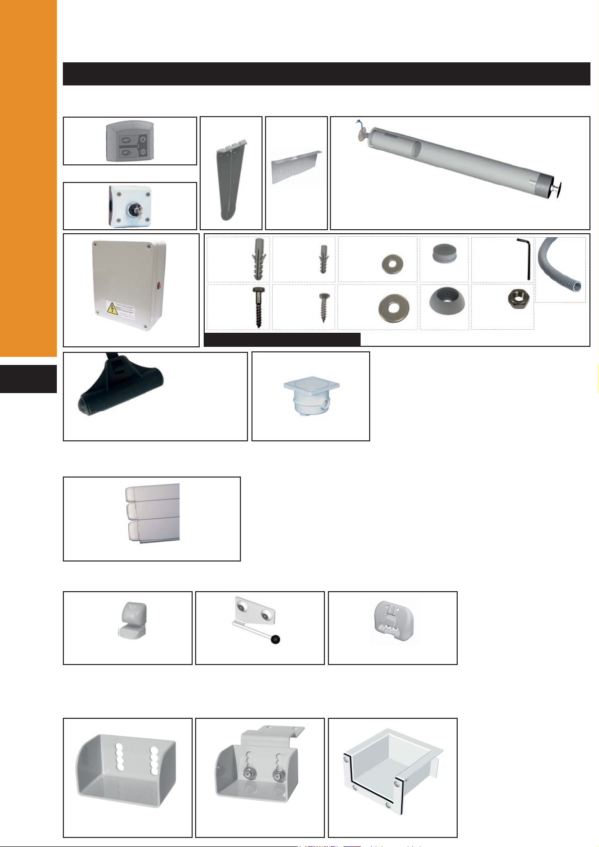
PARTS INCLUDED IN THE DELIVERY
Description
THIS NOTICE MUST BE GIVEN TO THE POOL OWNER
PLEASE READ CAREFULLY AND KEEP IN A SAFE PLACE
Roll-Energy evolution (2 boxes - Supports + Tube)
Slats (model, colour and number of boxes according to your order)
OPTION - Safety locking kit «according to your order» (1 box)
Control box
x1
Template
Spare parts bag
x1x1
Anodised aluminium tube with tubular motor
x8
Screw
M8x80
x8
Sleeve
Ø12
x4
Sleeve
Ø8
x4
Screw
M6x30
x15
Washer
Ø8,4x24
x7
Nut
M8
x1
Allen key
n°4
Quick-Lock
3 fitting models : Surface mounted - Insert mounted - Hanging mounted
Push-lock
Beam support «Model according to your order» (1 box)
69 mm slats
Connection box
«OPTION»
x2
weight
Adjustable quantity accor-
ding to the pool width
x1
1m
x1
Washer
Ø8,4x15
x8 x8
x8
Surface mount Adjustable hanging
mount Insert mount
or

3
Description
NECESSARY TOOLS - (INSTALLATION - 2 PERSONS)
PACKING LIST
example - for a 5 x 10 m pool with Ø3 m step unit
Support + control box : 1 box of 0.65 x 0.45 x 0.25 --- 40 Kg
Tube with motor : 1 box of 0.20 x 5.10 m --- 40 Kg
Aluminum beam : 1 box of 0.15 x 0.15 x 5.10 m --- 40 Kg
Beam support : 1 box of 0.30 x 0.20 x 0.20 m ---10 Kg
Decking : 1 pallet of 1.20 x 1.00 x 0.50 m --- 100 Kg
Slats : 5 box of 0.25 x 0.20 x 5.00 m --- 250 Kg
locking kit : 1 box of 0.30 x 0.20 x 0.20 m or 0.75 x 0.25 x 0.15 m --- 5 KG
Total weight : 485 Kg
Aluminium beam
“Model according to your order” (1 box)
Middle telescopic support
(1 box)
Hanging and surface
mount
Insert mount
support (for pool width > to 6 m)
Decking “Model according to your order” (1 pallet)
Ø8 - 12 - 20
n°10
n°13
n°17
Exotic wood IPE
«OPTION»

4
Information
INFORMATION
For concrete, cellular concrete, full or hollow masonry pools, positioning is identical on the motor
side and the free side.
For polyester and panel pools, forecast concrete reinforcement for the
installation of the supports and safety locking kits.
Quantity of concrete (in litres ) necessary for the supports reinforcement :
Pool surface (m²) x 2.5 = x concrete litres
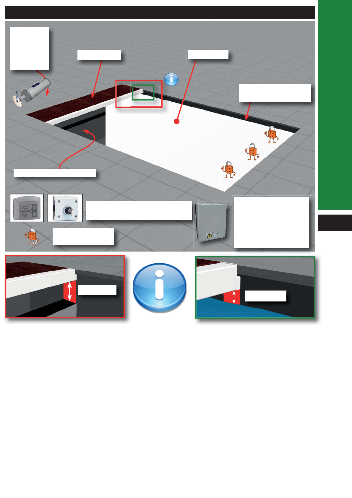
Open pool : the cover is in the cover pit under the decking.
The decking is supported by a beam installed on beam supports.
The depth of the tube is 55cm under the coping stones and is fixed on 2 supports
The mains supply comes from the electric control panel in the plant room.
Automatic stops are adjusted directly on the electric control panel
The switch is located in a dry location with a view on the pool.
The cover is made of watertight floating slats

5
Information
THE IN GROUND COVER
OPTION
Safety locking kits
Gap between the wall
and the cover
Tubular
motor con-
form to
electrical
standards
Decking
Safety wall or Sécuriwall
Control box conform to
electrical standards :
C 15-100
NF EN 60335
NF EN 61000-6-3
NF EN 55014-1
slats
15 cm maxi 4 cm min
Switch with maintained contact
during locking looking at the pool

6
Installation
CHARACTERISTICS AND COVER PIT DIMENSIONS
The sides of the cover pit must be vertical and parallel between them.
The dimension I
(minimum distance of the cover p
i
must be taken at the end of th
e
radius or the cut side.
Concrete separation wall
Main drain
skimmer L = Pool length (step unit and cover pit)
With straight radius or radius and cut sides <= to 10 cm back of the cover pit
With radius and cut sides > to 10 cm back of the cover pit
water level
regulator
Sécuriwall
Sécuriwall
Main drain
skimmer
M
inimum
distance of
the cover
p
i
t
L = Pool length (step unit and cover pit)
water level
regulator
I
M
inimum
distance of
the cover
p
i
t
I
I
L
(en m) < 6 6 à 7 7 à 8 8à9 9à10 10à11 11à12 12à13 13à14 14à15 15 à16 16à17
I
(en mm) 548 574 598 621 643 664 684 703 722 740 758 775
L
(en m) 17à18 18à19 19à20 20à21 21à22 22à23 23à24 24à25 25à26 26à27 27à28 28à30
I
(en mm)
791
mm
807
mm
823
mm
839
mm
854
mm
869
mm
883
mm
897
mm
911
mm
925
mm
938
mm
965
mm

7
Installation
- Fit the template and
mark the position of the
drill holes. Drill holes can
be positioned quickly
using a template.
- The water level must be
below the support screws.
- Clean the drillings.
- If there is water in the pool, put a support on the water (Polystyrene plate) to protect
the water against dusts during the drilling.
TEMPLATE
DRILLING
Ø12
80 mm “minimum”
Straight radius
Radius or cut sides
Sécuriwall
with coping stone
Water
Middle of the template
C + 25 mm C - 25 mm
Water
C + 25 mm C - 25 mm
Water
C = I / 2
C = I / 2
I
I
C + 25 mm
C = I / 2 C - 25 mm
I
eau
i
t)
e

8
Installation
SETTLEMENT OF THE SUPPORTS
Sleeve
Washer
Do not tighten the
screws after the
resistance point, you
could damage the
installation.
Concrete
Once the resistance
point has been
reached, turn the
screws 3 times to
finish the installation.
Washer
Concrete blocks
- Do not carry the tube with the motor’s electrical cable.
- If there is water in the pool, let the tube fill in with water.
Motor side
Do not forget the hole to join the motor’s electrical cable and the connection box. (page 14)
x8
Screw
M8x80
x8
Sleeve
Ø12
x8
x8
Washer
Ø8,4x15
x8
Screw
M8x80
x8
Sleeve
Ø12
x8
Washer
Ø8,4x24
Fixation en façade Fixation cavalier “OPTION”
n°13
n°13
n°13
Ø12
Ø12
x2 x4 x4
x8

9
1
2
3
Installation
Motor side
Free side
Passing the cable through the motor
side plate.
Motor side :
Push the tube so that the motor side is
fitted properly against the wall.
Free side :
Tightening ring
TUBE LEVEL ADJUSTMENT
TUBE INSTALLATION ON THE SUPPORTS
VERTICAL ADJUSTMENT ON THE TUBE / POOL
Adjustment
cover pit
Motor side Free side
x4
x4
Nut
M8
n°13
n°13
x4
x4
Nut
M8
x1
Allen key
n°4
moteur cable
Washer
Ø8,4 x 24
Washer
Ø8,4 x 24

10
Installation
Glue the first gasket of the beam support.
Install the liner.
Install the second gasket, the stainless steel
flange and screw.
Cut the liner inside the beam support with a
cutter.
BEAM SUPPORTS
For concrete pools
Hanging support Washer
Ø10
Screw
inox A4
M10 x 60
Sleeve
Ø12
Nut Inox A4 M10
Ø12
Align the beam support
with the separating wall
15 cm
Max
Cover pit
Cover pit
15 cm
Max
Seal 1
Seal 2
Flange Liner
Screw Insert mount
PVC
Panel settlement :
For concrete or panel pools
Align the beam support
with the separating wall
Nut M8
Washer Ø8
Screw
M8 x 20
Insert mounted model
Adjustable hanging mounted model

11
Installation
Sleeve 12 x 60
Screw TH M8 x 80
Washer
Ø8.4 x 24
Ø12
80 mm “minimum”
Sleeve
Washer
Do not tighten the
screws after the
resistance point, you
could damage the ins-
tallation.
Concrete
Once the resistance
point has been
reached, turn the
screws 3 times to
finish the installation.
Washer
Concrete blocks
For concrete or panel pools and pools with a wall thicker than 8mm
Align the beam support
with the separating wall
15 cm
Max
Cover pit
Surface mounted model

12
+
1
Installation
COVER INSTALLATION
STEP UNIT HOOK INSTALLATION
Allen Key
mâle n°4
Cut out
Box stickered «Début de volet»
Box stickered «escalier»
Install the slats on the water
and clip them together.
Take care with the direction
of the cover over the pool
For pools with a
step unit
Last slat of the step
unit
HOW TO TAKE OFF A SLAT AND END CAPS ?
69 mm slats
with a small screw driver
female
male
top
down
“CLAC”
Fit the slats along
the whole length
Repeated wiggling/handling of the slats may be needed..
Box stickered «fin de volet»

13
Installation
Installation
ALUMINIUM BEAM INSTALLATION
OPTION MIDDLE TELESCOPIC SUPPORT
WEIGHT INSTALLATION
Cover pit side
Middle telescopic
support
For pool over 6 m wide, you need to install 1 or 2 middle telescopic support, to maintain the
beam.
Weights guarantee a better reeling of the cover around the tube and guide the cover. The weight
for the step unit prevents the slats from falling behind the cover pit.
Step unit hook
weight
weight for step unit
900 maxi
1 m 1 m

14
5 cm
ADJUSTMENT OF THE WEIGHT DEPTH
Closed pool
Open pool
Adjust the depth of
the weight
Installation

15
Seal for wooden
decking
DECKING INSTALLATION
Installation

16
12
a
a
abb
b
a*
a*
Installation
ELECTRICAL WIRING / WI-KEY
Connection
Plug N and L
230 VDC
monophased 50 Hz
Salt electrolysis
system
The installation must comply with the C15-100 standards (last version).
Installation in a dry, airy and moderate local.
Circuit breaker
with a 30 mA
protection.
3 x 1,5 mm²
2 x 4 mm² - until 16 m
2 x 6 mm² - from 16 until 25 m
50 cm maxi
a* :
Wire present or
not depending on
the motor type
We recommend applying sealing gel in the connection box aer having completed the wiring.

17
Installation
WI-KEY INSTALLING THE CONTROL BOX
- It must be located in a place from which it is possible to check
that no one enters the pool during the manoeuvre.
- It is mandatory to install the locking «strip».
- Before fixing the control box, check that the emitter is
communicating with the receiver.
The support must be attached to a fixed support
Closing
Opening Stops the current action
Keyboard lock
red / green flashing = emitter locked
Emitter unlocking procedure see «page 30»
The emitter must be located outside volume 0.
The distance between the emitter and the receiver must not exceed:
- 50 m in an obstacle-free zone.
- 25 m behind a basic wall.
- 15 m behind several walls or an especially thick wall.
we recommend checking emitter/receiver communication before fi xing permanently.

18
12
O
F
a
a
abb
b
a*
a*
Installation
ELECTRICAL WIRING WITH KEY OPERATED BOX
Connection
Plug N and L
230 VDC
monophased 50 Hz
Salt electrolysis
system
The installation must comply with the C15-100 standards (last version).
Installation in a dry, airy and moderate local.
Circuit breaker
with a 30 mA
protection.
3 x 1,5 mm²
2 x 4 mm² - until 16 m
2 x 6 mm² - from 16 until 25 m
3 x 1,5 mm²
50 cm maxi
a* :
Wire present or
not depending on
the motor type
We recommend applying sealing gel in the connection box aer having completed the wiring.

20
1
2
ON
OFF
ON
OFF
O
O
O
O
F
F
F
F
F
F
F
F
F
F
F
F
F
F
F
F
F
F
ON
OFF
O
O
O
O
F
F
F
F
F
F
F
F
F
F
F
F
F
F
F
F
ON
OFF
1
2
I
0
II
I
0
II
3
4
Installation
Recording position «open pool»
1 - Programme starting :
Adjust the position of the cover using the programme «open and closed»
check up
Cover installation «open pool»
Cover
opening
Cover
closing
Contact maintained
if the control logic is incorrect, Check the wiring installation
Be careful to choose the right position, it will be the starting reference.
AUTOMATIC STOP ADJUSTMENT (MOTOR DL6010-DL7710)
FORCAGE
PROGRAM
FORCAGE
PROGRAM

21
ON
OFF
O
O
O
O
F
F
F
F
F
F
F
F
F
F
F
F
F
F
F
F
F
F
ON
OFF
O
O
O
O
F
F
F
F
F
F
F
F
F
F
F
F
F
F
F
F
F
F
5
6
7
Installation
Automatic stop adjustment is over.
Recording position «closed pool»
Adjust the position of the cover using the programme «open and closed»
Be careful : the last operation used must be a closing.
«if you cannot close the cover, chek the electric control is correct
and start the automatic stop adjustement procedure from the deginning. »
Cover installation «closed pool»
FORCAGE
PROGRAM
Table of contents
Other DEL Lighting Equipment manuals