Delsys Trigno Avanti FSR Adapter User manual

Trigno®Wireless
Biofeedback System
__
Avanti FSR Adapter
User’s Guide
Copyright © 2019 by Delsys Incorporated
MAN-019-2-1
MP1278B
August 2019
No part of this document may be reproduced, transmitted, transcribed, stored in a retrieval
system, or translated into any language in any form by any means without the written
permission of Delsys Inc.
Download EMGworks® at
www.delsys.com/emgworks

Important Information...............................................................................3
Intended Use...........................................................................................................3
Contraindications ....................................................................................................3
Technical Service and Support ................................................................................ 3
Warnings and Precautions ......................................................................................4
Device Information.................................................................................................. 5
Windows PC Requirements.....................................................................................6
Android Device Requirements................................................................................. 6
Trigno System Overview ............................................................................ 7
Trigno FSR Adapter Features...................................................................................7
Inertial Measurement Unit ................................................................................................ 8
Dual Mode “BLE-Base” Communication ............................................................................ 8
Wireless Communication................................................................................................... 8
Data Synchronization......................................................................................................... 8
Rechargeable Battery......................................................................................................... 8
Sealed Enclosure................................................................................................................ 8
Internal Magnetic Switch ................................................................................................... 8
Sensor LED Feedback States .............................................................................................. 9
Getting Started with the Trigno FSR Adapter ........................................... 11
Configuring the Trigno FSR Adapter ......................................................................11
Using the Analog Outputs (if Equipped)................................................................11
Working with FSR Membranes..............................................................................12
Handling FSR Membranes................................................................................................ 12
Connecting the FSR Membranes to the Adapter.............................................................. 13
Applying the FSR Membrane ........................................................................................... 13
Placing the FSR Adapter................................................................................................... 15
Maintenance and Care............................................................................. 16
Trigno Sensors.......................................................................................................16
Specifications........................................................................................... 17
Physical Specifications...........................................................................................17
Electrical Specifications.........................................................................................17
Inertial Measurement Data Modes....................................................................... 18
Orientation Measurement Data Modes................................................................ 19

Trigno Avanti FSR Adapter User’s Guide 3
Important Information
Intended Use
The Trigno Avanti FSR Adapters are components of the Trigno® Wireless
Biofeedback System. This system is a battery-powered biofeedback device that
enables researchers and clinicians to acquire EMG and related signals from
subjects for biofeedback and research purposes. The System is intended for
relaxation training and muscle reeducation. Interpretation of the EMG and
supporting signals by a qualified individual is required.
Rx ONLY
Contraindications
DO NOT USE on Patients with implanted electronic devices of any
kind, including cardiac pace-makers or similar assistive devices,
electronic infusion pumps, and implanted stimulators.
DO NOT USE on irritated skin or open wounds.
DO NOT USE on Patients with allergies to Silver.
DO NOT USE in critical care applications.
Technical Service and Support
For information and assistance please visit our web site at:
www.delsys.com
Contact us at:
Telephone: (508) 545 8200

4 MAN-019-2-1
Warnings and Precautions
Consult all accompanying documents for precautionary statements and
other important information.
Consult accompanying user’s guide for detailed instructions.
Keep the device dry. The ingress of liquids into the device may compromise
the safety features of the device.
Handle with care.
Sensitive electronic device. Avoid static discharges. Do not operate or store
near strong electrostatic, electromagnetic, magnetic or radioactive fields.
Interference from external sources may decrease the signal-to-noise ratio
or result in corrupted data.
Connect only to Delsys-approved devices.
Connecting a patient to high-frequency surgical equipment while using
Delsys EMG systems may result in burns at the site of the EMG sensor
contacts
Immediately discontinue device use if skin irritation or discomfort occurs.
Immediately discontinue device use if a change in the device’s
performance is noted. Contact Delsys technical support for assistance.
Delsys Inc. guarantees the safety, reliability, and performance of the
equipment only if assembly, modifications and repairs are carried out by
authorized technicians; the electrical installation complies with the
appropriate requirements; and the equipment is used in accordance with
the instructions for use.
Device contains a Lithium-Polymer battery. Do not damage, crush, burn,
freeze or otherwise mishandle the device. Recharge only with the
approved power supply and recharger.
Report any serious incidents with the device to Delsys at 508 545 8200 or
Trigno Systems should be stored and operated between 5 and 45 degrees
Celsius due to the presence of an internal Lithium Polymer rechargeable
cell. Storing or operating the device, and consequently the cell, outside of
this temperature range may compromise the integrity and the safety
features of the cell.

Trigno Avanti FSR Adapter User’s Guide 5
Device Information
Complies with Requirements put forth by the Medical Device Directive
93/42/EEC. Class I device, Annex VII. Type BF device (IEC 60601-1)
Isolated device, (Class II, IEC 60601-1)
Type BF Equipment.
Date of Manufacturing (appears on device)
Manufacturer:
Delsys Inc.
23 Strathmore Rd.
Natick, MA, 01760, USA
Serial Number (appears on device)
Dispose the device according to local rules for electronic waste.
Authorized Representative:
EMERGO EUROPE
Prinsessegracht 20, 2514 AP The Hague
The Netherlands
Trigno Wireless Biofeedback System
Sensor Model: SP-W06-020 (“Trigno Avanti FSR Adapter”)
System Model: DS-T03
FCCID: W4P-SP-W06 (Sensor)
FCCID: W4P-SP-W02 (Base Station)
IC: 8138A-DST03 (System)
211-190332 (DS-T03)
211-190333 (SP-W06)
This device complies with Part 15 of the FCC Rules and Industry Canada’s
RSS-210 License Exempt Standards. Operation is subject to the following
two conditions: (1) This device may not cause harmful interference. and (2)
this device must accept any interference received, including interference
that may cause undesired operation.
This Class B digital apparatus complies with Canadian ICES-003.
Cet appareil est conforme à des règlements d'Industrie Canada exempts
de licence standard RSS (s). Son fonctionnement est soumis aux deux
conditions suivantes: (1) Ce dispositif ne doit pas causer d'interférences
nuisibles, et (2) cet appareil doit accepter toute interférence reçue, y
compris les interférences pouvant entraîner un fonctionnement
indésirable.

6 MAN-019-2-1
Cet appareil numériqué de la classe B est conformé à la norme NMB-003
du Canada
This product complies with FCC OET Bulletin 65 radiation exposure limits
set forth for an uncontrolled environment.
To reduce potential radio interference to other users, the antenna type
and its gain should be so chosen that the equivalent isotropically radiated
power (EIRP) is not more than that required for successful communication.
This equipment has been tested and found to comply with the limits for a
Class B digital device, pursuant to Part 15 of the FCC Rules. These limits are
designed to provide reasonable protection against harmful interference in
a residential installation. This equipment generates, uses, and can radiate
radio frequency energy and, if not installed and used in accordance with
the instructions, may cause harmful interference to radio communications.
There is no guarantee that interference will not occur in a particular
installation. If this equipment does cause harmful interference to radio or
television reception, which can be determined by turning the equipment
off and on, the user is encouraged to try to correct the interference by one
or more of the following measures: Reorient or relocate the receiving
antenna; increase the separation between the equipment and receiver;
Connect the equipment into outlet on a separate circuit.
Pursuant to FCC 15.21 of the FCC rules, changes not expressly approved by
Delsys Inc. could void the User’s authority to operate the equipment.
Please refer to the main Trigno System User Guide for additional
information.
Windows PC Requirements
•EMGworks 4.7 or later
•Windows 7, 8.1, 10
•One USB 2.0 port
•At least 2.0 GHz processor clock speed
•At least 2 GB system memory
•1280x1024 (SXGA) display resolution or better
•50 GB hard disk storage (minimum)
Android Device Requirements
•Android V 7 (Nougat) operating system or later
•BLE 4.2 support
•RAM 1GB minimum
•Storage 8 GB minimum
•Screen Resolution 2048x1536 (recommended)
•Recommended Tablet:
Samsung Galaxy Tab S2
8”screen, 32 GB, WI-FI
(SM-T713NZKEXAR)
or
Samsung Galaxy Tab S5e
10.5" AMOLED screen, 64 GB Storage
Android 9.0 (Pie), WiFi & Bluetooth v.5.0

Trigno Avanti FSR Adapter User’s Guide 7
Trigno System Overview
The Trigno® Avanti FSR Adapter is component of the Trigno Wireless
Biofeedback System, and is designed to provide relative pressure information
of body-contact surfaces, such as the heel, the toe and the fingers. Three FSR
membrane sizes are available for optimizing performance in varieties of
scenarios. Data are expressed as a percentage of the sensor’s full scale limits.
These devices are useful for identifying the timing of significant events and for
making relative amplitude comparisons of pressure, but are not suitable for
making absolute measurements of force or pressure. The system transmits
signals from the Trigno sensors to a receiving base station using a time-
synchronized wireless protocol which minimizes data latency across sensors.
For mobile biofeedback applications, Trigno Sensors can communicate with
Bluetooth BLE 4.2 compliant host devices. The system is also capable of
integrating with 3rd party lab equipment through a variety of interfaces which
include analog signal generation, triggering scenarios and digital integration
through the Trigno SDK (Software Development Kit) and the Trigno API
(Application Program Interface).
Refer to the Trigno System User Guide for System information and
operational details.
Trigno FSR Adapter Features
The Trigno FSR Adapters are capable of detecting pressure disturbances using
industry-standard force sensitive resistors (FSRs). Each Sensor is equipped with
the following capabilities and design features:
•4 FSR channels
•Compatible with Interlink Electronics 0.2”, 0.5” & 1.5” FSR sensors
•bandwidth DC-50 Hz.
•Built-in 3DOF IMU (accelerometer, gyroscope, magnetometer)
•onboard orientation calculation
•inter-sensor latency < 1 sample period
•wireless transmission range 20+m1
•self-contained rechargeable battery
•battery charge monitoring and status indicator
•environmentally sealed enclosure
•low power mode
•auto shutoff
•internal magnetic switch
•LED User Feedback
1
. Communication distance is dependent on the RF operating environment.

8 MAN-019-2-1
Inertial Measurement Unit
Trigno sensors have a built-in 9 DOF inertial measurement unit which can relay
acceleration, rotation and earth magnetic field (compass) information. Users
can use this information to discern movement activity time-synchronized with
the EMG signals. One of 4 ranges can be selected for each sensor to span ±2g
to ±16g for accelerometer outputs and ±250°/s to ±2000°/s for gyroscope
outputs. The sensor is capable of estimating orientation in 3D space from the 9
channels of information.
Dual Mode “BLE-Base” Communication
Trigno sensors are capable of communication with a PC-connected Base station
using the Trigno custom wireless communication protocol, or with Android
devices using the Bluetooth Low Energy (BLE) industry standard protocol. Note
that the information bandwidth when operating over Bluetooth is limited by
the Bluetooth protocol and the host device capabilities.
Wireless Communication
The Trigno wireless communication scheme offers robust data transmission for
up to 16 Trigno sensors operating in full bandwidth mode, with a nominal
distance of 20m. Under optimal environmental conditions (no RF path
obstructions or interfering sources), this nominal distance can be notably
superseded.
Data Synchronization
Data from each sensor and from each channel within a sensor are time
synchronized over the Trigno wireless communication protocol so no time skew
between data exists. A maximum of 16 sensors can stream data to a host base
station at one time. These features are available only when communicating with
the PC-connected Base Station; the Bluetooth/BLE protocol does not guarantee
latency.
Rechargeable Battery
Sensors contain a sealed rechargeable lithium polymer battery for continuous
use which can be extended when making use of low power modes. Actual
duration will depend on usage conditions, which are expected to vary between
4 to 8 hours of performance. Charge status is conveniently reported through
the wireless communication protocol.
Sealed Enclosure
The environmentally sealed enclosure protects the electronics from the ingress
of liquids and other environmental elements and provides a high standard of
user safety and durability.
Internal Magnetic Switch
The Trigno sensors are equipped with an internal magnetic switch which is used
to turn the sensors “on” and to perform RF pairing operations. To activate the
internal magnetic switch, the sensor must be placed on the magnet lock label

Trigno Avanti FSR Adapter User’s Guide 9
located on the Base Station charging cradle. The internal magnetic switch will
only react when the sensors are undocked from the charger or when the
software is performing an RF pairing operation. Exposure to any magnetic fields
outside of these 2 qualifying conditions will be ignored by the sensor. The
internal magnetic switch is a feature which removes the need for a mechanical
button and improves sensor durability and performance. Common household
magnets can be used to perform these functions as well.
Sensor LED Feedback States
Trigno Avanti sensors indicate their status through various LED Arrow colors
and blink patterns as indicated in the table below. Each of these states is
described in subsequent sections of this User Guide.
State
Color
Pattern
Arrow Display
Common States
1
Power Off
Off
none
2
Power On/Activate
White/Green
fade
/
3
Charging
Amber
solid
4
Charge Complete
Green
solid
5
Identification Mode
White
rapid flash
/ /
6
Scan (Startup)
Amber/Cyan
slow flash
/
7
Power Up Error
Red
slow flash
/
Trigno RF Mode
8
Scan (Base)
Amber/Green
Slow flash
/
9
Low Power Scan (Base)
Amber
Occasional Flash
/
10
Data Collection (Base)
Green
slow flash
/
11
Configuration Change (Base)
Green
rapid flash (3x)
/ /
12
Pairing (Base)
Amber
solid
13
Pairing Success (Base)
Green
rapid flash (≥6x)
/ /
/ /
14
Pairing Fail (Base)
Red
double flash(≥3x)
/ /
BLE Mode
15
Advertise (BLE)
Cyan
Slow flash
/
16
Low Power Advertise (BLE)
Cyan
occasional flash
/
17
Data Collection (BLE)
Blue
slow flash
18
Idle (BLE)
Magenta
slow flash
Table 1: Sensor LED functions.

10 MAN-019-2-1
LED State Descriptions
1) Power Off: No LED arrow activity is present when the sensor is off.
2) Power On: When undocked, the sensor illuminates white and fades to
black. A magnetic field will turn the sensor on within 6 seconds, otherwise
the arrow fades to dark and sensor turns off.
3) Charging: Sensor Charging in the Trigno Base Station is denoted by
continuous amber LED arrow illumination
4) Charge Complete: Once the internal sensor battery has been fully
recharged, the LED arrow illuminates to continuous green.
5) Identification Mode: The arrows blink white upon this software command
so that it can be easily identified and located.
6) Startup Scan: upon power-up the sensor actively searches for a host to
connect to (PC Base Station or BLE tablet).
7) Power Up Error: Sensor fails self-check on power up
8) Scan (Base): Sensor was previously paired and is scanning for the active
base station.
9) Low Power Scan (Base): Sensor was previously paired and has been
scanning for the active base station for more than 5 minutes.
10) Data Collection (Base): Data from sensor are streaming to a paired PC-
connected base station.
11) Configuration Change (Base): Sensor acknowledges change in
configuration sensor from host base station.
12) Pairing (Base): Sensor is performing a pair operation with the base host.
13) Pairing Success (Base): Sensor successfully completes a pair operation with
the Base Station host.
14) Pairing Fail (Base): The pair operation did not complete successfully with
the Base Station host.
15) Advertise (BLE): Sensor is broadcasting to connect with a BLE host.
16) Low Power Advertise (BLE): Sensor is broadcasting to connect with a BLE
host for more than 5 minutes.
17) Data Collection (BLE): Sensor is sampling and streaming data to BLE host.
18) Idle (BLE): Sensor is waiting for a Bluetooth BLE command.

Trigno Avanti FSR Adapter User’s Guide 11
Getting Started with the Trigno FSR Adapter
Please refer to the Trigno System User guide for key
operational details regarding the base station, sensor charging,
and initiating the sensor.
Configuring the Trigno FSR Adapter
Once paired to the system, FSR data and optionally IMU data from the sensor
can be configured through the software in the following ways:
FSR Channel Characteristics
Input Range
0 ohms to open circuit
Bandwidth
DC-50 Hz
Inertial Measurement Unit (IMU) Ranges
Accelerometer1
±2 g
or
±4 g
or
±8 g
or
±16 g
Accelerometer Bandwidth1
24Hz - 470 Hz
Gyroscope1
±250 dps
or
±500 dps
or
±1000 dps
or
±2000 dps
Gyroscope Bandwidth1
24 Hz - 360 Hz
Orientation2
10 Hz
1Accelerometer and gyroscope range, bandwidth and sampling rate are configured by
the software.
2Note that the orientation is calculated on-board with a data fusion algorithm.
Using the Analog Outputs (if Equipped)
The Trigno System provides simultaneous analog signal reconstruction of data
being detected by all active sensors. These signals are made available on the
68-pin connectors located on the Base Station and range cover the +/-5V range.
Analog outputs are engaged through software and are only available for specific
sensor sampling configurations as stated below:
Sampling Rate
Data Type
Bandwidth
Ch. x.1
1926 sa/sec
FSR A
20-450 Hz
Ch. x.2
148 sa/sec
FSR B
DC-50 Hz
Ch. x.3
148 sa/sec
FSR C
DC-50 Hz
Ch. x.4
148 sa/sec
FSR D
DC-50 Hz
Table 2: Analog Output signal details. Note that sampling rates are approximate; please
refer to specification table for precise sampling periods.

12 MAN-019-2-1
Figure 1: Analog Output Data Flowchart
Refer to the Trigno System User Guide for more information on Analog Output
Operation.
Working with FSR Membranes
Handling FSR Membranes
The FSR membranes are delicate transducers constructed in multiple layers that
have an ability to change resistance as pressure is applied. Delsys supplies
these membranes with a 30 cm cable extension, terminated with a shrouded
barrel connector for mating with the wireless adapter. Care must be exercised
when using these membranes as excessive forces will damage them. These are
particularly vulnerable to shear forces, such as those encountered during
walking or running, which may cause the membrane to delaminate. It is
recommended to place the membrane in a protected location where its
exposure to these forces is limited. Alternatively, the FSR membrane can be
protected by layering it between two pieces of clear vinyl packaging tape. In
this case, care must be taken to ensure that the air channel at the membrane
edge is not occluded and remains clear.
Figure 2: Ensure that the air channel at the joint of the membrane and the cable remains
clear so that air can flow during membrane compressions.
Trigno Avanti FSR Adapter User’s Guide 13
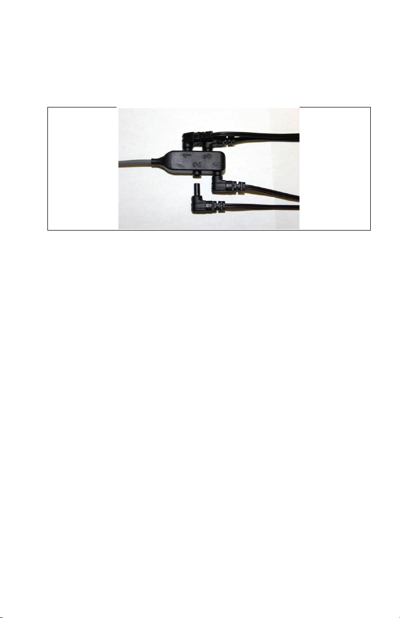
Connecting the FSR Membranes to the Adapter
The Trigno FSR Adapter has a connector head hosting 4 receptacles for the
membrane transducers. Connect the FSR membranes by to the 4 barrel
receptacles taking care to fully mate the plug. The connectors are labeled
numbers 1-4 on the sensor, and portrayed in this order in the EMGworks
software. All FSR membranes are interchangeable.
Figure 3: Mating the FSR membrane connectors to the sensor connector head. Ensure
that the barrels are fully inserted.
Applying the FSR Membrane
The FSR membranes can be used in a wide variety of circumstances and
applications; thus each case must be evaluated for any particular challenges it
may pose. One common application of this device is to use it as footswitch
during walking or running. With this example, one can consider several
options for affixing the sensor to the heel, as shown in the figures below. Taping
the sensor directly to the heel will produce a very sensitive and responsive
signal. However this approach subjects the FSR membrane to high load and
shear forces, which may cause signal saturation and accelerated wear.
Protecting the FSR membrane with tape or similar material can be done to
extend usage life.
An alternative approach to affixing the FSR membrane to the heel, is to
instrument the shoe by taping it to the sole. This will produce a similar response
as the previous example, but may offer some added convenience for repetitive
data trails. Applying tape to the FSR membrane may extend its usage life.

14 MAN-019-2-1
Figure 4: Affixing the FSR membrane to the top of the inner sole.
Placing the FSR membrane on the bottom of the inner shoe sole, provides some
added protection to the device, as load and shear forces are diffused between
the show base and the sole. This location may also be convenient to avoid signal
saturation in cases of high loads.
Figure 5: Affixing the FSR membrane to the bottom of the inner sole.
The examples above serve to illustrate common techniques that Re-searchers
employ when using FSR type devices. Each situation and use-case is unique,
however, so the User is encouraged to explore other strategies as needed.
The 3 supported FSR membrane size can be used in a wide range of applications
which can include activities such as sitting, walking, lying down, jumping,
fingertip contact and many others.

Trigno Avanti FSR Adapter User’s Guide 15
Figure 6: FSR membrane options for varieties of applications servicing 5 mm2, 15 mm2
and 40 mm2 areas.
Since each FSR sensor can support up to 4 channels, it is possible to observe 4
pressure points with 1 sensor. Continuing with the previous example of
monitoring footstrike at the heel, one could add three additional monitoring
points to the 1st metatarsal, the 5th metatarsal and the toe, resulting in a
well-characterized contact point map of the foot.
Figure 7: Mapping 4 pressure points of the foot. Left panel shows the location of the 4
pressure points being monitored. Middle panel shows data from these during low
intensity running on a treadmill as acquired by EMGworks. Right panel expands the time
scale for 1 foot strike, showing the time-course and relative intensity of each pressure
point.
Placing the FSR Adapter
The Trigno FSR Sensor and the associated connection head can be easily affixed
to the surface of the body using the Delsys Adhesive interfaces. The
connector head is easily serviced by cutting a full-size interface in half.
Additional self-adhesive wraps or tapes can be used to further secure the sensor
on the body.

16 MAN-019-2-1
Maintenance and Care
Trigno Sensors
Trigno sensor are encased in a sealed polycarbonate enclosure. The following
points should be kept in mind when handling the sensors.
•All sensors should be visually inspected before each use to ensure that
no mechanical deterioration has occurred.
•The sensors can be cleaned with isopropyl alcohol swabs. Ensure that
the sensor contacts remain clean at all times for proper operation.
•While the sensors are sealed and are water-resistant, these should
never be completely submerged in any liquid.
•Sensor leads are delicate and should be handled gently. Do not pull,
kink or twist leads as damage may occur.
Handle the sensors with care: do not drop them on the ground or
step on them.
Do not submerge the sensors in any liquid under any circumstance.
Do not pull the cable as this will result in damage.
The sensors contain sensitive electronic circuitry. Static discharges
and intense electro-magnetic fields should be avoided to prevent the
risk of irreparable damage to the sensors.

Trigno Avanti FSR Adapter User’s Guide 17
Specifications
Physical Specifications
Dimension (Body)
27 x 46 x 13 mm
Cable Length
102mm
Mass
25g
Temperature Range(1)
5 - 45 degrees Celsius
1) Exposure beyond these temperature limits may damage the rechargeable battery.
Electrical Specifications
RF Frequency Band
2400-2483 MHz (ISM band)
FSR Resistance Range
180 –300000 ohms
Dynamic Range
0 ohms –open circuit
Accelerometer Range
±2g, ±4g, ±8g, ±16g
Accelerometer Bandwidth
50 Hz –246Hz (configurable in software)
Gyroscope Range
±250 dps, ±500 dps. ±1000dps, ±2000dps
Gyroscope Bandwidth
50 Hz –361 Hz (configurable in software)
Magnetometer Range
±4900 uT
Magnetometer Bandwidth
50 Hz
Inter-Sensor Delay
< 1 sample period (Base Station only)
Intra-Channel Delay
< 1-2 sample period

18 MAN-019-2-1
Inertial Measurement Data Modes
Configuration ID
# Data Slots1
# FSR Channels
FSR Sampling Period2(ms)
FSR Sampling Rate2(sa/sec)
FSR Channel Bandwidth3(Hz)
FSR Resolution Depth4(bits)
ACC Sampling Period2(ms)
ACC Sampling Rate2(sa/sec)
ACC Bandwidth5(Hz)
ACC Range6(g)
ACC Resolution4(bits)
Gyro Sampling Period2(ms)
GYRO Sampling Rate2(sa/sec)
GYRO Bandwidth5(Hz)
Gyro Range7(dps)
Gyro Resolution4(bits)
1
1
4
3.375
296
DC-50
16
6.75
148
50
±2
±4
±8
±16
16
6.75
148
50
±250
±500
±1000
±2000
16
2
1
4
27 / 14
519
DC-50
16
--
--
--
--
--
--
--
--
--
--
3
4
4
0.90
1111
DC-50
16
1.35
741
246
±2
±4
±8
±16
16
1.35
741
361
±250
±500
±1000
±2000
16
4
1
1
3
27 / 52
6.75
1926
148
DC-50
16
10
--
--
--
--
--
--
--
--
--
--
5
1
0
--
--
--
--
2.7
370
111
±2
±4
±8
±16
16
2.7
370
152
±250
±500
±1000
±2000
16
1)
The Trigno System is designed with 16 data slots for wireless transmission. Sensors can occupy up to 4 slots
depending on the sampling rate settings.
2)
Sampling period is the precise time elapse between samples in milliseconds. The sampling rate is a rounded
expression of 1/”sampling period” expressed as samples/second (sa/sec).
3)
Analog Butterworth filter bandwidth:2 pole low pass corner in Hz.
4)
sensor resolution depth across input range.
5)
IMU bandwidth determined by onboard digital low pass filter
6)
Accelerometer signal input range in “g” (i.e. 9.8 m/s2)
7)
Gyroscope angular rate input range in degrees per second (dps).
Denotes raw FSR signal acquisition.
Denotes onboard 3 DOF accelerometer data.
Denotes onboard 3 DOF gyroscope data.
Denotes analog output supported mode.
Trigno Avanti FSR Adapter User’s Guide 19
Orientation Measurement Data Modes
Configuration ID
# Data Slots1
FSR Sampling Period2(ms)
FSR Sampling Rate2(sa/sec)
FSR Bandwidth3(Hz)
FSR Resolution Depth4(bits)
Orientation Sampling Period2(ms)
Orientation Sampling Rate2(sa/sec)
Orientation Resolution 8(bits)
5
1
2.7
370
DC-50
16
13.5
74
32
1)
The Trigno System is designed with 16 data slots for wireless transmission. Sensors can occupy up to 4 slots
depending on the sampling rate settings.
2)
Sampling period is the precise time elapse between samples in milliseconds. The sampling rate is a rounded
expression of 1/”sampling period” expressed as samples/second (sa/sec).
3)
Analog Sensor Butterworth filter bandwidth: 2 pole low pass corner in Hz.
4)
FSR sensor resolution depth across input range.
5)
Orientation vector output resolution in bits. Orientation is expressed in quaternions and is performed on the sensor
using a fusion algorithm that combines the accelerometer, gyroscope and magnetometer data.
Denotes raw FSR signal acquisition.
Denotes onboard calculation of orientation fused from 3 DOF accelerometer, 3 DOF gyroscope and 3 DOF magnetometer data.
This manual suits for next models
2
Table of contents
Popular Medical Equipment manuals by other brands


Getinge
Getinge Arjohuntleigh Nimbus 3 Professional Instructions for use

Mettler Electronics
Mettler Electronics Sonicator 730 Maintenance manual

Pressalit Care
Pressalit Care R1100 Mounting instruction

Denas MS
Denas MS DENAS-T operating manual

bort medical
bort medical ActiveColor quick guide

AccuVein
AccuVein AV400 user manual


