Delta Controls DNT-T103 User guide

Document Edition 4.1 Page 1 of 41
A
PPLICATION
G
UIDE
Delta Network Thermostat: BACstat II
DNT-T103 & DNT-T221
Document Edition 4.1
Product Description
The DNT-T103 and the DNT-T221 are intelligent room thermostats with
custom 3-value, 96 segment, LCD displays. The DNT products can
communicate directly on a BACnet MS/TP network or Delta’s proprietary
LINKnet network.
They are capable of displaying a wide-range of digital or analog values,
including setpoints, temperature, air flow, heating and cooling status, fan
speed, valve and damper position, and more. When connected on a BACnet
MS/TP network the DNT-T103 and T221 function as independent BACnet
thermostats. When connected to a Controller on a LINKnet network they
provide programmable remote sensor and expanded I/O capabilities. This
version’s firmware can be flash loaded over the network, and have
termination resistors that are jumper selectable.
The DNT-T103 has 1 extra input, 3 binary outputs and a number of built-in application control strategies. The
DNT-T221 has 2 extra inputs, 2 analog and 1 binary output and built-in application control strategies. As a
result, these BACstats are capable of stand-alone control when directly connected on an MS/TP network.
Contents OTHER RELEVANT DOCUMENTS..................................................................................................2
IMPORTANT INFORMATION ..........................................................................................................2
SETUP &CONFIGURATION.............................................................................................................2
NETWORK COMMUNICATIONS ...........................................................................................................2
DEVICE CONFIGURATION (KEYPAD)..................................................................................................2
SERVICE TOOL MODE (KEYPAD) .......................................................................................................7
INPUT CALIBRATION..........................................................................................................................8
INPUT SCALE RANGES ......................................................................................................................8
SOFTWARE &PROGRAMMING......................................................................................................9
OBJECTS............................................................................................................................................9
PROGRAMMING ...............................................................................................................................12
CONTROL FUNCTIONS...................................................................................................................12
OVERVIEW ......................................................................................................................................12
SOFTWARE LOOP CONTROLLER .......................................................................................................15
SETPOINTS ......................................................................................................................................18
CONTROL DIAGRAM ........................................................................................................................19
CONTROL APPLICATIONS (MUX,VAV, VVT, HPU, FCU, RAD,HUM)............................................20
OUTP UT FUNCTIONS &TYPES.........................................................................................................28
OWS FUNCTIONS..............................................................................................................................33
APPENDIX A: PROGRAMMING NOTES....................................................................................................31
APPENDIX B: LINKNET.........................................................................................................................32

DNT-T103 & DNT-T221 Application Guide
Page 2 of 41 Document Edition 4.1
Other Relevant Documents
•Associated BACstat II Installation Guide (DNT-T103 or DNT-221)
•
•
Delta Controls Wiring and Installation Guidelines
•
ORCAview Operator Guide
•Release Notes for relevant firmware and BACstat products
ORCAview Technical Reference Manual
Important Information
This document has been updated to include features and capabilities of Release 4 firmware and
hardware for the BACstat II DNT-T103 and the DNT-T221 products. Although BACstat firmware is
independent from ORCAview, DCU, and Application Controllers, certain BACstat capabilities
require support in the other products. The firmware for the DNT-T103 and the DNT-T221 can be
flash loaded over the network.
1. V3.22FIRMWARE &SOFTWARE OR HIGHER
When BACstats are used with ORCAview, DCU, and Application Controllers loaded with V3.22
firmware/software please be aware of the following issues.
For an MS/TP Network Connection:
•A DSC is required
•Local BACstat display handling and control strategies may be enabled
•Data exchange may be done in GCL+ programming in any DCU or Application Controller
on the MS/TP network
Setup & Configuration
NETWORK COMMUNICATIONS
On an MS/TP network BACstats communicate at a default speed of 76,800 bps. Refer to the
Technical Reference Manual for further detail on configuring the MS/TP network or changing
baud rates. Also refer to the associated BACstat II Installation Guide for network installation
details.
Flash Programming
The BACstat II Release 4 product now offers flash loadable firmware across its network
connection. It is supported by Flashloader V3.33, and operates the same way as other Delta
controllers. Please ensure that all the databases have been backed up prior to upgrading the flash
firmware. Refer to the Flashloader V3.33 User's Guide
DEVICE CONFIGURATION (KEYPAD)
for further details on using the
Flashloader to upgrade the firmware on the BACstat II Release 4 product.
To use ORCAview OWS to configure BACstats refer to OWS Functions on page 33.
1. CONFIGURATION MENU USER ACCESS
Access to the Configuration Menu is protected by an access code or PIN. You must enter the valid PIN
before access is granted, which works as follows:
•First press the Up Arrow ( ▲), and then press the Down Arrow (▼) while still pressing the Up
Arrow, and hold them both down for at least 5 seconds.

Delta Controls
Document Edition 4.1 Page 3 of 41
•When the
•The default PIN is 1011. The PIN access code, contained in AV31, can be changed through the
OWS when the BACstat is connected to an MS/TP network.
text is displayed you are being prompted for the valid PIN or access code, a pre-
configured
4-digit code, which you must enter before you can gain access to the Configuration Menu. The
buttons on the left side of the BACstat have a value of 0, while the buttons on the right side have a
value of 1. Press the proper button sequence to match the password.
•Once you have entered the valid 4-digit code you will gain access to the Configuration Menu, and
•If at any time after you have gained access to the Configuration Menu you do not press a button for
2 minutes, the BACstat will exit the Configuration Menu and return to normal display mode.
will be displayed immediately to indicate you are now in Configuration mode. If you haven’t
entered a valid code (or if you do not press a button within about 10 seconds), the process will be
aborted and you will be returned to normal display mode.
2. BUTTON &NAVIGATION FUNCTIONS
The Button functions are as follows within the Configuration Menu:
Button Description
Top Left •Represents a value of 0 when entering the PIN access code.
•PREVIOUS: Enter the current setting (and go backward in the menu).
Top Right •Represents a value of 1 when entering the PIN access code.
•NEXT: Enter the current setting (and go forward to the next item in the menu).
Bottom Left
(Down: ▼) •Represents a value of 0 when entering the PIN access code.
•Rotates downward through menu items and options.
•Decreases a numeric value with each button press.
Bottom Right
(Up: ▲) •Represents a value of 1 when entering the PIN access code.
•Rotates upward through menu items and options.
•Increases a numeric value with each button press.
Use the NEXT and PREVIOUS buttons to navigate through the menu options. Once you have navigated to
the desired item you wish to display or change, use the arrow buttons to make any necessary changes.
Once the changes are made or you wish to move on, press NEXT orPREVIOUS.

DNT-T103 & DNT-T221 Application Guide
Page 4 of 41 Document Edition 4.1
3. CONFIGURATION MENU OPTIONS
The Configuration Menu is a list of items that you can navigate through to make changes for setup
purposes. The Configuration Menu items are as follows:
Menu Item Description
Displayed momentarily to indicate you have successfully entered the Configuration
Menu.
[Application] The Control Application (AV12). You may choose from any of the following
applications:
•
•
This disables all control strategies and allows the outputs and control
icons to be controlled remotely from another device.
•
This enables the VAV control strategy and allows you to configure the
outputs for your VAV application.
•
This enables the VVT control strategy and allows you to configure the
outputs for your VVT application.
•
This enables the HPU control strategy and allows you to configure the
outputs for your Heat Pump Unit application.
•
This enables the FCU control strategy and allows you to configure the
outputs for your Fan Coil Unit application.
•
This is no longer an option. Configure control for a Unit Heater using
the FCU application.
•
This enables the Radiation control strategy and allows you to configure
the outputs for your Radiant Heating application.
This enables the Humidity control strategy and allows you to configure
the outputs for your Humidity application.
Available when the Application = VAV. The air flow units setting (CFM or LPS)
Output 1 Configuration. This includes the output function and type (what it will
control and how) and other setup parameters as required (such as delays or limits).
Output 2 Configuration. This includes the output function and type (what it will
control and how) and other setup parameters as required (such as delays or limits).
Output 3 Configuration. This includes the output function and type (what it will
control and how) and other setup parameters as required (such as delays or limits).
[More] Additional parameters to set, which are dependent on the Application and Output
Configuration, may include:
•
•
Actuator Runtime in seconds (AV24)
•
Air Flow Factor for VAV only (AV25)
•
Minimum Air Flow for VAV and Damper Minimum for VVT (AV26)
Maximum Air Flow for VAV and Damper Maximum for VVT (AV27)
The Temperature Units Setting (degrees C or F).
[Settings] Additional control settings, which are particularly useful when an Application is
selected for local control, typically include:
•
Day Setpoint (AV6) •
•
Max. Day Setpoint (AV8)
Day Differential (AV9) •
•
CO Proportional Band (AV19)
Min. Day Setpoint (AV7) •
CO Reset Rate (AV20)

Delta Controls
Document Edition 4.1 Page 5 of 41
Menu Item Description
The LCD Display Code Setting (AV15), a 4-digit value (ABCD) configures local
display and button handling as follows:
A Line 1 (Top Left – i.e., Outside Value): 1 to 4
1- Disabled
2- Value from AV5 (i.e., remote value such as OAT)
3- Value from AI2 (i.e., external sensor)
4- Value from AI3 (i.e., Humidity)
B Line 2 (Center – i.e., Inside Value): 1 to 4
1- Disabled
2- Temperature from AI1
3- Humidity from AI3
4- Alternates between Temperature (AI1) & Humidity (AI3)
5- Value from AI2 (i.e., external sensor)
6- Value from AV5 (i.e., remote value
7- Setpoint
8- Setpoint with adjust
9- User Setpoint with adjust (-3 to +3 degrees)
C Line 3 (Bottom – i.e., Setpoint Value): 1 to 5
1- Disabled
2- No Setpoint until an arrow button is pressed (adjustable)
3- Setpoint is always displayed (adjustable)
4- No Setpoint until an arrow button is pressed (not adjustable)
5- Setpoint is always displayed (not adjustable)
6- Temperature from AI1
7- Value from AI2
8- Humidity from AI3
9- Value from AV5
D House & Day/Night Mode Icons: 1 to 9
HOUSE OUTLINE ON/OFF TEXT MAN SUN/MOON
1 No No No No
2 No Flash No No
3 No Yes No No
4 No No No Yes
5 Yes No No No
6 Yes Yes No No
7 Yes Yes Yes No
8 Yes No Yes No
9 Yes No No Yes
NOTE: When connected to MS/TP, the Display Code may be set to any valid value –
making it unnecessary to write GCL+ programs for display and button handling.
Whenever an application is selected, a matching default Display Code is also set
automatically (typically 1237), but this can be set to something else if so desired.

DNT-T103 & DNT-T221 Application Guide
Page 6 of 41 Document Edition 4.1
Menu Item Description
The Service Tool Mode access setting (AV32) has the following options:
0 Disables all access to Service Tool Mode
1 Provides limited access for VAV, or full access for other applications
2 Provides full access with advanced Air Balancer functions for VAV
Time Clock feature allows the ability for a signal from an external source to directly
control Alg Mode (AV13) via IP2. This feature is only available in non-VAV
algorithms. The Time Clock is enabled by setting the units of AI2 to “Day” or by
selecting for the option in the configuration menu.
IP2 Alg Mode
Short Occupancy
0 Unoccupied
Open 1 Occupied
This feature works on edge changes and not constantly held. This means if a signal
changes Alg Mode to 0, a new value can be overwritten from key presses or direct
writes to Alg Mode (AV13).
The LINKnet Communications Setting (ONor OFF), to match the connection
method. The
should be set to OFF when connecting to MS/TP. For use with
LINKnet, see Appendix B: LINKnet.
The DNA Setting (ONor OFF), for inheriting a derived address from system level
devices above the BACstat on the MS/TP network. This option is not available when
LINKnet is On.
Menu Item Description
The device Address (1 to 99), which is used internally as the MAC Address. As the
BACstat can only be a Subnet device on MS/TP, this address is always mapped in as
the Subnet value. On MS/TP the complete BACnet address is in the form of
“OEM_Area_System_Subnet”
These options are only available when DNA and LINKnet are Off. When DNA is
On, these options are automatically inherited from the system level device above the
BACstat.
The System number (0 to 99) can only be set manually when on MS/TP and DNA is
turned OFF.
The Area number (0 to 99) can only be set manually when on MS/TP and DNA is
turned OFF.
The OEM number (0 to 3) can only be set manually when on MS/TP and DNA is
turned OFF.
The Network Speed (9.6 KB, 19.2 KB, 38.4 KB, or 76.8 KB). The default for
MS/TP is 76.8 KB.
The clear database feature (Yes or NO) resets the configuration settings to the
default (refer to page 9).
Note: The following are not cleared: Baud Rate, Device Address, DNA/LINKnet,
MaxMaster and Max Info Frame.
To exit the Configuration Menu (Yes or No). If you do not press a button within 1
minute the device will automatically exit and return to its normal display mode.

Delta Controls
Document Edition 4.1 Page 7 of 41
N
OTE
:AI2 (and AI3 for the DNT-T221) are not configured through the Configuration
Menu. These objects must be configured through the OWS (i.e., for Scale/Units) – except
when AI2 is used for VAV airflow. Refer to OWS Functions on page 33 for more
information.
SERVICE TOOL MODE (KEYPAD)
A new BACstat II Quick Reference Card for Service Tool Mode (product number REF-817) is
available for quick and easy reference, and for navigation of the Service Tool features. One is
shipped with the product, and additional copies can be ordered as necessary.
1. SERVICE TOOL MODE USER ACCESS &NAVIGATION
Access to Service Tool Mode and its associated menu options is not protected by an access code or PIN.
However, user access must be enabled (via AV32 or the setting located in the Configuration Menu) and
the valid key sequence must be entered.
•To enter Service Tool mode, first press the Down Arrow ( ▼) and then the Up Arrow (▲), and hold
them both down for at least 5 seconds (which is the opposite sequence to the Configuration menu).
There is no PIN or password.
•Once you have entered the valid user key sequence you will gain access to Service Tool Mode, and
SEr will be displayed immediately along with a main menu of several options.
•You may now use the up and down arrow buttons to navigate through the main menu options, and
the NEXT or PREVIOUS buttons to navigate the submenus and their associated options.
•Once you have navigated to the desired item you wish to display or change, use the arrow buttons to
make any necessary changes. Once the changes are made or you wish to move on, press NEXT or
PREVIOUS.
•If at any time you do not press a button for 30 minutes, the BACstat will exit Service Tool Mode
and return to normal display mode. Any outputs commanded manually will remain in manual, and a
VAV box commanded to various Air Balancer modes (Minimum, Maximum, Close, Open, Zero
Calibration) will also remain as commanded. A subsequent user command (CtL) is required to put
the BACstat and associated outputs back under control (or Auto).
2. SERVICE TOOL MENU OPTIONS
Service Tool Mode contains two menus: the Main menu and an Air Balancer menu (which is only
available when the application is configured for VAV).
Air Balancer Menu Options
Menu
Item Description
Displayed on line 2 of the LCD (center screen) to indicate you are at the Main menu of the
Service Tool Mode.
[Option] Service Tool Mode has these following main menu options, which you rotate through using
the arrow keys. Press the NEXT or PREVIOUS buttons to select the option and navigate the
submenus.
•
•
To calibrate Inputs AI1 to AI3 as compared to an external measuring device.
Navigate past the inputs you don’t wish or need to calibrate.
To manually command AV1 to AV3 (0-100% for tri-state or PWM, and OFF or
ONfor binary outputs), associated with OP1 to OP3 respectively. This allows
for end-to-end commissioning of output devices. Navigate past the outputs you

DNT-T103 & DNT-T221 Application Guide
Page 8 of 41 Document Edition 4.1
Air Balancer Menu Options
Menu
Item Description
do not need to command. [When outputs are defined as tri-state in the
Configuration menu, modifications can only be made to the primary output –
the other output cannot be modified.]
•
•
To enter Air Balancing mode, which is only an option when VAV is selected
as the Application in the Configuration Menu.
To exit Service Tool mode (Yes or No). At any time within the Service Tool
menus, if you do not press a button within 30 minutes the device will
automatically revert to its normal display mode (but retains manually
commanded outputs and stays in any forced VAV box mode: MIN, MAX,
CLOSED, OPEN).
Displayed on line 1 of the LCD (top left) to indicate you are in the Air Balancer Mode.
[Option] Air Balancer Mode has these following menu options, which you rotate through using the
arrow keys. Press the NEXT or PREVIOUS buttons to select the option and navigate the
submenus.
•
•
Displays the current Air Flow, use the arrow keys to navigate the submenus
and view the internal Air Flow Setpoint and the Air Flow Factor (with possible
adjustment).
•
Displays the current Minimum Air Flow setting, use the arrow keys to navigate
the submenus to adjust the value and force the box to the minimum value.
•
Displays the current Maximum Air Flow setting, use the arrow keys to
navigate the submenus to adjust the value, force the box to the maximum
value, and calibrate the display value to match a measured value.
•
Use the arrow keys to navigate the submenus and select options to force the
box fully closed, and then auto-calibrate for zero flow.
•
Use the arrow keys to navigate the submenus and select options to force the
box fully open.
•
Use the arrow keys to navigate the submenus and select options that put the
box back under control (releasing the box from forced modes: MIN, MAX,
CLOSED, OPEN, or ZERO Calibrate).
To exit Service Tool mode (Yes or No). At any time within the Service Tool
menus, if you do not press a button within 30 minutes the device will
automatically revert to its normal temperature display mode (but retains
manually commanded outputs and stays in any forced VAV box mode: MIN,
MAX, CLOSED, OPEN, or ZERO Calibrate).
INPUT CALIBRATION
The inputs are typically calibrated in their associated local AI objects. These same calibration
fields are also mapped to variables (AV16 to 18) to allow other vendors in a multi-vendor
installation to calibrate the inputs. The inputs may also be calibrated right at the BACstat
using the Service Tool Menu.
MS/TP CONNECTION

Delta Controls
Document Edition 4.1 Page 9 of 41
INPUT SCALE RANGES
Local Input Scale Ranges are selected by setting the units, from the following available
options.
Input Valid Units Scale Description Application Notes
1 C / F Standard 10K Thermistor (in ºC or ºF) Only available options for AI1.
2 C / F Standard 10K Thermistor (in ºC or ºF) Available whenever the VAV
application is not enabled.
% 0-5 or 0-10v input signal (depending on
jumper) converted to a 0-100% value Available whenever the VAV
application is not enabled.
CFM / LPS Air Flow (in CFM or LPS) using a 0-1”
DP Sensor (Kavlico or Setra) Fixed whenever the VAV
application is enabled.
3 C / F Standard 10K Thermistor (in ºC or ºF) Available whenever the HUM
application is not enabled.
% 0-5 or 0-10v input signal (depending on
jumper) converted to a 0-100% value Available whenever the HUM
application is not enabled.
%RH Built-in Custom Humidity Sensor
(optional) Fixed whenever the HUM
application is enabled.
Unless inputs are multiplexed, many of the input units and associated scale ranges are automatically
set when a built-in application is selected. Also refer to page 34 for configuring AI2 and AI3.
Only those units and associated scale ranges resident locally in the BACstat may be used.
MS/TP CONNECTION
Software & Programming
OBJECTS
The following is a list of predefined objects that reside in the BACstat II products that cannot be
created or deleted. When connected to an MS/TP network, these objects are readily accessible
over the network.
Object Name Description Default Value
DEV<address> BACstat<address> * Device Object N/A
AI1 Temperature Input 1 (10K Thermistor Value) N/A
AI2 Input 2 * Input 2 (Available Input) N/A
AI3 Humidity Input 3 (Humidity on DNT-H103 DNT-H121) N/A
Input 3 * Input 3 (Extra Input on DNT-T103 DNT-T221) N/A
AV1 Output 1 * Output 1 (0 – 100%, Name Changes) N/A
AV2 Output 2 * Output 2 (0 – 100%, Name Changes) N/A
AV3 Output 3 * Output 3 (0 – 100%, Name Changes) N/A
AV4 KeyPress KeyPress Value N/A
AV5 External * External Object Value (i.e., OAT)
Used for User Setpoint Adjust when display code
‘B’ is set to 9
N/A
AV6 Day Setpoint Room Setpoint ºC = 21; ºF = 71; % = 30
AV7 Day Minimum Minimum Adjustable Day Setpoint ºC = 18; ºF = 65; % = 20
AV8 Day Maximum Maximum Adjustable Day Setpoint ºC = 25; ºF = 77; % = 55
AV9 Day Differential Room Setpoint Differential ºC = ±0.5; ºF = ±1, % = ±2.5
AV10 Night Heat Setpoint Night Setpoint for Heating (or Humidity) ºC = 16; ºF = 60; % = 30

DNT-T103 & DNT-T221 Application Guide
Page 10 of 41 Document Edition 4.1
AV11 Night Cool Setpoint Night Setpoint for Cooling ºC = 30; ºF = 86; % = 30
AV12 Application Control Application (Name Changes) None
AV13 Alg Mode Algorithm Mode 0 (OFF or Night)
AV14 Controller Status Status of Internal Control Loop N/A
AV15 Display Code Local Display & Button Handling 1237
AV16 AI1 Calibration Input 1 Calibration (Temperature) 0.0
AV17 AI2 Calibration Input 2 Calibration (MUXed IP) 0.0
AV18 AI3 Calibration Input 3 Calibration (Humidity) 0.0
AV19 Proportional Band Control Loop Tuning Parameter ºC = 1; ºF = 2; % = 10
AV20 Reset Rate Control Loop Tuning Parameter 1.0
AV21 Output 1 Config Output 1 Configuration Variable As per Application Setup
AV22 Output 2 Config Output 2 Configuration Variable As per Application Setup
AV23 Output 3 Config Output 3 Configuration Variable As per Application Setup
AV24 Setup 1 Setup Variable 1 (Name Changes) As required
AV25 Setup 2 Setup Variable 2 (Name Changes) As required
AV26 Setup 3 Setup Variable 3 (Name Changes) As required
AV27 Setup 4 Setup Variable 4 (Name Changes) As required
AV28 Setup 5 Setup Variable 5 (Name Changes) As required
AV29 Setup 6 Setup Variable 6 (Name Changes) As required
AV30 Baud Rate Network Baud Rate *
AV31 PIN PIN (4-Bit Configuration Access Code) 1011
AV32 Service Tool Mode Service Tool Access Disable/Enable (0-2) 1 (or 2 when AV12 = VAV)
AV33 Box Mode Heating & Cooling Modes for VAV/VVT 0 (Cooling)
AV34 System Stats System Statistics N/A
AV35 System Log System Event Log N/A
* Names are user settable (to a maximum of 32 characters), and only on outputs when they are controlled remotely (i.e.,
MUXed).
These are the typical objects that may be commanded on the fly by a user or from GCL++, and also include the Outputs
(AV1-3) when they are MUXed. Never command the Configuration Variables (AV12, AV21-13) on the fly.
System Events and Statistics
System Stats (AV34)
The Description field in this object provides a count of notable events that have occurred. Each
statistic consists of an event code (H- Hardware, C- Communication, S-Service + two-digit code) and
an event count. With the exception of the reset count (H04) and the flash programming count (H05),
event counts are reset on power up. The PresentValue indicates how many different types of events
have occurred since power up.
Code Description
H04 Reset count
H05 Flash programming count
H06 Flash operation failure
H08 I2C communication failure
C01 Communication overflow
C02 Buffer unavailable
C03 Into Sole Master
C04 DNA conflict
C05 MAC address conflict

Delta Controls
Document Edition 4.1 Page 11 of 41
C06 Receive overrun
C07 CRC error
C08 MSTP pass token timeout
C09 Out of Sole Master
C10 Invalid state
C11 Invalid frame
C12 Minimum Token cycle time (ms)
C13 Maximum Token cycle time (ms)
C14 Average Token cycle time (ms)
S03 COV subscription failure
System Log (AV35)
The Description field in this object provides a log of the ten most recent events from the least to the
most recent. If the time and date were previously set then the event time can also be determined. Each
log entry has the format [dd/mm/yy hh:mm:ss ***] where *** is the event code. Each event type is
specified by a letter, (H- Hardware, C- Communication, S-Service or O-Other) which is followed by a
two-digit code. For example, 02/05/06 10:12:47 S04. The PresentValue indicates how many items
are in the log.
Code Description
H01 EEPROM communication failure
H02 RTC communication failure
H03 LCD communication failure
H04 Reset
H05 Flash programming
H06 Flash failure
H07 Input failure
H08 I2C communication failure
H09 Humidity sensor failure
C01 Communication overflow
C02 Buffer unavailable
C03 Into Sole Master
C04 DNA conflict
C05 MAC address conflict
S01 Communication disabled
S02 Communication enabled
S03 COV subscription failure
S04 TimeSync received
S05 Database cleared
S06 Speed Changed
R00-07 MS/TP state machine lockup
R10-15 MS/TP timeout lockup
R21 BACnet application processing error
R22 Object execution error
R23 UI manager error
O00 Other

DNT-T103 & DNT-T221 Application Guide
Page 12 of 41 Document Edition 4.1
PROGRAMMING
Objects
MS/TP CONNECTION
All of the existing predefined BACstat II objects are readily accessible over the MS/TP network.
Control Applications
BACstats with I/O may be configured to run one of six possible built-in control applications.
Another option disables local control altogether.
GCL+ Programming
BACstats are not programmable devices – GCL+ does not reside in a BACstat. Rather, when
connected to an MS/TP network you configure a BACstat for local operation and write GCL+
located elsewhere as necessary to do additional functions. In this way you configure the BACstat for
local operation (both display & button handling and local control) and then write any necessary
GCL+ in another controller for additional strategies.
For example: Through the Configuration Menu, you typically configure the BACstat II display and
buttons to functional locally, so GCL+ programs are not necessary for handling the display value or
adjusting setpoint (i.e., AV15 = 1237). You may also select a suitable control application for local
control. Then, using GCL+ programming located in another controller (i.e., DCU or other System
Device) you make mode and setpoint changes based on Time-of-Day or other conditions.
WITH V3.21 FIRMWARE: All GCL+ programming for mode changes (DCU, DSC or DAC), data
exchange, and other strategies must be written in the DCU.
WITH V3.22 FIRMWARE OR HIGHER: GCL+ programming for mode changes, or other strategies may
be written in any appropriate controller on the network.
Refer to the Programming Notes in Appendix A of this document, and also the appropriate
Appendix within the ORCAview Technical Reference Manual for further programming information.
Control Functions
OVERVIEW
1. CONTROL APPLICATIONS
When connected to an MS/TP network, the BACstat may configured to operate according to one of 7
possible application control strategies, and displayed in the Application variable (AV12).
Application Description AV12
None (MUX)* Provides remote control of the outputs from another device. 0
VAV Provides control of a simple VAV box and optional fan. 1
VVT Provides control of a simple VVT box and optional fan. 2
HPU Provides control of a Heat Pump Unit with a reversing valve and a fan. 3
FCU Provides control of a Fan Coil Unit with heating/cooling and a fan. 4
Unit Heater No longer supported. Use FCU instead.
Radiation/Reheat Provides control of single or multi-stage heating with no fan. 5
Humidity Provides control of a Humidifier and assumes a model of the BACstat
with a humidity sensor. (DNT-H103B and DNT-H121B) 6

Delta Controls
Document Edition 4.1 Page 13 of 41
Refer to the Application section of this guide for further detail on each of these control strategies, on
page 20.
*Although possible, this is not recommended because it can cause excessive network traffic.
2. ALGORITHM MODE
The application control strategy operates in one of the following basic modes, as determined by the
Algorithm Mode variable (AV13).
Algorithm Mode Description AV13
Unoccupied (Night) Uses Night Setpoints 0
Occupied (Day) Uses Day Setpoints 1
Minimum VAV Only: Forces the box to its minimum position 10
Maximum VAV Only: Forces the box to its maximum position 11
Closed VAV Only: Forces the box to its fully closed position 12
Open VAV Only: Forces the box to its fully open position 13
Zero Calibration VAV Only: Forces calibration of the bias so the airflow reads
zero at current conditions. This assumes that the Air Handler has
been shut down and that there is no air flow at the box.
14
Heating Lockout All heating control and associated icons are completely disabled
(as though no heating stages even exist) 20
Cooling Lockout All cooling control and associated icons are completely disabled
(as though no cooling stages even exist) 21
Heating/Cooling Lockout Both heating and cooling control and their icons are disabled 22
Unless the fourth digit of the Display Code (AV15) is set to 1 or 5, or Fan Control is configured as
Manual, the top two buttons on the BACstat – OFF (O) and ON(I) – will switch between Night and Day
modes. Changing to the other modes for VAV is keypad accessible in Air Balancer mode within the
Service Tool menus. The Alg. Mode (AV13) is also fully accessible from another device over the
network (via GCL+ or ORCAview OWS or 3rd
Lockout Modes
Party devices), to command it to any mode as required
(including the lockouts).
Heating and cooling lockout modes are operational for all Control Applications.
Basically, once a BACstat has been configured for various stages of heating and cooling, either the
heating and/or cooling may be disabled on the fly as necessary for various control strategies simply by
commanding the Alg. Mode (AV13). In all other regards, control continues to function the same as it
would when in Occupied mode.
Communications Reset Enable
The Alg mode (AV13) variable also has a property represented by a Comm Reset Enable checkbox in
the object dialog. This can be enabled or disabled, depending on installation requirements.
Disabled Enabled (the default as of Release 3 Firmware)
•The BACstat does not try a reset if •The BACstat will reset once if

DNT-T103 & DNT-T221 Application Guide
Page 14 of 41 Document Edition 4.1
communication is lost.
•If the device resets, the mode reverts to
whatever it was just prior to the reset (i.e., last
value as stored in non-volatile memory)
communication is lost, to try and re-establish
communication
•Should the device reset, the mode is set to
DAY

Delta Controls
Document Edition 4.1 Page 15 of 41
3. BOX MODE (DNT-T103AND DNT-T221ONLY)
When the application control strategy is configured for VAV or VVT, the Box Mode (variable AV33)
can be set to either cooling (default) or heating. When set to cooling, the air supply is treated as the first
stage of cooling. When set to heating, the cooling controller is inverted and the air supply is treated as
the first stage of heating.
Box Mode Description AV33
Cooling Duct Supply Air to the box provides cooling (default) 0
Heating Duct Supply Air to the box provides heating 1
This variable cannot be commanded or changed from the BACstat. As this function is completely
dependent on the air supplied to the boxes from another source, this variable would normally be
commanded over the network (i.e., typically via GCL+) whenever the air system changes between
heating and cooling.
NOTE:As of Release 3, VAV and VVT applications can no longer be configured with more than 1
stage of cooling. In earlier releases of firmware, do not configure a BACstat with more than 1 stage of
cooling, as additional stages of cooling don’t work properly when Box Mode is ever set to heating.
Software Controller Loop
1. GENERAL
The operation of the BACstat II is centered around a software controller. The controller uses the
following parameters in its operation.
Parameter Object Default Value Notes
Room Temperature AI1 N/A Input 1 **
Temperature Setpoint* OCCUPIED: Uses Day Setpoint (AV6)
UNOCCUPIED: Uses Night Heat Setpoint
(AV10) if the Input is below the Night Heat
Setpoint (AV6); and uses the Night Cool
Setpoint (AV11) if the Input is above the Night
Cool Setpoint (AV6); otherwise it is in a null
zone.
Proportional Band AV19 2.0 ºF / 1.0 ºC Degrees F or C as configured for AI1
Reset Rate AV20 1.0 Resets per hour
Day Differential AV9 1.0 ºF / 0.5 ºC Degrees F or C as configured for AI1
* Humidity Setpoint if operating as a Humidity controller ** Input 3 (AI3) if operating as a
Humidity controller

DNT-T103 & DNT-T221 Application Guide
Page 16 of 41 Document Edition 4.1
2. CONTROLLER OPERATION
Heating
Setpoint
-100%
Cooling
Heating
Day Setpoint
Cooling
Setpoint
Day
Differential
Deadband
Proportional BandProportional Band
Controller
Output
(Cooling)
0%
100%
Controller
Output
(Heating)
0% Temperature
NORMAL CONTROLLER ACTION
Deadband is a span of 0.2 around setpoint (heating or cooling) over which neither heating nor cooling
takes place.
Here are a few rules and restrictions to how the internal Loop Controller functions:
•Heating and Cooling will not be ONat the same time
•If the Input temperature is less than (Day Setpoint – (Day Differential + ½ Deadband)) then the
controller is in HEATING
•If the Input temperature is greater than (Day Setpoint + (Day Differential + ½ Deadband)) then the
controller is in COOLING
•If the Input temperature is between these two extents for Heating and Cooling, then the controller is
in A null zone
For all control applications (except when Box Mode is heating in VAV or VVT) the Controller Status
(AV14) will modulate from -100 to 100% and sequence any necessary output stages. A value of 0 to
100% represents heating output from the controller, while a value of 0 to -100% represents cooling
output from the controller.

Delta Controls
Document Edition 4.1 Page 17 of 41
Heating
Setpoint
Flow
Damper
Auxilary
Heating
Day Setpoint
Cooling
Setpoint
Day
Differential
Deadband
Proportional BandProportional Band
100%
Controller
Output
0% Temperature
200%
WITH BOX MODE = HEATING
For VAV or VVT applications, when the Box Mode is changed to heating, cooling is inverted and used
for controlling the flow damper as the first stage of heating, and the null zone is placed on the far right.
Moving from right to left, away from setpoint, the Controller Status (AV14) will modulate from 0 to
200% and sequence all the necessary heating stages. The flow damper modulates open over the first 0 to
100% and in so doing provides the first stage of heating. Any additional stages of heating modulate
open over 100 to 200%. Therefore, only when the Box Mode is in heating does the Controller Status
(AV14) modulate to a value greater than 100%, where 200% indicates all heating is fully open.
For heating lockout (in all applications), the heating output from the controller is forced to 0%, and the
heating icon is disabled on the LCD. Similarly, for cooling lockout, the cooling output from the
controller is forced to 0%, and the cooling icon is disabled on the LCD. As a result, the Controller
Status (AV14) will be limited accordingly.
3. CONTROLLER STAGING
Each controller can be split up into as many as three stages. The number of stages is automatically
determined by the output configuration associated with the selected application control strategy. The
controller stages are cascaded.
Cooling
Controller
C1 C2 C3
0%
100%
0%
100%

DNT-T103 & DNT-T221 Application Guide
Page 18 of 41 Document Edition 4.1
4. RESET ACTION (RESET RATE IN REPEA TS PER HOUR)
If the Reset Rate is non-zero, reset action is enabled. As long as there is a difference (or error) between
the input value (i.e., space temperature) and setpoint value, reset action will increment or decrement the
Controller Status value (AV14) over time - in proportion to the value of the reset rate and the magnitude
of the error - in an attempt to remove the error. In this way, the Controller Status value is continually
fluctuating in order to reach setpoint.
The amount of reset does not decrease internally as the input value approaches setpoint, but the reset
value is frozen while in deadband. The only time reset action has no affect on the controller output is
when the input is equal to the setpoint (no error). For this reason, be cautious about applying too much
reset action, otherwise you may cause unnecessary movement on actuators. By setting Reset Rate to 0,
you disable reset action altogether.
SETPOINTS
The BACstat II uses a series of setpoints for various purposes, most of which interact with one
another. For a complete list of these setpoints and other objects and their defaults, refer to the
Object table on page 9. When you change the units setting between ºC and ºF all of these
setpoints revert back to their matching default values – the BACstat does not do a conversion on
the fly. What follows hereafter is a working description for each of these setpoints. If the
particular setpoint is settable in the Configuration Menu it is indicated with its LCD text.
Day Setpoint (AV6) –
This is the setpoint used when in DAY mode. With the Display Code (AV15) set to an appropriate
value the setpoint can be adjusted up or down by pressing the buttons. Whether or not this
setpoint is displayed or is adjustable on the LCD, it is used internally for control. The units for the
setpoint are ºC or ºF (as per AI1) unless the second digit of the Display Code (AV15) is set to 3
(for Humidity), in which case the units become %RH. The value for Day Setpoint can also be set
in the Configuration Menu, or by commanding the variable (via GCL+ or ORCAview OWS or 3
rd
Day Minimum Setpoint (AV7) –
Party devices).
This is the minimum value a user can adjust the Day Setpoint to. If an attempt is made to adjust
the Day Setpoint lower, it will not change. If a lower value is commanded from the OWS or
another device, it will not accept the change. The value for Day Minimum Setpoint can be set in
the Configuration Menu, or by commanding the variable (via GCL+ or ORCAview OWS or 3
rd
Day Maximum Setpoint (AV8) –
Party devices).
This is the maximum value a user can adjust the Day Setpoint to. If an attempt is made to adjust
the Day Setpoint higher it will not change. If a higher value is commanded from the OWS or
another device, it will not accept the change. The value for Day Maximum Setpoint can be set in
the Configuration Menu, or by commanding the variable (via GCL+ or ORCAview OWS or 3
rd
Party devices).

Delta Controls
Document Edition 4.1 Page 19 of 41
Day Differential (AV9) –
This is the differential setting between the Day Setpoint and the internal Heating Setpoint (which
is used for heating control), and between the Day Setpoint and the internal Cooling Setpoint
(which is used for cooling control). The one value is used for both, one on each side of the Day
Setpoint. Refer to the diagram on page 16.
The purpose of this setting is to separate heating from cooling so as to prevent overlap, and to
create a reasonable null zone, within which no modulating control takes place – preventing
unnecessary actuator wear when the measured value is close to or on setpoint. The value for Day
Differential can be set in the Configuration Menu, or by commanding the variable (via GCL+ or
ORCAview OWS or 3rd
Day Heating Setpoint (Internal)
Party devices).
This is the setpoint used internally for heating control (which is the Day Setpoint - Day
Differential). This value is not directly adjustable. It can only be adjusted by setting either the
Day Setpoint or the Day Differential.
Day Cooling Setpoint (Internal)
This is the setpoint used internally for cooling control (which is the Day Setpoint + Day
Differential). This value is not directly adjustable. It can only be adjusted by setting either the
Day Setpoint or the Day Differential.
Night Heating Setpoint (AV10)
This is the setpoint used when in NIGHT mode and night setback heating is required. If the current
temperature is below the current Day Setpoint when in NIGHT mode, this value will be displayed
on the BACstat LCD (depending on how setpoint display has been defined by the Display Code).
This value is not adjustable by a user. It can only be adjusted through the configuration menu or
by commanding the variable (via GCL+ or ORCAview OWS or 3rd
Night Cooling Setpoint (AV11)
Party devices). Pressing the
up or down arrow will cycle to show the Night Cooling Setpoint.
This is the setpoint used when in NIGHT mode and night setback cooling is required. If the current
temperature is above the current Day Setpoint when in NIGHT mode, this value will be displayed
on the BACstat LCD (depending on how setpoint display has been defined by the Display Code).
This value is not adjustable by a user. It can only be adjusted through the configuration menu or
by commanding the variable (via GCL+ or ORCAview OWS or 3rd Party devices). Pressing the
up or down arrow will cycle to show the Night Heating Setpoint.

DNT-T103 & DNT-T221 Application Guide
Page 20 of 41 Document Edition 4.1
CONTROL DIAGRAM
The following diagram displays occupied mode and helps illustrate the relationship between the
internal software loop controller and various objects, including outputs.
CONTROL APPLICATIONS
1. NONE (or MUX) – [Application (AV12) = 0]
Function: No local control strategy, allowing the outputs (via AV1 to AV3) to be directly controlled
from a remote device.
•Triac outputs may be configured as Binary (which are not delayed; their values are transferred
immediately upon being received), PWM, and Tri-state (on Outputs 1 & 2).
•Analog outputs may be configured for 0-10v actuators (DNT-T221 only).
•Outputs configured as Pulse Width Modulation require that their “Low” and “High” variables be
appropriately configured for the particular type of device the outputs are connected to. Default
values of 59 and 293 are suitable for Belimo PWM actuators (representing 0.59 and 2.93 seconds
respectively).
Controller &
Sequencing
Input (AI1)
Setpoint (AV6)
Binary (Dir or Rev)
PWM (Dir or Rev)
Analog (Dir or Rev)
Analog VAV Flow Damper
Tri-State Actuator
Tri-State VAV Flow Damper
Heating Stage 1 (H1)
Heating Stage 2 (H2)
Heating Stage 3 (H3)
Cooling Stage 1 (C1)
Cooling Stage 2 (C2)
Cooling Stage 3 (C3)
Constant Fan Operation (C)
Intermittent Fan Operation (I)
Manual Fan Operation (M)
Output 1
Output 2
Binary (Dir or Rev)
PWM (Dir or Rev)
Time Proportioned (D or R)
Analog (Dir or Rev)
Tri-State Actuator
Tri-State VAV Flow Damper
Output 3
Binary (Dir or Rev)
PWM (Dir or Rev)
Time Proportioned (D or R)
Cooling
Heating
Fan
Algorithm Mode
(AV13)
BACstat Buttons
(or remote
command via
GCL or OWS)
∗
∗ ∗
∗ ∗
∗
∗
∗
∗ ∗
∗
∗
∗
Notes:
1. ∗indicates the output type is only applicable for the DNT-T103.
2. ∗ ∗ indicates the output type is only applicable for the DNT-T221.
3. An analog output type for outputs 1 & 2 on a DNT-T221 when HPU has been
selected provides a 0 or 10v signal - it is not a 0 to 10v signal nor a dry contact.
4. The output functions and types that are available are dependent on the control
application selected and what was selected for the previous output.
5. This is not a comprehensive diagram and does not include all output functions.
Refer to Output Functions and Types later in this document.
Binary Fan (On/Off)
∗
∗
Other manuals for DNT-T103
1
This manual suits for next models
1
Table of contents
Other Delta Controls Thermostat manuals
Delta Controls
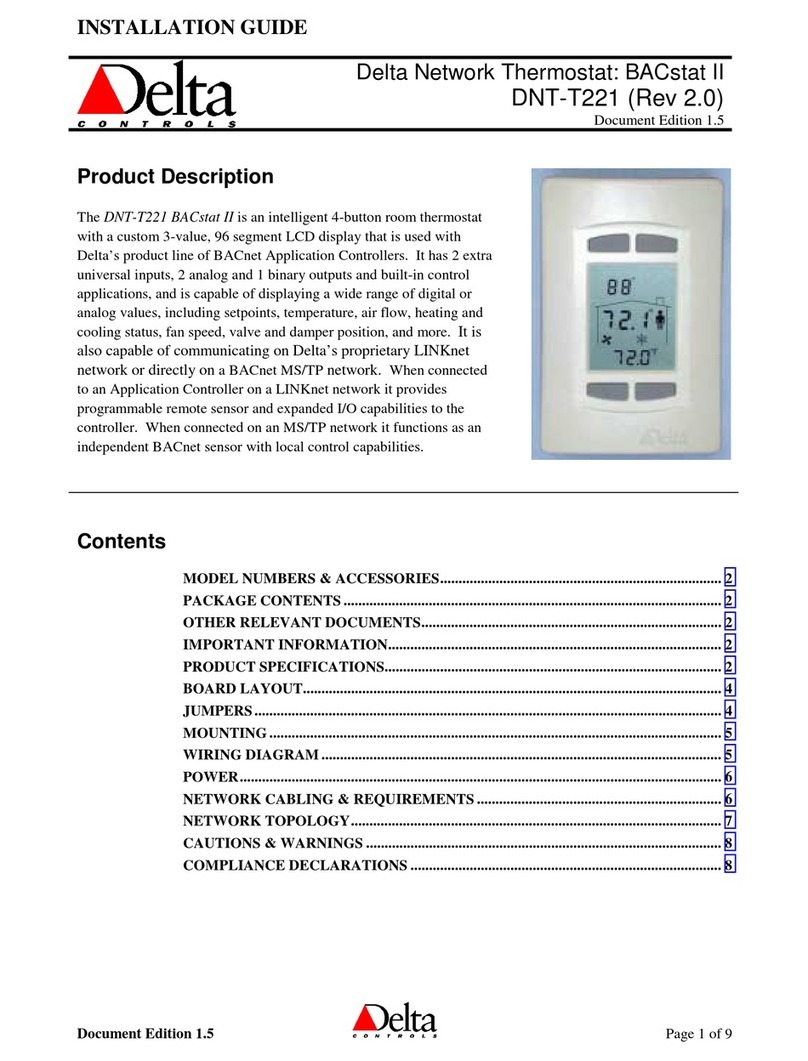
Delta Controls BACstat II User manual

Delta Controls
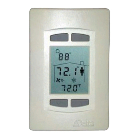
Delta Controls DNT-T103 User manual
Delta Controls
Delta Controls DNT-T221 User manual
Delta Controls
Delta Controls BACstat III DNT-T221-FCU User guide
Delta Controls
Delta Controls BACstat II Series User guide
Delta Controls
Delta Controls HTP User manual
Popular Thermostat manuals by other brands

Honeywell
Honeywell RTH2310 operating manual
bluefin
bluefin WIFI Master Plus THBF855 installation manual
Neptronic
Neptronic EVCBM14NIT2S Specification and installation instructions
Honeywell Home
Honeywell Home T6 Pro Smart user guide
Veris
Veris HWS Series installation guide
Honeywell
Honeywell The Round CT87N owner's manual
