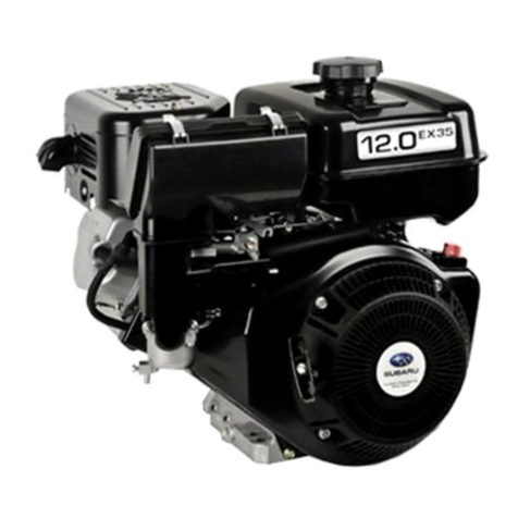
Robin EY14 User manual


ROBIN
AMERICA,
mc.
ROBIN
TO
WISCONSIN
ROBIN
ENGINE
MODEL CROSS
REFERENCE
LIST
ROBIN
WISCONSIN
ROBIN
-
EY08
EYl5
EY
15V
EY20
EY2OV
EY23
EY28
EY35
EY40
EY45V
EY2
1
EY44
EY25
EY27
EY18-3
EHl1
EH12
EH15
EH17
EH21
EH25
EH30
EH3OV
EH34
EH34V
EH43V
EC13V
DY23
DY27
DY30
DY35
DY4
1
W1-080
W1-145
W1-145V
w1-185
W1-185V
Wl-230
W
1-280
W1-340
W1-390
W1-450V
EY21W
EY44W
EY
18-3W
EY25W
EY27W
TWO
CYCLE
WOl-115
WOl-120
WO1-150
WO1-170
wo1-210
WO1-250
WO
1-300
WO
1
-300v
WO
1-340
WO
1 -340V
WO
1 -430V
WT1-125V
WRD
1-230
WRD
1-270
WRD
1-300
WRD1-350
wRDl-410

CONTENTS
Section Title Page
...........................................
1
.
SPECIFICATIONS
1
2
.
PERFORMANCE
...........................................
2
2-1MaximumOutput
........................................
2
2-2Continuous Rated Output
..................................
2
2-3
MaximumTorque andFuel ConsumptionRatio
at
Max
.
Output
.........
2
3
.
FEATURES
................................................
4
4
.
GENERALDESCRIPTION
of
ENGINECONSTRUCTION
...............
4
4-1
Cylinder Crankcase
......................................
4
4-2 Main BearingCover
.......................................
4
4-3Crankshaft
...........................................
4
4-5 Camshaft
.............................................
4
4-7 Cylinder Head
..........................................
5
4-8 Governor
.............................................
5
4-9 Cooling
...............................................
5
4-10
Lubrication
............................................
5
4-11Ignition
..............................................
5
4-13 Air Cleaner
............................................
5
4-14SectionalView
of
Engine
...................................
6
4.4 Connecting RodandPiston
.................................
4
4-6Valve Arrangement
.......................................
5
4-12Carburetor
............................................
5
5.lNSTALLATlON
............................................
14
5-1Installing
..............................................
14
5-2Ventilation
............................................
14
5-3Exhaust Gas Evacuation
....................................
14
5-4
Fuel System
...........................................
14
5-5 PowerTransmission to Driven Machines
.........................
14
5-6
Wiring
.............................................
15
6
.
DISASSEMBLY
and
REASSEMBLY
..............................
21
6-1 PreparationandSuggestions
.................................
21
6-2 Special Tools
...........................................
21
6-3
DisassemblyandRessemblyProcedures
.........................
22
7.MAGNETO
................................................
29
7-1 Magneto
.............................................
29
7-2
Breaker PointAdjustment
..................................
29
74 Magneto TroubleShooting
...................................
31
7-3
Timing
Adjustment
.......................................
30
8
.
GOVERNORADJUSTMENT
...................................
32
9.
CARBURETOR
.............................................
33
9-1
Operation and Construction
.................................
33
9-2
Disassembly
and
Reassembly
................................
34
9-3Adjustment
............................................
36
10
.
RUN-INOPERATION
of
REASSEMBLEDENGINE
...................
37
11
.
TROUBLESHOOTtNG
.......................................
38
11
-1 Starting Difficulties
.......................................
38
11
-2
Engine Misses
...........................................
39
11-3
EngineStops
...........................................
39
114
EngineOverheats
........................................
39
11-5
Engine Knocks
.........................................
40
11-6 Engine BackfiresThroughCarburetor
...........................
40
12
.
CHECKS ANDCORRECTIONS
.................................
41
13
.
CORRECTIONTABLE
.......................................
42
14
.
MAINTENANCE
and
STORING
.................................
48
14-1Daily Checksand maintenance(Every
8
Hours)
....................
48
14-2
Every
20
Hours
ChecksandMaintenance
........................
48
14-3 Every
50
Hours
(10
Day)
ChecksandMaintenance
..................
48
14-4
Every
100
.
200Hours (Monthly)Checks
and
Maintenance
............
48
14-5 Every 500
.
600Hours(Semianual) Checksand Maintenance
...........
49
14-6 Every 1000 Hours (Yearly) Checks
and
Maintenance
.................
49
14-7
PreparationforLong-Term Storage
............................
49

1.
SPEC1
FICATIONS
[
N
m
p
52
0
n
0"
V
t
1
c
t
I
I
i
-1
-

2.
PERFORMANCE
2-1
MAXIMUM OUTPUT
n
TheMaximumoutput of an engine is
such
standard power
as
developed
by
that engine,
after
its
initialrun-inperiodwith
all
the
movingpartsproperlyworn-in,whenoperatingwiththefully
openthrottlevalve.Therefore,it
follows
that
a
newenginemaynotdevelopthismaximum
output in
the
beginning, because moving parts are not in
a
properly worn-in condition.
2-2
CONTINUOUSRATEDOUTPUT
Thecontinuous
rated
outputofanengine
is
such
powerasdeveloped
by
that
enginewhen
running
at
anoptimumspeedmostfavorablefromthepointofviewofenginelifeandfuel
consumptionratio.Therefore,itfollowsthatwhendesigning
a
drivingsystemforany
mechanism,with
a
modelEY14,EY18-3,EY23, EY25-2 and EY27-2 engine,
as
a
prime
mover,
the
continuouspowerrequirementof
that
mechanismmust
be
keptbelow
the
continuous
rated
output specified.
2-3
MAXIMUM TORQUE
and
FUELCONSUMPTIONRATIO
AT
MAX.OUTPUT
The maximum torque of an engine is
that
driving torque of the driving shaft
at
which the engine
is
drivinganexternalload,
while
the
engine
is
developing
its
max.output.Thefuel
consumptionratio
at
max.output
is
that
fuelconsumptionratio
of
anenginewhile
that
engine
is
running
at
the
rnax. output.
PERFORMANCECURVE PERFORMANCECURVE
MODELEY18-38
-2-

PERFORMANCE
CURVE
MODEL
EY23
7
( )
for
B
type
1.5(3.0)
1.0
(2.0)
6
I
5
kg-m
HP
I4
3
I
g1HP.h
3
50
2
300
250
2000
3000
4000
(1
000)
(1
500)
(2000)
rpm
__c
PERFORMANCECURVE
MODELEY25-2
(
)
for
B
type
.h
PERFORMANCECURVE
MODELEY27-2
(
)
for
8
type
1.4(2.8)
1.3(2.6)
7
I
kg-m
6
5
HP
I4
3
I
g1HP.h
340
2
320
2500
3000
3500
4000
(1250)
(1500)
(1750)
(2000)
rpm
-
-3
-

FEATURES
A
compact,lightweightanddurable4-cycleair-cooledenginewithhighpoweroutput,
embodyingingeniousdesigntechniqueandadvancedproductionskill.
n
Simple construction, smart appearance, easy
start.
Reliablepowerforwide.varietyofpurposes,withsmoothspeedcontrollby
a
governor,
under varying
load
conditions.
Economical advantage throughlow fuel consumption.
Great versatility in installation through
a
360°
belt
extension possibility and
a
two side
oil
fill and drain arrangement.
GENERALDESCRIPTJON
of
ENGINECONSTRUCTION
CYLINDER,CRANKCASE
The
cylinderand
the
crankcase
are
die-cast
as
a
compactaluminium mono-block piece.
The
cylinderlinerand
the
valve
seats
are
madeofspecialalloy
cast
ironand
are
imbeddedin
the
aluminiumcasting
as
inserts.Theintakeandexhaustports
are
located
at
oneside
of
the
cylinder and
are
also
made
of
inserted pieces in
the
casting.
Thecrankcase
is
separable
at
thedriving
shaft
sideandthisseparablepiececonstitutes
the
main bearing cover.
4-2
MAINBEARING COVER
As
thealuminiumdie-castmainbearingcover
is
builtontothecrankcaseonthedrivingshaft
side,theengine'inside
are
reached
forinspection,easilybysimplyremovingit.It
is
also
providedwith
a
flangeand
boss
fordirectlymountingoperatingmachinessuch
as
generators
and pumps.
There
are
two
oil filters serving also
as
oil gauges provided
at
two locations.
(However, in
EY18-3
or
EY23
engine,
at
one location in
the
carburetor
side.)
4-3
CRANKSHAFT
Thecrankshaftismachinedfrom
a
carbon
steel
forgingwith
an
inductionhardenedcrank pin.
On
the
fanside,
the
breaker
camisprovidedandon
the
drivingside,
the
crankshaft
gear
is
force-fit.
44
CONNECTINGROD
and
PISTON
The connecting rod
is
machined from an aluminium alloy forging in which the
forged
alloy itself
serves
as
the
bearingmetal
at
both
ends.On
the
largeend,anoilscraper
for
splashing
the
lubricating
oil
is
provided.
Thepistonismachinedfromanaluminiumalloycastingand
is
providedwithtwogrooves
for
compression rings and one groove
for
the
oil ring.
4-5
CAMSHAFT
Thecamshaftismachinedfrom
a
carbon
steel
forgingwithintegralintakeandexhaustcams
and
is
providedwith
a
force-fitcamgear.
In
the
model
B
engine,
the
camshaft
serves
also
as
the
drivingshaft,beingdriven
at
half
the
crankshaftspeed.
In
the
EY14D,EY23D,EY25-2D
and
EY27-2D
engines,
the
camshaft ismachinedfrom
a
specialalloy
cast
ironwithanintegral
camshaft
gear,
andissupported by aluminiumbearingmetalsmachinedintegralwith
the
crankcase
at
both ends. (no
ball
bearing is used)
n
-4
-

4-6
VALVEARRANGEMENT
The exhaust valve ispositioned
in
the
upstream side of the cooling air with the result that the
exhaust valve
is
intensively cooled for engine life improvement.
-
4-7
CYLINDER
HEAD
A
Ricardo type combustion chamber
of
ample area is employed for good combustion efficiency.
The spark plug
is
mounted obliquely to facilitatefuel tank mounting.
4-8
GOVERNOR
The flyweight type governor effectivelyoperatesto maintain
the
selected speed at varying
load.
The model
EY14,EY18-3
and
EY23
engine
is
equippedwith a separate gearing for the governor
to
secure better performance.
4-9
COOLING
Coolingis accomplished
by
a
flow
of air circulated past the cylinder walls and head
fins
from a
combination fan-flywheel.The air
is
guided
by
a cylinder buffle
and
a head cover. The
EY14,
EY18-3,
EY23,
EY25-2
and
EY27-2
engines are equipped with curved vane fans made
in
two
modifications, each
for
direct drive and reduction drive engines.
4-10
LUBRICATION
Lubrication for rotating and sliding parts is accomplished
by
scoopingandsplashing the
oil
in
the crankcase
with
oil scraper attached toconnecting rod.
4-11IGNITION
The ignition system
is
of the flywheel magneto type
with
the ignition timing set
230
before
T.D.C.The magneto comprises a flywheel, ignition coil and abreaker, of which the flywheel
(serving also asafan)
is
mounted on thecrankshaft and the two other members are mounted
directly
in
thecrankcase.(fordetails, refer
to
7.
MAGNETO
section)
The model
EY23
engine normally incorporates an electronic ignition system.
4-12CARBURETOR
A
horizontal draftcarburetor
is
employed. Itssetting has been carefullydetermined after
through testingto achieve best starting,accelerating,fuel consumption, output and other
performances.
For
other detailssuch as construction, refer to
9.
CARBURETOR
section.
4-13
AIR
CLEANER
Themodel
EY
14,
EY18-3
and
EY23
engines are equipped with an oval air cleaner incorporating
8
sponge element.
The cycl.one type air cleaner with a semi-wet double element is optional.
The
model
EY25-2,
EY27-2
engines are equipped
with
an
cyclone type semi-wet double element
air cleaner.
-5-

4-14
SECTIONAL
VIEW
of
ENGINE
4-14-1
MODEL
EY14
FI
Blower
ywheel
(Cooling
Housing
Starting
Pulley-
MODEL
EY14
ver
-6-

Fuel
Tank
MODEL
EY14
-7
-

4-14-2
MODEL
EY18-3
Cover
MODEL
EY18-3
-a-

/-
Tank
/
MODEL EY18-3
-9-

4-14-3
MODEL
EY23
Flywheel
Star
MODEL
EY23
7g
Cover
-
10
-

/"
Tank
Con
Cam
Shaft
MODEL
EY23
-
11
-

4-14-4
MODEL
EY25-2
and
EY27-2
MODEL
EY25-2
and
EY27-2
Cover
-
12
-

I
ti
I
I
\Cam
Shaft
MODEL
EY25-2
and
EY27-2
-
13
-

5.
INSTALLATION
Thelife,
ease
of
maintenance,frequencyof
check
andrepair,andoperating
cost
are
greatly
affected by
the
way
the
engine is installed. When installing the engine, therefore, the following
contents must
be
studied carefully.
n
5-1
INSTALLING
When
installingtheengine,
its
position,couplingconditionswiththeoperatingmachineand
anchoring
or
supporting method must
be
carefully studied.
Especially,whendecidingtheinstallingposition,considerationmust
be
given
to
facilitate
its
routinessuch
as
filingandchecking
of
gasoline
and
oil,
checkingofsparkplugandbreaker,
maintenance of
air
cleaner and oil draining.
5-2
VENTILATION
The
engine must
be
supplied with fresh air
for
cooling and fuel combustion. When
the
engine
is
to
be
operated in
a
cover
or
in
a
small room,
a
propermeansmust
be
providedforcooling
air
re-circulation
or
ducts and baffle plates
for
guiding
a
cooling
air,
because if the temperaturein
theenginecompartment
is
allowed
to
rise,vaporlock,oildeterioration,increaseof
oil
consumption,powerreduction,seizure,
loss
of
enginelife
or
othertroubles
are
caused,and
proper
operation
is
harmed.Thetemperature
of
theenginecompartmentmust
be
maintained
below
50OC
even in summer with necessary ventilation arrangement.
5-3
EXHAUST GAS EVACUATION
Since
the
exhaust
gas
from
the
engine is toxic, when
the
engine
is
operated indoors,
the
exhaust
gas
must
be
evacuated
to
outside.Sincetheoutputpower
of
anengine
is
considerably
influenced
by
the
length
of
the
exhaustduct,itsdiametermust
be
increasedinproportion
to
its
F-,
length.
5-4
FUEL SYSTEM
When
the
standard fuel tank is installed separate from
the
engine, it must
be
so
located
that
its
bottom surface lies within
the
height
of
5
CL
50
cm from
the
fuel joint of the carburetor.
When
the
fueltankisinstalledtoolow,fuelisnotfedproperlyand if itispositioned
too
high,
the
carburetor overflow
is
caused.
When connecting
the
fuelpipe,
to
eliminateairlockandvapor
lock,
the
pipingmust
be
carefullyexaminedforheatconductivity,diameter,bending,and
leakage
throughfittings.The
standard I.D. of the fuel pipe is
4
‘L
5
mm.
5-5
POWER
TRANSMISSION
to
DRIVEN
MACHINES
5-5-1
BELT
DRIVE
Take
the
following notes into condition:-
o
V-belts
are preferred to
flat
belts.
o
The
driving shaft
of
the
engine and
the
driven
shaft
of
the
driven machine must
be
parallel.
o
The
drivingpulleyof
the
engineand
the
drivenpulley of
the
drivenmachinemustbealigned
o
The driving pulley must
be
mounted
as
near
the
engine
as
possible.
o
As
far
as
possible,
the
belt
is spanned horizontally.
o
When starting
the
engine,
the
load must
be
disconnected from
the
engine.
o
If
a
clutch is
not
available,
a
tension pulley
or
other
means must
be
employed.
correctly.
-
14
-

5-5-2
FLEXIBLECOUPLING
When
a
flexible coupling
is
used,
the
runout and mis-alignment between
the
driven
shaft
and
the
engine driving shaft must
be
made
as
small
as
possible.
The
tolerances on
the
runout and mis-alignment
are
specified by
each
coupling maker.
5-6
WIRING
5-6-1
START
by
RECOIL
STARTER,
or
byROPE
The
wiring
is
indicatedin
the
wiringdiagramgivenbelow.Normally,
the
portionsindicatedby
dotted
line
are
not wired in
the
engine
at
the
factory.
1)
Pointsystem
MODEL
EY14
MODEL
EY18-3
~
Stoo Button
Lighting
Switch
Lamp
(6V-8V
\
'Ignition Coil
Lighting
Coil
(Optional Equipment, available
SparkPlug
Contact Breaker
la"
"-7
',15W)
if
required)
'
Lighting
Coil
(Optional Equipment,available if
MODELEY25-2,EY27-2
,Condenser
required)
ir
.ed
)
Fig.
5-6-
7
-
15
-

2)
Electronic ignition system
MODEL
EY14:
CDI (Capacitor Discharge Ignition)
system
Stop
Button BlackMlhite
Pulser
Coil
""".J
Optional
Lamp
Coil
Fig.
58-2
MODEL
EY23
STD:
TIC
(Transistor Ignition Circuit) system
IgnitionCoilConnector
i
Spark
Plug
"
Stop
Button
L
m7
Fig.
5-6-3
-
16
-
This manual suits for next models
4
Table of contents
Other Robin Engine manuals

Robin
Robin EH36 User manual

Robin
Robin DY23-2D User manual

Robin
Robin EH025 User manual

Robin
Robin EH63D User manual

Robin
Robin EX13D User manual

Robin
Robin EH12-2D User manual

Robin
Robin EC05-2 User manual

Robin
Robin EH11/W01-115 Operating instructions

Robin
Robin EC1O User manual

Robin
Robin EY08D User manual
Popular Engine manuals by other brands

Leroy-Somer
Leroy-Somer LSA 47.2 Installation and Maintenance

RHINO MOTION CONTROLS
RHINO MOTION CONTROLS RMCS-2302 Installation Manual and Datasheet

Moons'
Moons' TXM34Q Quick setup guide

Kohler
Kohler LOMBARDINI 9 LD 561-2 Use & maintenance

Teknic
Teknic ClearPath-SCSK Series user manual

FeiaoModel
FeiaoModel DLA Series user manual