EN
89
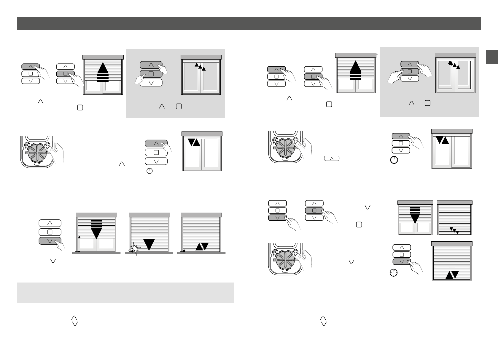
Contents 1/ Use
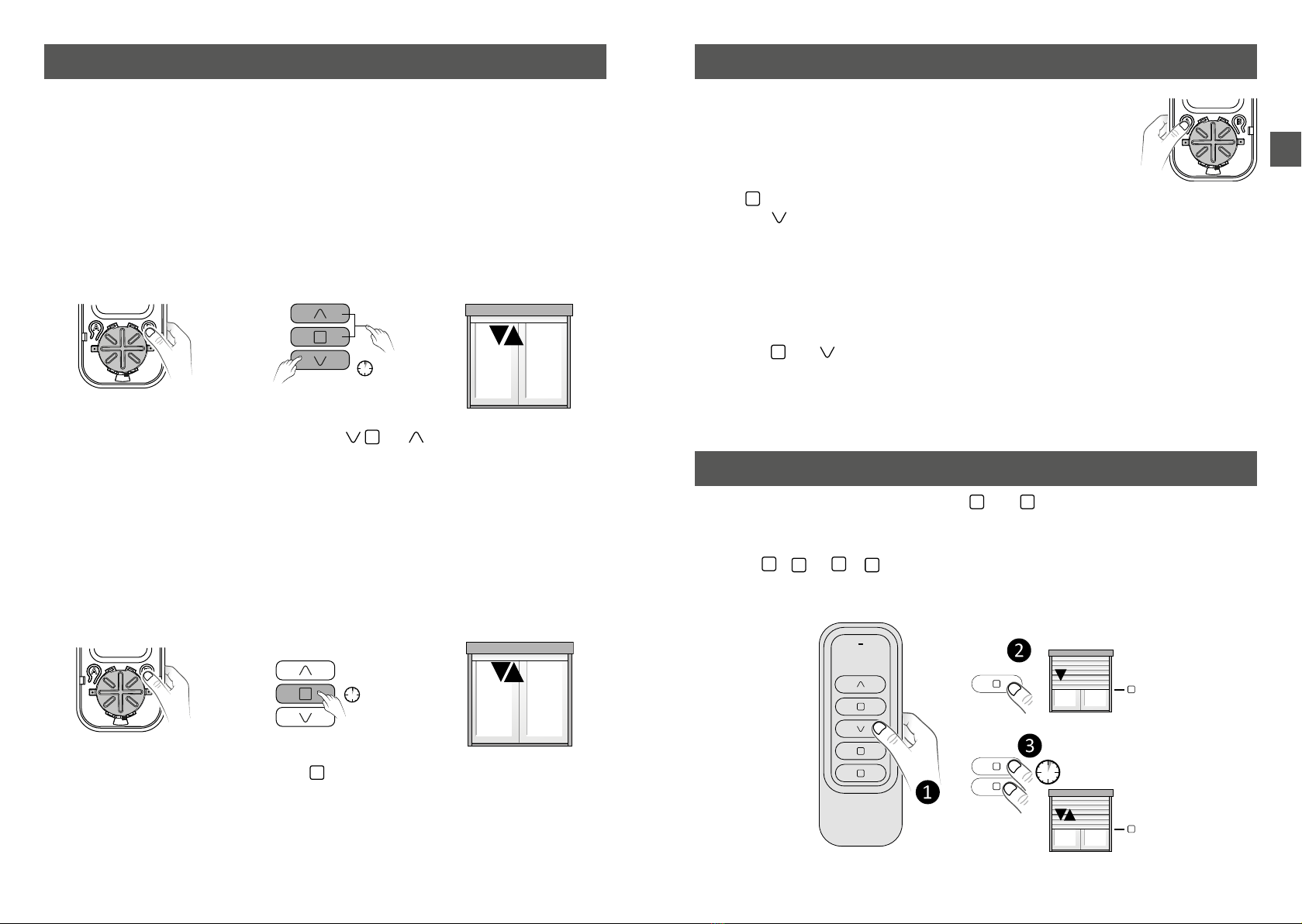
• Press
to raise, and
to lower.
• Press
to stop the shutters.
• Press
to go to favourite position 1 (if it has
been saved).
• Press
to go to favourite position 2 (if it has
been saved).
The LED changes from red to green if the receiver has correctly received the
information.
Control in Silence mode (Tymoov RP2 motors):
In order to reduce the noise level, you can control the motor in Silence mode by
performing a long press on or (2 seconds).
1
2
1/ Use ............................................................................................................................................. 9
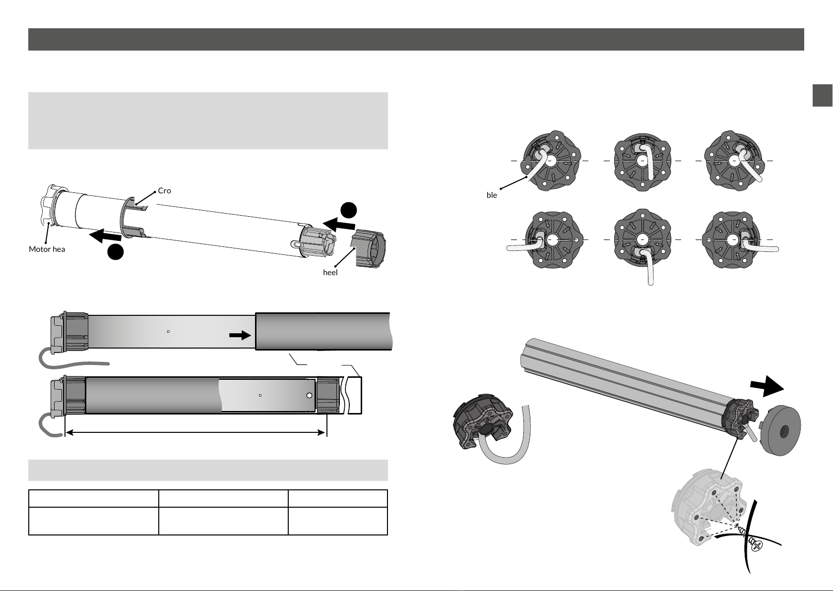
2/ Installation............................................................................................................................10
2.1 Installing the tube.................................................................................................................................. 10
............................................................................................................................................. 12
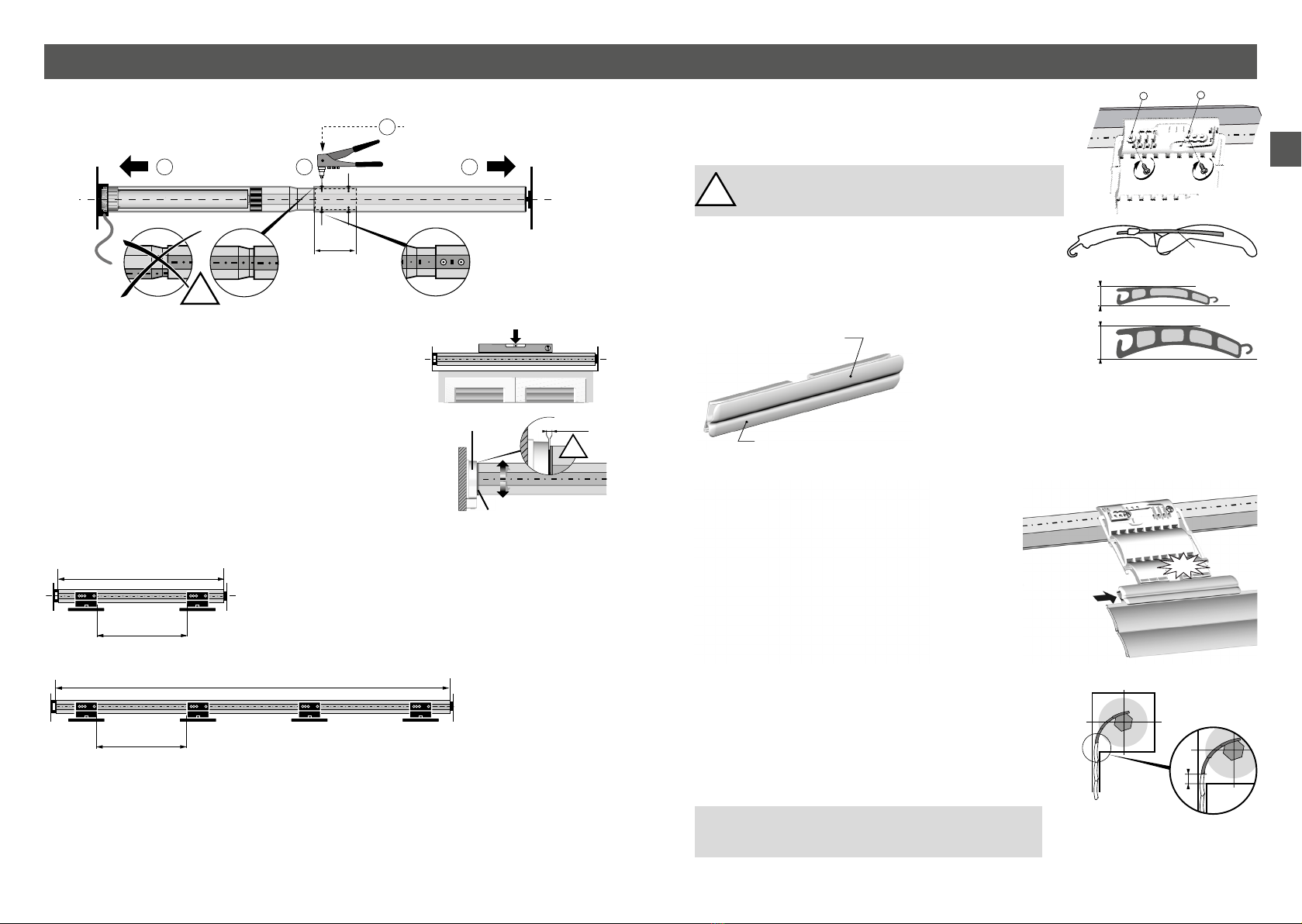
2.3 Installing the fasteners........................................................................................................................ 14
3/ Connection ...........................................................................................................................16
3.1 Wiring without push button ............................................................................................................. 16
3.2 Wiring with a push button................................................................................................................. 16
4/ Starting up for the rst time ..........................................................................................17
...................................................................... 17
4.2 Setting stops............................................................................................................................................. 18
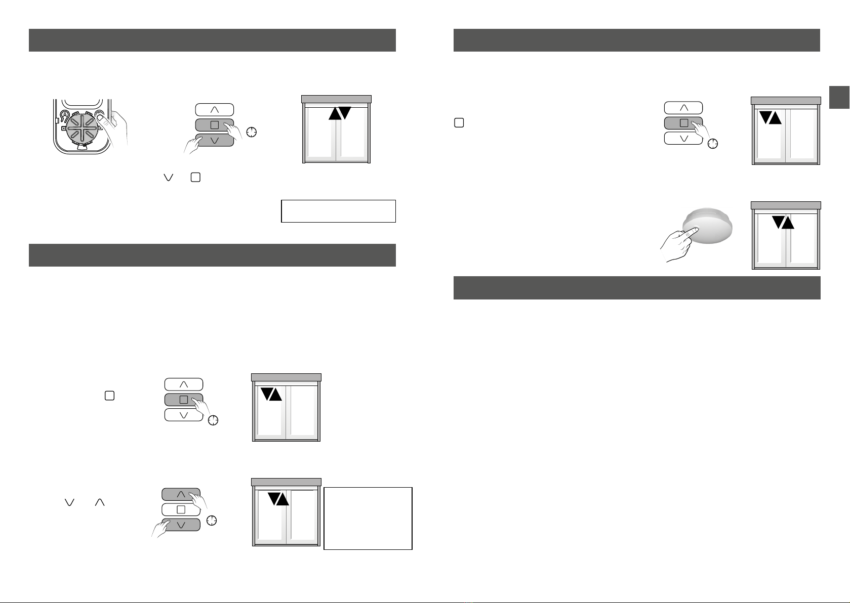
5/ Modifying stops .................................................................................................................22
6/ Associating another transmitter..................................................................................22
7/ Associating a smoke detector .......................................................................................23
8/ Grouped command............................................................................................................23
9/ Obstacle detection ............................................................................................................24
9.1 Setting of the obstacle detection type......................................................................................... 24
for Basic detection (only) ................................................................................................................... 24
10/ Remove one or several associations........................................................................25
.................................................... 25
...................................................................................................................... 25
11/ Favourite positions.........................................................................................................25
12/ Association with an alarm control unit...................................................................26
...................................................................................................................... 26
......................................................................................... 27
13/ Location/Mounting.........................................................................................................28
14/ Battery replacing.............................................................................................................28
15/ Operation with a push button ...................................................................................28
16/ Setting stops from the push button (local control) ............................................29
........................................................................................................... 29
..................................................... 30
..................................................... 31
................................................................................................................. 32
....................................................................................................................................... 33
17/ Your remote control is lost or not functioning.....................................................34
18/ Factory reset ....................................................................................................................34
19/ Troubleshooting...............................................................................................................35