DELTA DORE TYMOOV radio RP2 Series User manual

EN Wireless Tubular Motor range
TYMOOV radio
xRP2 / DxRP2 / xRE2

EN
2 3
Recommendations
WARNING: Important security instructions
Incorrect installation may cause severe injury
Follow all the instructions and keep this installation guide in a safe
place.
-TYMOOV xRP2/DxRP2 or xRE2 motors are designed solely for the
operation of roller shutters for home use. For any other use, please
contact our technical department.
- The minimum inner diameter of the roller tube is 47 mm, but the
tube must be chosen according to the weight and length of the
apron. Consult the tube manufacturers’ charts.
- Do not operate the roller shutter if people or objects are in the
movement area.
- The moving parts of the motor, installed at a height of less than 2.5m,
must be protected.
- Before installing the motor, remove all superuous cords and take
out of service any equipment not required for the motor to operate.
- IMPORTANT: Do not operate the shutters or cut off their power
supply when maintenance or cleaning work is being carried out on
the equipment or in close proximity (e.g. window cleaning).
- Monitor the shutter when it is moving and stand clear until it is
completely closed.
-
Do not allow children to play with the xed control devices. Keep
remote control devices out of the reach of children.
- This device may be used by children aged 8 years or older and
by persons with reduced mobility or reduced sensory or mental
capacities, or persons lacking in experience or knowledge, provided
that they are properly supervised or have been given instructions on
how to use the device safely and that the risks involved have been
understood.Children must not play with the device. Cleaning and
maintenance by the user must not be carried out by unsupervised
children.
- The operating device of an unlockable switch must be in direct view
of the driven part, but kept away from the moving parts. It must be
installed at a height of at least 1.5m.
- The xed control devices must be installed in a visible area.
- When using an unlockable switch, ensure that all other
persons in the room stand clear of it;
- Frequently check the equipment to detect any imbalances or signs of
wear or damage to cables and springs.
- Do not use the device when repairs or adjustments are required.
Preliminary elements
- TYMOOV xRP2/DxRP2 or xRE2 motors are motors tted with 868
MHz - X3D wireless receivers. They are compatible with the range of
DELTA DORE X3D control systems and alarms.
- Sufciently rigid roller shutter blades should be used.
- When the roller shutter is closed, the apron must not overlap the
runners by more than one 1/2 blade (max.).
- The apron fastenings or automatic fasteners used on the shutter
must comply with the recommendations for use provided by the
manufacturer
The maximum locked rotor torques for TYMOOV xRP2/DxRP2 or
xRE2 motors are: 6 Nm : 10Nm / 10 Nm: 15Nm / 20 Nm: 27 Nm.
Models which cannot support these torques cannot be mounted. The
number of fasteners must be adjusted according to the model and
number of links.
- If used with upper stops, preferably use systems built into the
runners.
- Pay attention to the frame rigidity with stop systems on the shutter
blades.
- TYMOOV xRP2/DxRP2 or xRE2 motors check the
physical stops every 100 operations, so the motor automatically
compensates for any apron movement.

EN
4 5
Recommendations
- Correct operation of the motor is ensured if it is installed and used
according to the following recommendations.
The peripheral elements such as the roller tube, supports, fastenings,
etc. must be chosen correctly and assembled in compliance with
good practice. Furthermore, the motor operating environment and
power required are elements that must be carefully chosen and
assessed. The characteristics of the driven part must be compatible
with the rated load and operating time.
- A-weighted sound pressure level: LpA ≤ 70 dB(A).
- Cables going through a metal wall must be protected and isolated by
a sleeve.
The TYMOOV xRP2/DxRP2 or xRE2 cable can be disassembled.
- If the power cable is damaged, it must be replaced by the
manufacturer, after-sales service or similarly qualied personnel in
order to prevent hazards.
- The motor must be chosen according to the requirements of the load
bearing support. See our charts for selecting the motor according to
the shutter type. A plate on the motor indicates the nominal torque
and operating time.
- TYMOOV xRP2/DxRP2 or xRE2 tubular motors are designed to
operate intermittently (4 minutes of continuous operation). They
are electronically protected to prevent overheating. If there is a
thermal shutdown, the motor will operate again after a time period
of approximately 30 seconds. To operate again for 4 minutes, the
motor must have returned to room temperature.
- If an attempt is made to raise the shutter (for example: intruder test),
the motor will lower the apron. Caution, your ngers may be caught.
DELTA DORE hereby declares that the motorised systems covered by these
instructions comply with the essential requirements set out by the Machinery
Directive 2006/42/EC and the European directive RED 2014/53/EU.
The EU declaration for this equipment is available on request
from:
Service “Info techniques”
DELTA DORE – 35270 Bonnemain (France)
email: [email protected]
DELTA DORE
35270 - BONNEMAIN - France
Because of changes in standards and equipment, the characteristics given in the text and the illustrations in this
document are not binding unless conrmed by our departments.

EN
67
Contents
• Power supply: 230V - 50 Hz +/- 10%
• Class II insulation
• Operating time: 4 minutes
• Electrical power :
TYMOOV 6RP2 / 6RE2 : 40 W
TYMOOV 10RP2 / 10RE2 / D10RP2 : 50 W
TYMOOV 20RP2 / 10RE2 / D20RP2 : 70 W
• X3D radio frequency: 868.7 MHz to 869.2 MHz
• Maximum wireless power < 10 mW Category 2 receiver
• Radio range: 100-300 metres in an open eld, variable depending on the
associated equipment (the range can vary depending on the installation conditions
and the electromagnetic environment)
• Number of associated transmitters: 16 maximum
• A-weighted sound pressure level: LpA ≤ 70 dB(A).
• Degree of protection: IP 44
• Operating temperature: -20°C -> + 60°C
1/ Technical Characteristics
1/ Technical Characteristics........................................................................7
2/ Motor tting.................................................................................................8
2.1 Crown and wheel assembly .................................................................................8
2.2 Assembly in the tube............................................................................................... 8
2.3 Motor head position................................................................................................ 9
2.4 Attaching the motor to the mount.................................................................... 9
3/ Connection ................................................................................................10
3.1 Wiring without push button, only by transmitter .................................. 10
3.2 Wiring with a push button................................................................................. 10
4/ Starting up for the rst time ...............................................................11
...................................... 11
4.2 Setting stops............................................................................................................. 12
5/ Modifying stops ......................................................................................16
6/ Associating another transmitter.......................................................16
7/ Linking a smoke detector directly to the motor..........................17
8/ Grouped command.................................................................................17
9/ Obstacle detection .................................................................................18
9.1 Setting of the obstacle detection type......................................................... 18
9.2 Adjustment of the sensitivity of obstacle detection
for Basic detection (only) ................................................................................... 19
10/ Remove one or several associations .............................................19
10.1 Remove the remote control association with the motor.................... 19
10.2 Remove all associations...................................................................................... 19
11/ Favourite positions..............................................................................20
12/ Association with an alarm control unit........................................21
12.1 Associating Performance DxRP2 or xRP2 radio motor ...................... 21
................................................ 22
......................................................... 22
13/ Your remote control is lost or not functioning..........................23
13.1 From a new remote control .............................................................................. 23
13.2 From the push button .......................................................................................... 23
14/ Operation with a push button ........................................................23
15/ Setting stops from the push button (local control) .................24
15.1 Recording 2 automatic stops ........................................................................... 24
..................... 25
..................... 26
15.4 Recording 2 manual stops ................................................................................. 27
15.5 Removing stops....................................................................................................... 28
16/ Factory reset .........................................................................................28
17/ Troubleshooting....................................................................................29
EN
89
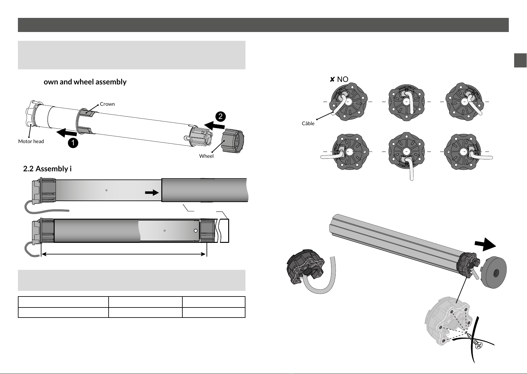
2/ Motor tting
• Never hit the motor head or output shaft to t the motor into the tube.
Never pierce the tube when the motor is installed.
• To attach the apron, use screws that do not enter the tube by more than 1 mm.
2.1 Crown and wheel assembly
2.2 Assembly in the tube
For attachment and driving accessories as well as mechanical parts,
consult our catalogue.
Model Length for drilling (L) Total length
TYMOOV 6, 10 and 20 Nm 395 mm 424 mm
Tube
L: length for drilling wheel
attachment by screws or rivet
2.3 Motor head position
The motor head must be positioned on the mount such that the cable outlet is in the
lower part when seen horizontally.
2.4 Attaching the motor to the mount
Push the tube/motor (A) onto the mount (B) until it locks into place (click).
8 NO 8 NO 8 NO
4 OK 4 OK 4 OK
Câble
(A)
(B)
“Click”
1
2
Crown
Motor head
Wheel
“Click”
Ensure that you create a loop in the
power cable to prevent water entering
the motor
It is strictly prohibited to
screw into the motor head.
EN
10 11
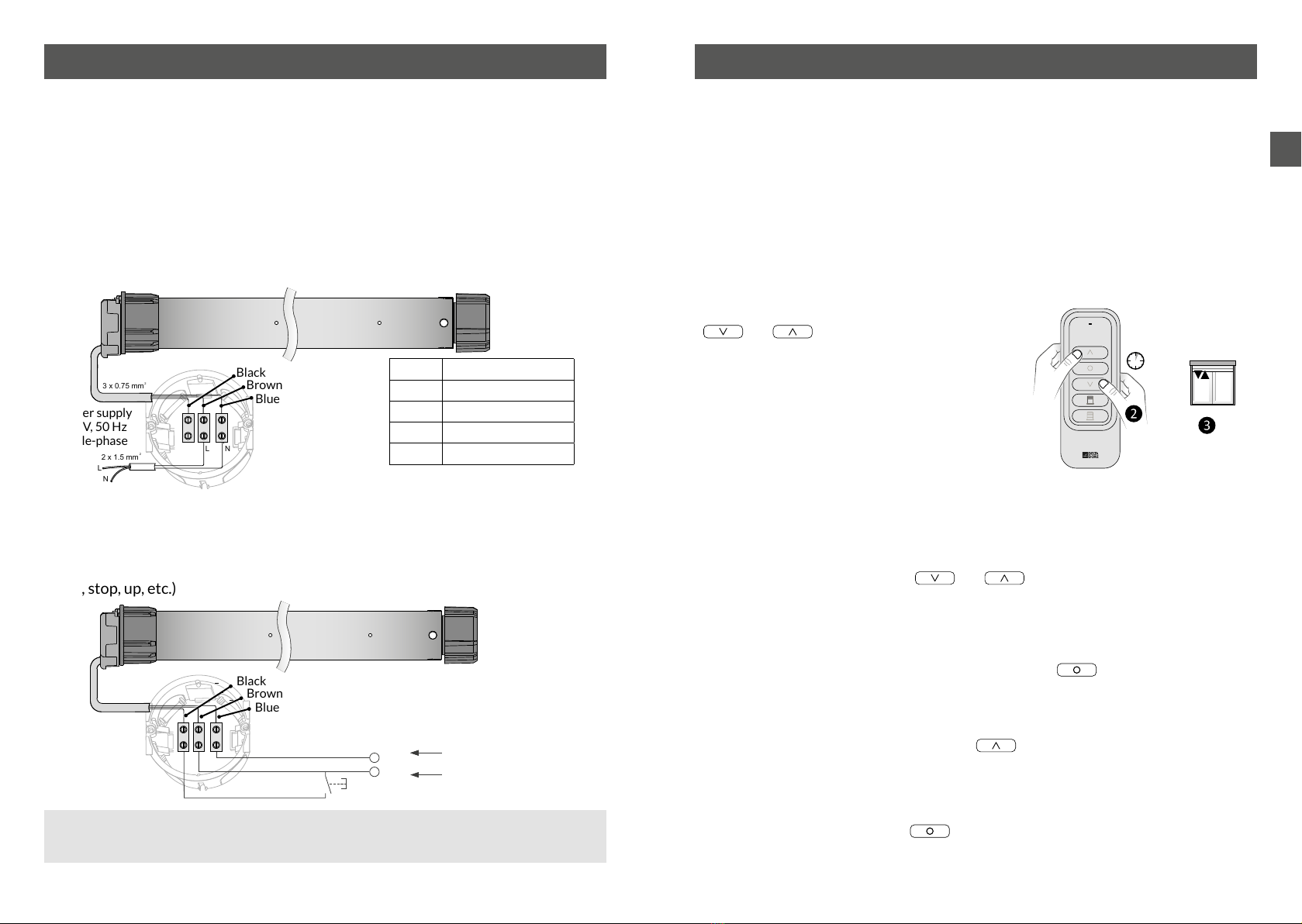
3/ Connection 4/ Starting up for the rst time
The rst time it is switched on, the motor will make a short movement in both
directions to indicate that it has not been associated with a transmitter.
The motors are automatically in association standby mode
You have 5 minutes after start-up to associate the motor to the control device.
4.1 Associating the rst remote control to a motor
4.1.1 Case 1: one motor only is switched on
❶The motor is in association standby mode.
❷On the remote control, press
and at the same time and hold for
3 seconds, until the LED ashes red. Release.
If the motor is found, the LED will light up
green briey.
❸After a few seconds,, the shutter will activate
twice to conrm the association.
The remote control will now be associated
and the motor will switch automatically
to “Set stops” mode.
4.1.2 Case 2: several motors are switched on
❶On the remote control, press and at the same time and hold for 3
seconds, until the LED ashes red. Release.
The remote control will search for the different motors.
The LED will ash red, then green briey when a new motor is detected.
❷When the LED starts ashing red slowly, press the button as many times
as required to select the motor (receiver) to associate.
The corresponding shutter will be activated briey once.
❸Once the motor has been found, press briey.
❸After a few seconds,, the shutter will be activated briey twice to conrm the
association.
To exit association mode, hold for 3 seconds.
You will then be able to pass to “Set stops” mode.
> 3s
The electrical wiring must comply with EN, IEC and national institute standards for
installation (e.g.: NF C15-100 for France).
In all cases, it must still be possible to switch off the power supply by using an
omnipolar device in accordance with the applicable installation requirement. If
the motor is delivered with a H05VVF power cable, this cable cannot be placed
outdoors, unless it is inside a UV-resistant duct.
For an outdoor use, the motor must be equipped with a RNF or RRF rubber cable
with at least 2% carbon. Contact the sales department.
3.1 Wiring without push button, only by transmitter
3.2 Wiring with a push button
The TYMOOV RE2/RP2 motor can be activated in hard-wired mode.
The command is made with a push button. The motor works in sequence (up, stop,
down, stop, up, etc.)
N
L
N
L
2 x 1.5 mm 2
3 x 0.75 mm2
Blue Neutral
Brown Phase
Black Not connected
L Phase
N Neutral
Black
Brown
Blue
The black wire must be insulated
(e.g. with a screw joint).
Power supply
230 V, 50 Hz
Single-phase
230 V.a.c. / 50 Hz
N
L
Black
Brown
Blue
When the stops are not programmed on the motor, press and hold the push
button for more than 1 second.
EN
12 13
4/ Starting up for the rst time
STOP
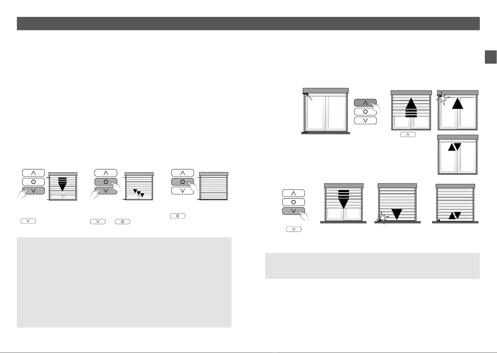
4.2 Setting stops
You can use Auto mode if there are both upper and lower physical stops. The motor
will automatically detect its end of travel distances.
If there are no upper physical stops and/or automatic locks, you must set the end of
travel manually.
Thanks to the step-by-step mode, you can stop the shutter in the exact position you
choose.
There are several ways to congure stops:
• 2 automatic stops,
• 1 manual stop and 1 automatic stop,
• 2 automatic stops,
Fast forward
For fast forward,briey
press then release the
button.
Principle
Step-by-step setting
To scroll step by step, briey
press and release the
and buttons at
the same time.
Shutter stop
Briey pressing the
button will stop the
shutter in the chosen position.
4.2.1 Setting 2 automatic stops
x 2
The shutter will not be locked when these stops are subsequently reached.
The motor will reverse its direction slightly so that there is no force on the
shutter.
x 1
Upper physical
stop
Lower physical
stop
Stop on shutter
blade
Press the button
briey until the shutter
reaches the upper stop.
The stop position will now be automatically set.
The motor will be activated briey.
The stop position
will now be
automatically set.
The motor will
be activated
twice
❶ Automatic upper stop
❷ Automatic lower stop
❸ The stops are set
There is no priority direction for the stop teaching process.
The rst stop can be the upper stop or the lower stop.
Do not use the stepwise mode to congure the automatic stops (only for manual
stops).
It is possible that the shutter will move in the opposite direction to the button
you press.
The motor will detect the rotation direction itself if the shutter is in a vertical
position.
You can reverse too the direction manually by briey pressing button B under the
front panel of the remote control so that the green LED ashes.
Then press the up/down buttons at the same time and hold for 3 seconds.
The mode will be automatically exited.
Press the button briey until the shutter
reaches the lower stop.

EN
14 15
The shutter will not be locked when these stops are subsequently reached.
The motor will reverse its direction slightly so that there is no force on the shutter.
4/ Starting up for the rst time
> 3s
x 2
x 1
4.2.2 Setting 1 manual stop + 1 automatic stop
❶Position the shutter
❸ Automatic stops
❹ The stops are set
Scroll step by step
❷ Setting the position of the manual stop
Press button B on the front panel
of the remote control, until the LED
ashes green.
Then, press and hold the
button for ~3 seconds
until the motor is activated
briey
The motor
will be activated
briey
The motor
will be activated
twice
Press the button until
the shutter reaches the lower stop.
The stop position
will now automatically
be set.
> 3s
> 3s
x 1
x 2
4.2.3 Setting 2 manual stops
❶Position the shutter
❷Setting the position of the first stop (e.g. Upper manual stop)
❸Setting the position of the second stop (e.g. lower manual stop)
❹ The stops are now set. Exit the settings mode.
Press the button until the shutter is
in the required position, then press to
stop it (*).
Press the button until the shutter is
in the required position, then press to
stop it (*).
To scroll step by step, briey press then
release the and buttons at
the same time.
To scroll step by step, briey press then
release the and buttons
at the same time.
Press button B on the front panel
of the remote control,until the LED
ashes green.
Then, press and hold
the button for ~3
seconds until the motor is
activated briey. The upper
manual stop will now be set. The motor
will be activated briey.
Press the button
to move the shutter to the
required position, then
press to stop it.
Press button B on the front panel
of the remote control, until the LED
ashes green.
Then press the button
for ~ 3 seconds until the motor is
activated briey.
The lower manual stop will now
be set.
When the setting of
the2nd stop is completed,
the motor will validate by
activating itself twice.
Scroll step by step
(*) The shutter may move in the opposite direction to the pressed-on button.
This will automatically be corrected after the 2 stops are recorded, which will be done systematically:
- by pressing for 3 seconds on , for the upper stop,
- by pressing for 3 seconds on , for the lower stop,
even if the buttons are reversed.

EN
16 17
> 3s
> 3s
x 2
x 1
The motor has already been associated with a transmitter.
You can associate various transmitters from the X3D range (telephone transmitter,
other remote control, etc.) with the up/down function of the motor. Number of
transmitters that may be associated: 16 max.
To associate these transmitters, please consult their instructions.
An additional user guide describing the operation of the TYMOOV motor with the
TYXIA 1712 and TYXIA 2330 remote controls is available on the website
www.deltadore.com.
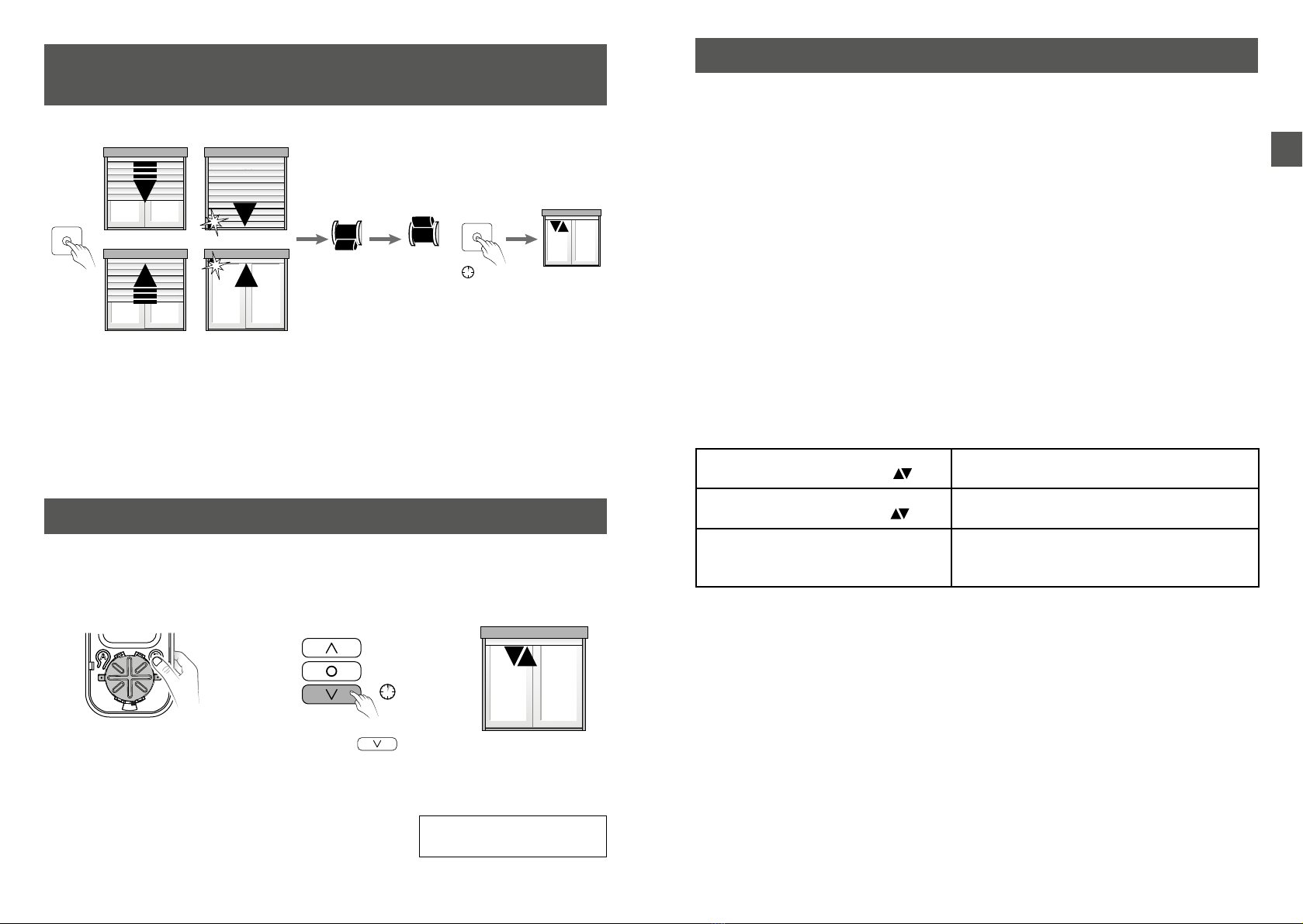
The stops must rst be removed then set again for them to be modied.
Remove them by proceeding as follows:
See section 4.2 “setting stops” to set them again.
5/ Modifying stops
6/ Associating another transmitter
> 3s
x 2
The motor
will be activated briey.
twice.
Press button B on the front
panel of the remote control,
until the LED ashes green.
On the transmitter, press and hold
the et buttons at
the same time for more than 3
seconds until the LED comes on.
The stops will now be
removed
The new
remote control
will now be
associated with the
motor
On the transmitter that is already
associated, press the
button for more than 3 seconds
until the motor is activated briey.
Validate on the transmitter to be
associated (e.g. new remote control)
On the new remote control,
press the and
buttons at the same time for
more than 3 seconds until the
LED comes on.
The motor will briey
be activated twice.
You want to control the opening of roller shutters in the event that smoke is
detected.
Motor type Linking to a wireless smoke detector
TYMOOV xRP2 and DxRP2 Wireless smoke detector directly linked to the motor
TYMOOV xRE2
(Version > S02.04.00) Wireless smoke detector directly linked to the motor
TYMOOV xRE2
(Version < S02.04.00)
Only by linking your motor and the wireless smoke detector to a
TYXAL+ alarm system
To nd out the type and version of the motor, consult the «Troubleshooting»
chapter.
7/ Linking a smoke detector directly to the
motor
> 3s
x 2
x 1
When the motors have been associated via a bidirectional grouped command, they
will start up at slightly staggered time intervals (100 ms) in order to limit the peak
current in the electric line during start-up.
• If the motors were associated at the same time in a grouped command, they will
start up in the order in which they were detected during the association process.
E.g. It could be that one lounge motor starts rst, followed by a bedroom motor,
then the second lounge motor. There may be a time lapse between the rst and
second lounge motors starting.
• If you would like the motors to start in a specic order, you should associate them
one by one in the order you require.
Refer to the user guide for each remote control.
E.g. If you have 3 roller shutter motors in one lounge, associate them one by one
with the remote control so that they start up without a big time lapse.
8/ Grouped command
On the transmitter that is already
associated, press the button for
more than 3 seconds until the motor is
activated briey.
Briey press the button of the detector.
The motor will briey be activated
twice.

EN
18 19
10/ Remove one or several associations
10.1 Remove the remote control association with
the motor
- Remove the front panel of the remote control.
- Press button A.
The LED will ash red.
- Press as many times as required to select the motor (receiver) to remove.
- Press the button.
The motor will be activated briey
- Press button A to exit.
10.2 Remove all associations
- Remove the front panel of the remote control.
- Press button A.
The LED will ash red.
- Press the and buttons at the same time and hold for 3 seconds.
The motor will be activated briey
- Press button A to exit.
All the associated motors will be removed.
9/ Obstacle detection
The motors of the TYMOOV range include the obstacle detection feature.
It fully protects the roller shutter mechanism.
After locking on an obstacle, the motor reverses direction by about 15 cm.
Obstacles can only be detected when the stops have been set.
9.1 Setting of the obstacle detection type
For Radio Performance xRP2 and DxRP2 motors, you have a choice between two
detection modes:
- Protect+ Detection: (default mode), more efcient obstacle detection, preventing
the apron from unwinding in the casing.
- Basic Detection: detection of obstacles with unwinding of the apron in the casing.
Repeat the operations above to switch between modes.
The Radio Efcacité xRE2 motor only has Basic obstacle detection.
> 3s x 2
Press button B on the front
panel of the remote control,
until the LED ashes green.
On the transmitter, press together
and hold down the .
and buttons for more than 3
seconds until the LED comes on.
The motor operates briey:
once = Protect+ Detection
(default setting)
twice = Basic Detection
9.2 Adjustment of the sensitivity of obstacle detection
for Basic detection (only)
If an inadvertent obstacle is detected, you can reduce the detector’s sensitivity to
the obstacle.
Repeat the operations above to switch between modes.
> 3s x 2
Press button B on the front
panel of the remote control,
until the LED ashes green.
On the transmitter, press and
hold the button for
more than 3 seconds until the
LED turns on.
The motor will be
activated briey:
Once = high sensitivity
Twice = low sensitivity

EN
20 21
11/ Favourite positions
You can save up to 2 favourite positions: and .
❶❷ Set the shutter to the required position.
❸Press and for 3 seconds to save the position.
The shutter will be activated briey to conrm the association.
Release.
Repeat the operations for the 2nd favourite position.
> 3s
12/ Association with an alarm control unit
Association of the motor with an alarm control unit enables:
- the anti-intruder function (attempt to lift up the shutter), which is only possible
with the Radio Performance DxRP2 and xRP2 motors, non-compatible with the
Efcacité RE2 radio motors.
- the surveillance stop/start report, compatible with all motors.
12.1 Associating Performance DxRP2 or xRP2 radio motor
>5s
Bip
ON OFF >5s
Bip
ON
Bip
> 3s
x 2
Set the alarm control unit to Maintenance mode, then to “Add product” mode.
❶Set the alarm control unit to “Add product” mode.
❷Associate the intruder mode with the alarm control unit
Press button B on the front
panel of the remote control
twice, until the LED ashes
orange.
Then, press and hold the
button for ~3 seconds until the
motor is activated briey.
The alarm control unit will beep. The alarm control unit will beep.
The roller shutter will be briey
activated twice.
For intruder detection to work, the lower stop must be recorded
automatically with locks.
Intruder surveillance is only active if the alarm is activated and the shutter
closed.
❸Exit Add product mode and Maintenance mode
Briey press the OFF button.
The LED changes from red to green to conrm the action.
The alarm control unit’s led ashes a beep.
Press the OFF button once again.
The LED changes from red to green to conrm the action.
The alarm control unit beeps twice and its LED switches off.
OFF OFF
Bip...Bip

EN
22 23
11/ Association with an alarm control unit 13/ Your remote control is lost or not functioning
These procedures are used to set the motor to association wait mode for a new
control unit (Tyxia 1703, 1712, TYDOM, etc.) when the remote control of the
relevant motor has been lost or is out of order.
13.1 From a new remote control
Switch off the motor power supply, wait 10 seconds, then switch the motor back on.
Other motors are connected to the same circuit breaker and are not concerned
by the change of remote control.
After reactivating, operate each of them once (using their master remote control)
before associating the new remote control.
From a new remote control:
- Press the B button on the front panel of the remote control twice, until the LED
ashes orange.
- Press and for 3 seconds until the ashing stops.
The motor (receiver) has not been associated before
- Associate the new remote control to the motor (see § 3.1).
13.2 From the push button
If a push button connects the motor to a local control, you can set the motor to
association wait mode.
To do this:
• Switch off the mains
• Wait for 10 seconds
On the push button:
• Press and hold the button for 3 seconds while switching the mains back on
• Release the push button when the motor gives an acknowledgement conrming
that the motor is in association wait mode (it only remains in association mode for 2
minutes)
12.2 Associating an Efcacité RE2 radio motor
12.3 Dening the motor’s operating mode
... ... ...
>5s Bip
ON OFF
> 3s
x 1 x 2
On the motor remote control,
press the button for more
than 3 seconds until the motor
operates briey.
Set the alarm control unit to Maintenance mode, open it and
then briey press button 2 of the control unit.
The motor briey starts twice.
Close the control unit.
> 3s
Operation of modes 1 and 2:
When surveillance is activated, the shutter will close fully.
❶Press button B on the front panel of
the remote control twice, until the LED
ashes orange.
❷Then, press the button for ~3
seconds until the motor is activated
briey.
The motor is activated once: Mode 1
The motor is activated twice: Mode 2
The motor is activated 3 times: Mode 3
Repeat operations ❶and ❷to change
from one mode to another.
The motor will be
activated
briey.
Alarm
activation Alarm stop
Mode 1 (by default) The shutter closes The shutter remains in
position
Mode 2 The shutter closes The shutter opens
Mode 3 The shutter remains in
position
The shutter remains in
position
When the system is operated with a push button, the motor works in sequence
(press once: up... press a 2nd time: stop... press a 3rd time: down... press a 4th time:
stop... press a 5th time: up...).
Only for xRP motors
Pressing and holding the push button (> 2 seconds) causes the shutter to operate at
slow speed («Silence» mode).
14/ Operation with a push button

EN
24 25
15/ Setting stops from the push button (local control)
15.1 Recording 2 automatic stops
Press and hold the push button (> 2 seconds)
so that the motor operates in the up or down
direction.
When the motor detects the 1st stop (upper or
lower), then the motor operates once.
Press and hold the push button (> 2 seconds) so
that the motor operates in the opposite direction.
When the motor detects the 2nd stop (upper or
lower), then the motor operates once.
> 2s
x 1
OR
> 2s
x 2
OR
15.2 Recording rstly an automatic stop then a manual stop
Press the push button (> 2 seconds) so that the
motor operates in the up or down direction.
When the motor detects the 1st stop (upper or
lower), then the motor operates once.
> 2s
x 1
OR
x 3
+
> 2s
> 2s
x 2
+
> 2s
x 2
STOP
OR
Press the push button (> 2 seconds) so that the
motor operates in the opposite direction.
Briey press the push button to stop the motor at
the position corresponding to the manual stop.
Then,
- if the shutter is down: briey press the push
button 3 times, then press and hold the push
button (> 2 seconds)
- if the shutter is up: briey press the push button
2 times, then press and hold the push button (> 2
seconds)
The motor then operates twice to conrm that the
2nd stop is recorded.

EN
26 27
15/ Setting stops from the push button (local control)
15.3 Recording rstly a manual stop then an automatic stop
Press the push button (> 2 seconds) so that the
motor operates in the opposite direction.
When the motor detects the 2nd stop (upper or
lower), then the motor operates once.
> 2s
x 1
OR
x 3
+
> 2s
> 2s
x 2
+
> 2s
x 2
STOP
OR
Press the push button (> 2 seconds) so that the
motor operates in the up or down direction
Briey press the push button to stop the motor at
the position corresponding to the manual stop.
Then,
- if the shutter is down: briey press the push
button 3 times, then press and hold the push
button (> 2 seconds)
- if the shutter is up: briey press the push button
2 times, then press and hold the push button (> 2
seconds).
The motor then operates twice to conrm that the
1st stop is recorded.
15.4 Recording 2 manual stops
x 3
+
> 2s
> 2s
x 2
+
> 2s
x 2
STOP
OR
Press the push button (> 2 seconds) so that the
motor operates in the up or down direction
Briey press the push button to stop the motor at
the position corresponding to the manual stop.
Then,
- if the shutter is down: briey press the push
button 3 times, then press and hold the push
button (> 2 seconds)
- if the shutter is up: briey press the push button
2 times, then press and hold the push button (> 2
seconds).
The motor then operates twice to conrm that the
1st stop is recorded.
> 2s
x 3
+
> 2s
x 2
+
> 2s
x 2
STOP
OR
Press the push button (> 2 seconds) so that the
motor operates in the opposite direction.
Briey press the push button to stop the motor at
the position corresponding to the manual stop.
Then,
- if the shutter is down: briey press the push
button 3 times, then press and hold the push
button (> 2 seconds)
- if the shutter is up: briey press the push button
2 times, then press and hold the push button (> 2
seconds)
The motor then operates twice to conrm that the
2nd stop is recorded.
EN
28 29
15/ Setting stops from the push button (local
control)
15.5 Removing stops
+
> 3s
< 5s
x 2
OFF
ON
> 2s
OR
• If the motor is not working:
- Check that the wiring corresponds to the diagrams in the “Connection” chapter.
- Check the power supply in the network.
- Check that the motor is not in thermal protection mode; just wait a few minutes for
it to cool down.
- Check whether there is a problem linked to the end of travel settings and
reset them.
• The end of travel points are not applied:
- Check the mechanical components of the system (stabilisation, play, distortion, etc.)
- Check whether there is a fault linked to the end of travel settings and reset them.
• The green LED does not ash after briey pressing button B.
- Several motors are associated with the remote control.
Therefore, you cannot access the setting modes in this case.
The remote control must only be associated with one motor for the settings.
• To nd out the type and version of the motor used.
- Position the shutter in an intermediate position (neither open nor completely
closed).
- Press the STOP button on the remote control 3 times:
The motor operates twice (
x 2
x 1
)TYMOOV xRP2 and DxRP2
(software version S02.04.00 and higher)
The motor operates once (
x 2
x 1 )TYMOOV xRE2
(software version S02.04.00 and higher)
The motor does not respond
TYMOOV xRE2 or xRP2 or DxRP2
(software version < S02.04.00)
See label on the motor
17/ Troubleshooting
Press the push button once to move the shutter
down or up.Switch off the mains within 5 seconds
after the motor reaches the upper or lower stop
position.
Wait for at least 2 seconds, then switch on the
motor again, while pressing down nd holding the
push button for more than 3 seconds.
Wait for the motor to operate twice before
releasing the push button.
The stops have now been removed.
To return to the original conguration (so that the motor has no associated
transmitter):
To carry out a factory reset, the remote control must be associated to one motor
only.
> 3s x 2
16/ Factory reset
Press button B on the front
panel of the remote control
twice, until the LED ashes
orange.
Press and hold the
button for more than 3 seconds
until the red LED comes on.
The motor is briey
activated twice.
Then the motor is activated
once. It means it is in
association waiting.
The motor will now have no
associations or settings

www.deltadore.com
05/21
This manual suits for next models
9
Table of contents
Other DELTA DORE Engine manuals

DELTA DORE
DELTA DORE TYMOOV RP Series User manual

DELTA DORE
DELTA DORE TYMOOV 30FB User manual

DELTA DORE
DELTA DORE TYMOOV 6F2 User manual

DELTA DORE
DELTA DORE TYMOOV IOFB User manual

DELTA DORE
DELTA DORE TYMOOV 2 Silence+ 10 User manual

DELTA DORE
DELTA DORE TYMOOV F Series User manual

DELTA DORE
DELTA DORE TYMOOV 30FB User manual
Popular Engine manuals by other brands

Stobag
Stobag MOVENO DWIR-M Installation and use instructions and warnings

Kubota
Kubota D1803-CR-E4 Workshop manual

Ariens
Ariens 136cc Series Operation manual

SOMFY
SOMFY J4 RTS Installer's guide

Robin America
Robin America EH63 Service manual

Detroit Diesel
Detroit Diesel MBE4000 Application and installation guide


