OPERATING MODE
The probe enters RS485 MODBUS-RTU mode after 10 seconds from power on.
During the rst 10 seconds from power on, the probe does not respond to any
request from the MODBUS master unit. After 10 seconds, it is possible to send
MODBUS requests to the probe.
READING THE MEASUREMENTS
In MODBUS mode, it is possible to read, through the function code 04h
(Read Input Registers), the measured values and the status of the probe. The
following table lists the available MODBUS Input Registers:
MODBUS INPUT REGISTERS
Register
Number
Register
Address Datum Format
1 0
Temperature in °C at -1 m from the soil [x100]
Note: the value has no meaning for the probe
TP32MTT.03.1
16-bit integer
2 1 Temperature in °C at -50 cm from the soil [x100] 16-bit integer
3 2 Temperature in °C at -20 cm from the soil [x100] 16-bit integer
4 3 Temperature in °C at -10 cm from the soil [x100] 16-bit integer
5 4 Temperature in °C at -5 cm from the soil [x100] 16-bit integer
6 5 Temperature in °C at the soil level [x100] 16-bit integer
7 6 Temperature in °C at +5 cm from the soil [x100] 16-bit Integer
8 7
Temperature in °F at -1 m from the soil [x100]
Note: the value has no meaning for the probe
TP32MTT.03.1
16-bit Integer
9 8 Temperature in °F at -50 cm from the soil [x100] 16-bit Integer
10 9 Temperature in °F at -20 cm from the soil [x100] 16-bit Integer
11 10 Temperature in °F at -10 cm from the soil [x100] 16-bit Integer
12 11 Temperature in °F at -5 cm from the soil [x100] 16-bit Integer
13 12 Temperature in °F at the soil level [x100] 16-bit Integer
14 13 Temperature in °F at +5 cm from the soil [x100] 16-bit Integer
Note: in case of measurement error -9999 is returned.
READING THE ERROR CONDITIONS
The function code 03h (Read Holding Registers) allows to read the r16-bit
egister number 3 (address 2) containing information on any error status of
the probe.
The bits of the register indicate the error condition according to the following
correspondence:
Bit Description
0…8 Functional error with the circuit board or error in the calibration data.
9 Sensor measurement error at -1 m
10 Sensor measurement error at -50 cm
11 Sensor measurement error at -20 cm
12 Sensor measurement error at -10 cm
13 Sensor measurement error at -5 cm
14 Sensor measurement error at 0 cm
15 Sensor measurement error at +5 cm
The register is cleared after reading. If the error condition persists, then the
error code is restored.
ORDERING CODES
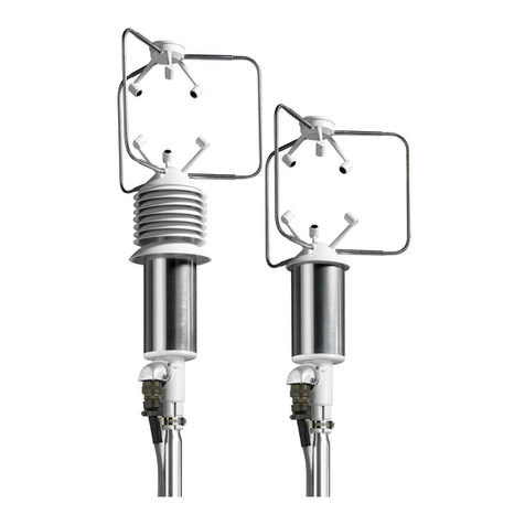
TP32MTT.03: Temperature probe equipped with seven Pt100 1/3 DIN
sensors for the measurement of temperature at depth: +5 cm, 0, -5
cm, -10 cm, -20 cm, -50 cm, -1 m with respect to the ground level,
according to the indications of the WMO. RS485 digital output with
MODBUS-RTU protocol. 8-pole M12 male connector. Power supply
6…30 Vdc. The CPM12-8P… cable must be ordered separately.
TP32MTT.03.1: Temperature probe equipped with six Pt100 1/3 DIN
sensors for the measurement of temperature at depth: +5 cm, 0, -5
cm, -10 cm, -20 cm, -50 cm with respect to the ground level, according
to the indications of the WMO. RS485 digital output with MODBUS-
RTU protocol. 8-pole M12 male connector. Power supply 6…30 Vdc.
The CPM12-8P… cable must be ordered separately.
CP24: PC connecting cable for the conguration of the MODBUS
parameters. With built-in RS485/USB converter. 8-pole M12 connector
on probe side and USB A-type connector on the PC side.
CPM12-8P.2: 8-pole cable. Length 2 m. 8-pole M12 connector at one side,
open wires on the other side.
CPM12-8P.5: 8-pole cable. Length 5 m. 8-pole M12 connector at one side,
open wires on the other side.
CPM12-8P.10: 8-pole cable. Length 10 m. 8-poles M12 connector at one
side, open wires on the other side.
TP32MTT.03A: Accessory to perform the hole in the soil to insert the
probe.
TP32MTT.03B: Accessory for signaling the presence of the probe.
