M
A
X
M
I
N
HOL
D
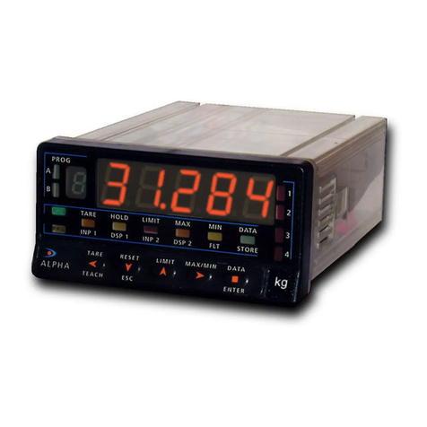
TARE
1
2
3
4
TARE
RESET
VISUAL
DATA
ESC
ENTER
LIMIT
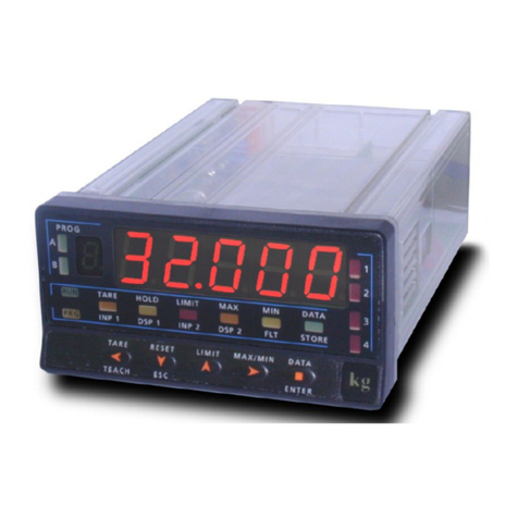
TARE KEY
Stores the actual value on
main display as a TARE
value for this actual
RESET KEY
Allow s to put to zero the value on
display, selected by VISUAL routine
LIMIT KEY
Shows at every push the
setpoint value if the
instrument is carrying a
setpoint option
AUXILIARY DISPLAY
Shows the TOTAL value.
MAIN DISPLAY
Shows the value of selected
channel
LED’s of setpoint
Show which relay is activated
LABEL
Engineering units
VISUAL KEY
Gets the ‘VISUAL’ routine
showing at every push, the
name and the value of
every selected channel
Key DATA
Access to programming mode.
LED HOLD
Shows that display is frozen
LED TARA
Shows that variable on main
display has a tare value in the
memory
1.2. Description of panel functions in mode (RUN)
6
7.2 TECHNICAL SPECIFICATIONS
Process Input
•Voltage input (pin 2 versus 3)..............±( 0-5/ 0-10)V
•Input Impedance.............................................1MΩ
•Voltage Input (pin 1 versus 3).........................± 0-1V
•Input Impedance ........................................ 100MΩ
•Current Input (both)................................ ±0-20 mA
•Input Impedance (both).................................11,8Ω
Load-Cell or mV Input
•Voltage input...............±30,±60,±120,±300,±500 mV
4-wires, unipolar or bipolar
Input Impedance......................................... 100MΩ
Potentiometer Input
•Min. resistance...............................................120Ω
•Excitation Voltage............................................2.2V
•Input Impedance (1 versus 3).......................>10 MΩ
Excitation
2,2 V @ 30 mA not adjustable.
24 V @ 30 mA not stabilized.
5 V ±100 mV @ 120 mA with fine adjust (50 ppm/ºC)
10 V ±10 mV @ 120 mA with fine adjust (50 ppm/ºC)
Display
•Main Display .........................................-9999/9999
•....................................... 5 red digits, 7 Segments
•Auxiliary Display.........................-9999999 / 9999999
•.............................................8 green digits 8 mm
•Decimal Point ............... Programmable (both displays)
•LED's................................8(Functions and outputs)
•Display Rate...................................................10/s
•................................................... 100/s (totalizer)
•Positive overflow ............................................ OVFr
•Negative overflow......................................... -OVFr
Conversion
•Technical......................................................... Σ∆
•Resolution................................................± 15 bits
•Rate............................................................200/s
•Resolution peak measure.............................±15 bits
Integrator
•Time base programmable ......................... s, m, H, D
•Integration rate ..........................................100/s
•Low cot-out ......................... all range programmable
Accuracy at 23ºC ± 5 ºC
•Error max. ........................±(0.1% reading +2 digits)
•Temperature coefficient..........................100 ppm/ºC
•Warming time........................................ 10 minutes
Power Supply
•KAPPA-M.......................... 230/115V ±10% 50/60Hz
•KAPPA-M2.............................24/48V ±10% 50/60Hz
•Consumption...........5W (without options), 10W (MAX)
•Fuses (DIN41661) Recommended (not supplied)
230/115 V AC ............................. F 0.2A/250V
24/48 V AC.................................. F 0.5A/250V
38
