manuals.online logo
Brands
  1. Home
  2. •
  3. Brands
  4. •
  5. Bartec
  6. •
  7. Measuring Instrument
  8. •
  9. Bartec 07-662 Series Quick start guide

Bartec 07-662 Series Quick start guide

Operational Instruction (Translation) Potentiometer Type 07-662.-…./….
BARTECGmbH Max-Eyth-Straße 16
97980 Bad Mergentheim
Germany
Tel.: +49 7931 597-0
Fax: +49 7931 597-119
[email protected]
www.bartec.de
Reservation Technical data subject to change without notice. Changes, errors and
misprints may not be used as a basis for any claim for damages.
EN 1/4
Explosion protection Technical data
Maximum Ex type of protection
Depending on the installations; observe the
specifications on the type label.
ATEX
Ex type of protection
II 2G
Ex d e IIC T6 resp. T5 Gb
II 2D
Ex tb IIIC T80 °C resp.
T95 °C Db
0044
Certification
EPS 14 ATEX 1 696
IECEx
Ex type of protection
Ex d e IIC T6 resp. T5 Gb
Ex tb IIIC T80 °C resp.
T95 °C Db
Certification
IECEx EPS 14.0042
INMETRO
Ex type of protection
Ex d e IIC T6…T5 Gb
Ex tb IIIC T80 °C…T95 °C Db
Certification
NCC 14.02943
Certification
TC RU C-DE.ГБ06.В.00443
Ambient temperature range
Depending on the installations; observe the
specifications on the type label.
-20 °C up to max. +70 °C
(-4 °F up to max. +158 °F)
Approved for zones
1, 2 and 21, 22
Electrical data
Rated voltage: up to 250 V
Power loss: max. 8 W
Protection class
Max. IP 66 (EN 60529)
Mechanical strength
Impact energy: max. 7 Nm
Rotation, electrical/mechanical
Cemented wire-wound resistors:
Type 07-662.-.111-….: 250/ 270
Carbon-film resistors on ceramic:
Type 07-6622-.113-….: 270
Precision wire-wound resistors:
Type 07-6622-.112-….: 1 turn
320±2°
Type 07-6624-.102-….:
10 turns
10 x 360°
+10°
Enclosure material
– Stainless steel
– Brass, surface bare/nickel-plated
Dimensions
See page 3.
07-6620-7D0002/A-02/15-STVT-381059
Note on instructions
When working in hazardous areas, the safety o
f
personnel and equipment depends on compli-
ance with the relevant safety regulations. The
people in charge of installation and mainte-
nance bear a special responsibility. It is essen-
tial that they have an exact knowledge of the
applicable rules and regulations.
The instructions provide a summary of the most
important safety measures and must be read by
everyone working with the product so that they
will be familiar with the correct handling of the
product.
The instructions have to be kept for future
reference and must be available throughout the
expected life of the product.
Description
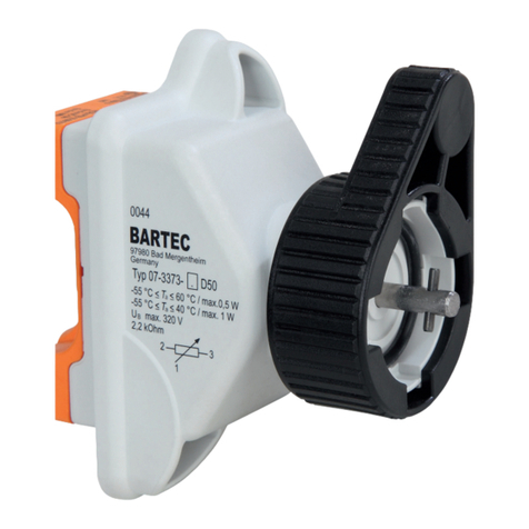
The type 07-662.-…./…. potentiometer consists
of a metal Ex d enclosure, into which an inser-
tion potentiometer is fitted.
The metal Ex d enclosures are tailored to the
dimensions of the resistors and will be pro-
duced in different sizes from Ø 30 to 60 mm
(1.18 to 2.36 in).
The potentiometer can be fastened and secured
against twisting in a number of ways. Two nuts
are included in each consignment. Optionally
BARTEC provides either threaded holes in the
front panel of the enclosure or an antirotation
pin.
Accessories, such as rotary and pointer knobs,
scales, digital drives for 10 turns potentiometer,
and slip clutches could be delivered.
Operational Instruction (Translation) Potentiometer Type 07-662.-…./….
BARTECGmbH Max-Eyth-Straße 16
97980 Bad Mergentheim
Germany
Tel.: +49 7931 597-0
Fax: +49 7931 597-119
[email protected]
www.bartec.de
Reservation Technical data subject to change without notice. Changes, errors and
misprints may not be used as a basis for any claim for damages.
EN 2/4
07-6620-7D0002/A-02/15-STVT-381059
Safety instructions
The potentiometer may be used only within the
specified temperature class and the tempera-
ture range indicated for it (see type label).
The potentiometer is not suitable for use in
zones 0/20.
The potentiometer may be operated only if it is
clean and not damaged in any way. Dus
t
deposits exceeding 5 mm (> 0.2 in) must be
removed.
Utilization in areas other than those specified
and the opening or modification of the product
by anyone other than the manufacturer are not
permitted and will exempt BARTEC from liabil-
ity for defects and any further liability.
The generally applicable statutory rules and
other binding directives relating to workplace
safety, accident prevention and environmental
protection must be observed.
When using electrical systems, the relevant
installation and operating conditions must be
observed. The specifications on the type label
must be adhered to.
Observe the applicable laws and directives
when commissioning or restarting operation.
Always follow the safety instructions on the
operating equipment.
Marking
Particularly important points in these instruc-
tions are marked with a symbol:
DANGER indicates a hazardous situation
which, if not avoided, will result in death o
r
serious injury.
WARNING indicates a hazardous situation
which, if not avoided, could result in death o
r
serious injury.
CAUTION indicates a hazardous situation
which, if not avoided, could result in minor o
r
moderate injury.
NOTICE is used to address practices not
related to personal injury.
Note
Important instructions and information on
effective, economical and environmentall
y
compatible handling.
Standards conformed to
EN 60079-0:2012/IEC 60079-0 : 2011
EN 60079-1:2007/IEC 60079-1 : 2007-04
EN 60079-7:2007/IEC 60079-7 : 2006-07
EN 60079-31:2009/IEC 60079-31 : 2008
ABNT NBR IEC 60079-0
ABNT NBR IEC 60079-1
ABNT NBR IEC 60079-7
ABNT NBR IEC 60079-31
as well as
EN 60204-1:2006/IEC 60204-1:2005, mod.
EN 62208:2011/IEC 62208:2011
EN 60445:2010/IEC 60445:2010
EN 60529:1991 + A1:2000 + A2:2013/
IEC 60529:1989 + A1:1999 + A2:2013
Transport, storage
Damage to the potentiometer through incor-
rect transport or incorrect storage.
Transport and storage is permissible in
original packaging only.
Assembly / disassembly
Risk of serious injury due to incorrect
proceedings.
Only authorized and qualified personnel
may do any of the assembly, disassembly,
installation and commissioning work.

A
lways disconnect the device from voltage
before assembly/disassembly.
When assembling the device, take care that the
distances between the outside edge of the
flame-proof gap and the fixed obstacles that
are not part of the device are for:
Gas/vapour sub-group
IIC IIB
at least 40 mm
(1.58 in)
at least 30 mm
(1.18 in)
The potentiometer must be fitted into an enclo-
sure that conforms to the requirements of a
type of protection recognized as being in ac-
cordance with IEC/EN 60079-0.
When fitting into an enclosure with “Ex e” type
of protection the clearance and creepage
distances under IEC/EN 60079-7 Section 4.3,
Section 4.4 and Table 1 must be observed.
Installation
Death or serious injury due to improper use.
Extensions or modifications to the potenti-
ometer are only permissible if the manufac-
turer’s approval is obtained first.
The IEC/EN60079-14 must be observed.
Check at the installation:
When connecting cables and conductors
to operating equipment with the “Ex e”
type of protection, use Ex-certified cable
entries that are suitable for the respective
types of cables and conductors. They
must conform to the “Ex e” type of protec-
tion and have a suitable sealing element
uphold the device’s protection class.
Connect metallic cable entries to the
earthing system.
Seal unused cable entry holes with Ex-
certified stopping plugs.
When connecting directly to the flame-
proof enclosure, use Ex-certified entries
that are suitable for the enclosure capaci-
ty, the gas sub-group and the conductor.
Take care when connecting conductors:

A
lways use suitable crimping tools when
crimping the wire-end ferrules to ensure a
consistent quality of pressing each time.
Take care not to damage the individual
wires.
Tighten all terminal points securely (in-
cluding those not in use).
Commissioning
Before commissioning, check that:
The device has been installed in compli-
ance with regulations.
The device is not damaged.
The connection has been established
properly.
All screws have been tightened securely.
The device functions perfectly.
Operation
Death or serious injury through improper
use.
The potentiometer may be operated only
within the technical limits that apply to it
(see page 1).
Operational Instruction (Translation) Potentiometer Type 07-662.-…./….
BARTECGmbH Max-Eyth-Straße 16
97980 Bad Mergentheim
Germany
Tel.: +49 7931 597-0
Fax: +49 7931 597-119
[email protected]
www.bartec.de
Reservation Technical data subject to change without notice. Changes, errors and
misprints may not be used as a basis for any claim for damages.
EN 3/4
07-6620-7D0002/A-02/15-STVT-381059
Maintenance and fault clearance
Death or serious injury through damaged
flameproof encapsulation.
Replace defective parts in the flameproo
f
encapsulation with original parts immedi-
ately.
Risk of serious injury due to incorrect
proceedings.
Only authorized qualified personnel may
do any of the work relating to maintenance
and fault clearance.
IEC/EN 60079-17 must be observed. It is
recommended to formulate a maintenance
plan according to this standard.
Maintenance work
The operator of the potentiometer must keep it
in good condition, operate it correctly, monitor it
and clean it regularly.
Visually inspect the threaded gap.
Visually inspect the flameproof encapsu-
lation for damage.
Note
In the course of maintenance particular atten-
tion must be paid to checking that the parts
essential for the type of protection and prope
r
functioning are in good condition.
Fault clearance
The potentiometer is defective if the flameproo
f
encapsulation is damaged and/or if one of the
components does not function any longer
In this case:
Replace defective parts in the flameproo
f
encapsulation with original parts immedi-
ately.
Replace or repair the defective compo-
nents with original parts.
Note
Follow the components mounting instruc-
tions/operating instructions to replace or repai
r
the components.
Accessories, spare parts
See BARTEC catalogue.
Disposal
The potentiometer components contain metal
and plastic parts.
The statutory requirements for disposing o
f
electronic scrap must be observed therefore
(e.g. disposal by an approved disposal compa-
ny).
Service address
BARTEC GmbH
Max-Eyth-Straße 16
97980 Bad Mergentheim
Germany
Tel.: +49 7931 597-0
Fax: +49 7931 597-119
Dimensions
Selection chart
Order number Temperature
class Max. power
loss a
in mm (in) b
in mm (in) c
in mm (in) d
in mm (in) e Overall length f
in mm (in)
07-6622-.111/…. T6 2.5 W
Ø 30 (1.2)
55 (2.2)
Ø 6 (0.2) 11 (0.4) M12x1.5
66 (2.6)
07-6622-.112/…. T6 1.2 W 45 (1.8) 55 (2.2)
07-6622-.113/…. T6 2 W
07-6623-.111/…. T5 3 W 55 (2.2)
66 (2.6)
07-6624-.111/…. T6 5 W Ø 45 (1.8)
90 (3.5)
101 (4)
07-6624-.102/…. T6 2 W Ø 38 (1.5) 50 (2) Ø 6.35 (0.3) 8 (0.3) 3/8-32
UNEF 61 (2.4)
07-6625-.111/…. T5 6 W Ø 45 (1.8)
90 (3.5)
Ø 6 (0.2) 11 (0.4) M12x1.5
101 (4)
07-6626-.111/…. T6 7 W Ø 60 (2.4) 87 (3.4) 98 (3.9)
07-6627-.111/…. T5 8 W
Operational Instruction (Translation) Potentiometer Type 07-662.-…./….
BARTECGmbH Max-Eyth-Straße 16
97980 Bad Mergentheim
Germany
Tel.: +49 7931 597-0
Fax: +49 7931 597-119
[email protected]
www.bartec.de
Reservation Technical data subject to change without notice. Changes, errors and
misprints may not be used as a basis for any claim for damages.
EN 4/4
07-6620-7D0002/A-02/15-STVT-381059

This manual suits for next models

9

Other Bartec Measuring Instrument manuals

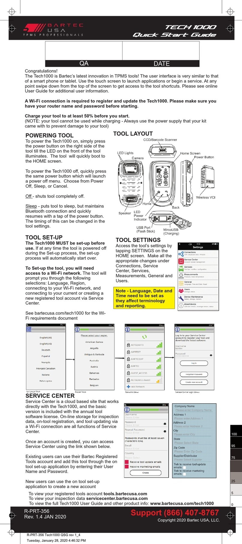
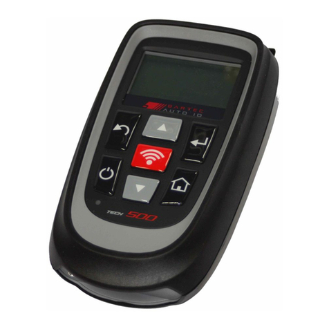
Bartec TECH 1000 User manual

Bartec

Bartec TECH 1000 User manual

Bartec Tech500 User manual

Bartec

Bartec Tech500 User manual

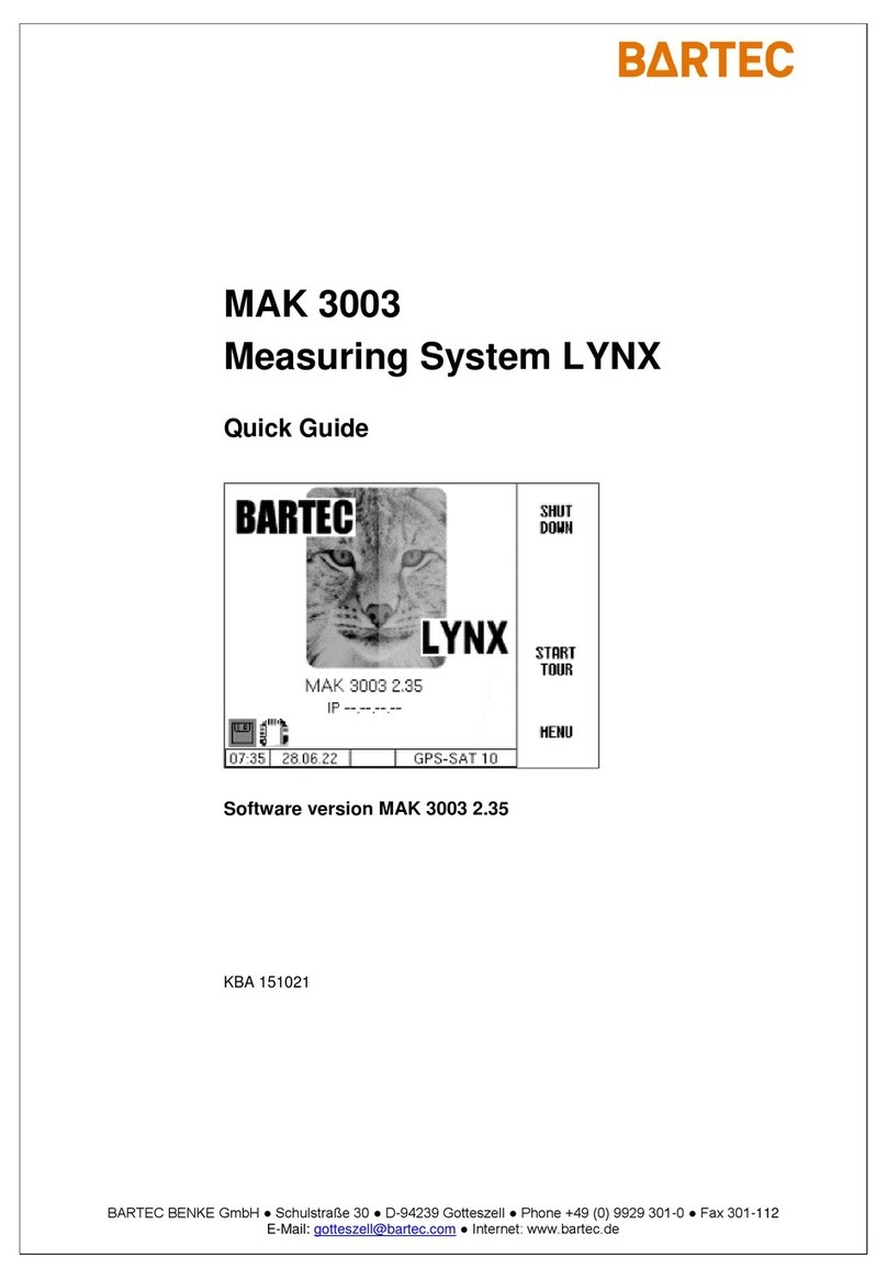
Bartec MAK 3003 User manual

Bartec

Bartec MAK 3003 User manual

Bartec MAK TIGER 3003 User manual

Bartec

Bartec MAK TIGER 3003 User manual

Bartec VOLUTANK Petro 3003 User manual

Bartec

Bartec VOLUTANK Petro 3003 User manual

Bartec ORB P-800LT User manual

Bartec

Bartec ORB P-800LT User manual

Bartec RDW 03 User manual

Bartec

Bartec RDW 03 User manual

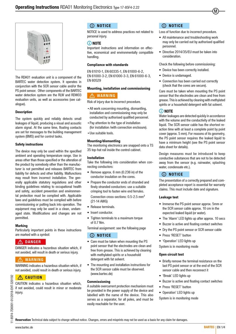
Bartec RDA01 User manual

Bartec

Bartec RDA01 User manual

Bartec ALCAR TECH600 User manual

Bartec

Bartec ALCAR TECH600 User manual

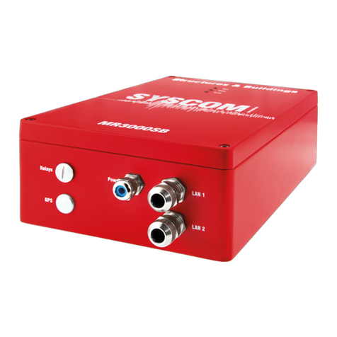
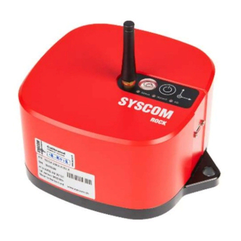
Bartec SYSCOM ROCK User manual

Bartec

Bartec SYSCOM ROCK User manual

Bartec TECH600PRO User manual

Bartec

Bartec TECH600PRO User manual

Bartec MR3000DMS User manual

Bartec

Bartec MR3000DMS User manual

Bartec Tech200 User manual

Bartec

Bartec Tech200 User manual

Bartec ComEx Flex Quick start guide

Bartec

Bartec ComEx Flex Quick start guide

Bartec P-600 User manual

Bartec

Bartec P-600 User manual

Bartec TECH450PRO User manual

Bartec

Bartec TECH450PRO User manual

Bartec Syscom MR3000 Series User manual

Bartec

Bartec Syscom MR3000 Series User manual

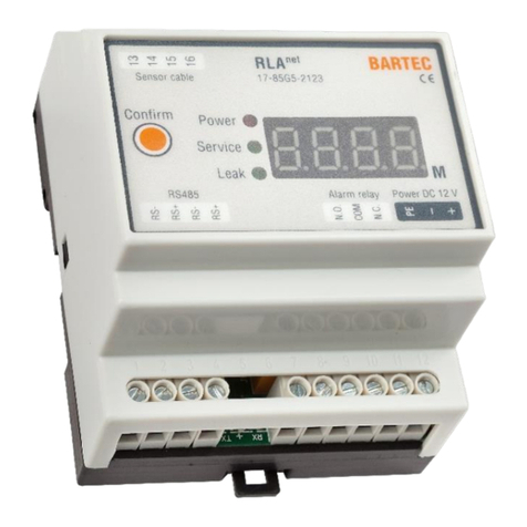
Bartec RLAnet 17-85G5-2123 Series Specification sheet

Bartec

Bartec RLAnet 17-85G5-2123 Series Specification sheet

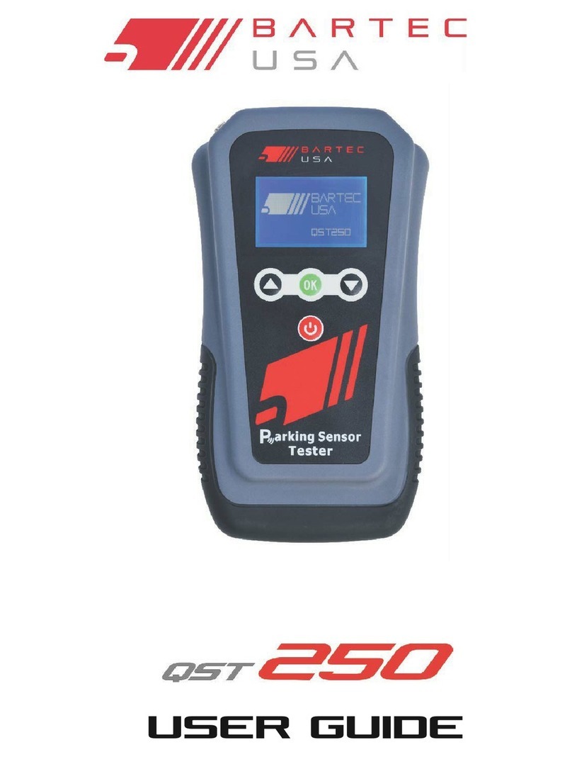
Bartec QST 250 User manual

Bartec

Bartec QST 250 User manual

Bartec Tech1000 User manual

Bartec

Bartec Tech1000 User manual

Bartec MAK TIGER 3003 User manual

Bartec

Bartec MAK TIGER 3003 User manual

Bartec TECH550PRO User manual

Bartec

Bartec TECH550PRO User manual

Bartec Tech200BT User manual

Bartec

Bartec Tech200BT User manual

Bartec HYGROPHIL H 4230-10 A Series User manual

Bartec

Bartec HYGROPHIL H 4230-10 A Series User manual

Popular Measuring Instrument manuals by other brands

König Electronic SEC-DVR202S manual

König Electronic

König Electronic SEC-DVR202S manual

Gemlogis BLEU quick start guide

Gemlogis

Gemlogis BLEU quick start guide

Hifonics TPS-MR1 Operator's guide

Hifonics

Hifonics TPS-MR1 Operator's guide

METREL MI 3205 instruction manual

METREL

METREL MI 3205 instruction manual

TriBrer TB-6 Series user guide

TriBrer

TriBrer TB-6 Series user guide

Water I.D. FT 40 manual

Water I.D.

Water I.D. FT 40 manual

ABB CoriolisMaster FCB100 Product guide

ABB

ABB CoriolisMaster FCB100 Product guide

Hanna Instruments HI 9219 instruction manual

Hanna Instruments

Hanna Instruments HI 9219 instruction manual

ABB DATUM L150 user guide

ABB

ABB DATUM L150 user guide

Raycus RFL-C30000XZ user guide

Raycus

Raycus RFL-C30000XZ user guide

Rish DELTA VAF NX operating manual

Rish

Rish DELTA VAF NX operating manual

Agilent Technologies 8614 B Series user guide

Agilent Technologies

Agilent Technologies 8614 B Series user guide

Goodwe HK3000 Quick Installation Instruction

Goodwe

Goodwe HK3000 Quick Installation Instruction

Cybertronix Sentinel EFI-BFZ user manual

Cybertronix

Cybertronix Sentinel EFI-BFZ user manual

TESTO 338 instruction manual

TESTO

TESTO 338 instruction manual

SMC Networks PFG3 0 Series Operation manual

SMC Networks

SMC Networks PFG3 0 Series Operation manual

Comet Commeter C0111 manual

Comet

Comet Commeter C0111 manual

IMI Rad 100 Operation manual

IMI

IMI Rad 100 Operation manual

manuals.online logo
manuals.online logoBrands
  • About & Mission
  • Contact us
  • Privacy Policy
  • Terms and Conditions

Copyright 2025 Manuals.Online. All Rights Reserved.