Delta-T Devices SM200 User manual
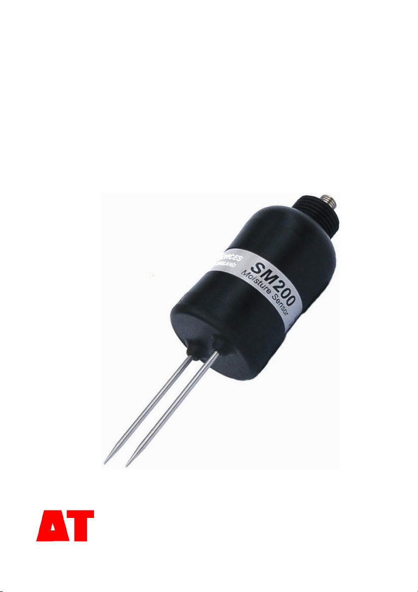
SM200
Soil Moisture Sensor
Quick Start Guide Version 1.3
Delta-T Devices Ltd
© 2005 Delta-T Devices Ltd Page 2
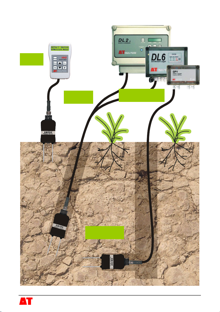
SM200 overview
1Cables
3HH2
4Data Loggers
2Installation
© 2005 Delta-T Devices Ltd Page 3
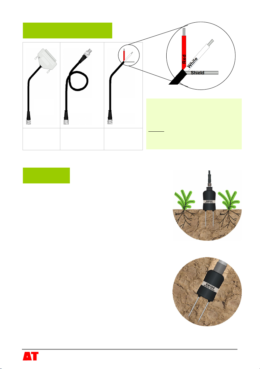
1 Cables and Accessories
1.1m
5m
10m
25m
5m bare end
Insertion rods are available for installing the SM200 in an augered hole.
2 Installation
Surface installation and spot measurements
Clear away any stones. Pre-form holes in very hard
soils before insertion.
Push the SM200 into the soil until the rods are fully
inserted. Ensure good soil contact. Best results are
achieved by inserting the SM200 horizontally.
If you feel strong resistance when inserting the
SM200, you have probably hit a stone. Stop, and re-insert at a new location.
Installing at depth
Auger a 45mm diameter hole. ~10° to vertical is
recommended.
Fit insertion rod to SM200 - remember to pass the
cable through the insertion rod and fit the connector
first.
Push the SM200 into the soil until rods are fully
inserted. Ensure good soil contact.
Backfill around the insertion rod.
Alternatively
Dig a trench, and install horizontally (see overview diagram).
HH2
cable
Extension
cables
Logger
cable Extension cables can be joined up to
a recommended maximum of 55m.
Align the connectors carefully
before pushing parts together.
Screw together firmly to ensure the
connection is water-tight.
Power V+
Si
g
nal
Ground
© 2005 Delta-T Devices Ltd Page 4
Device:
vSM200
Soil Type:
vMineral
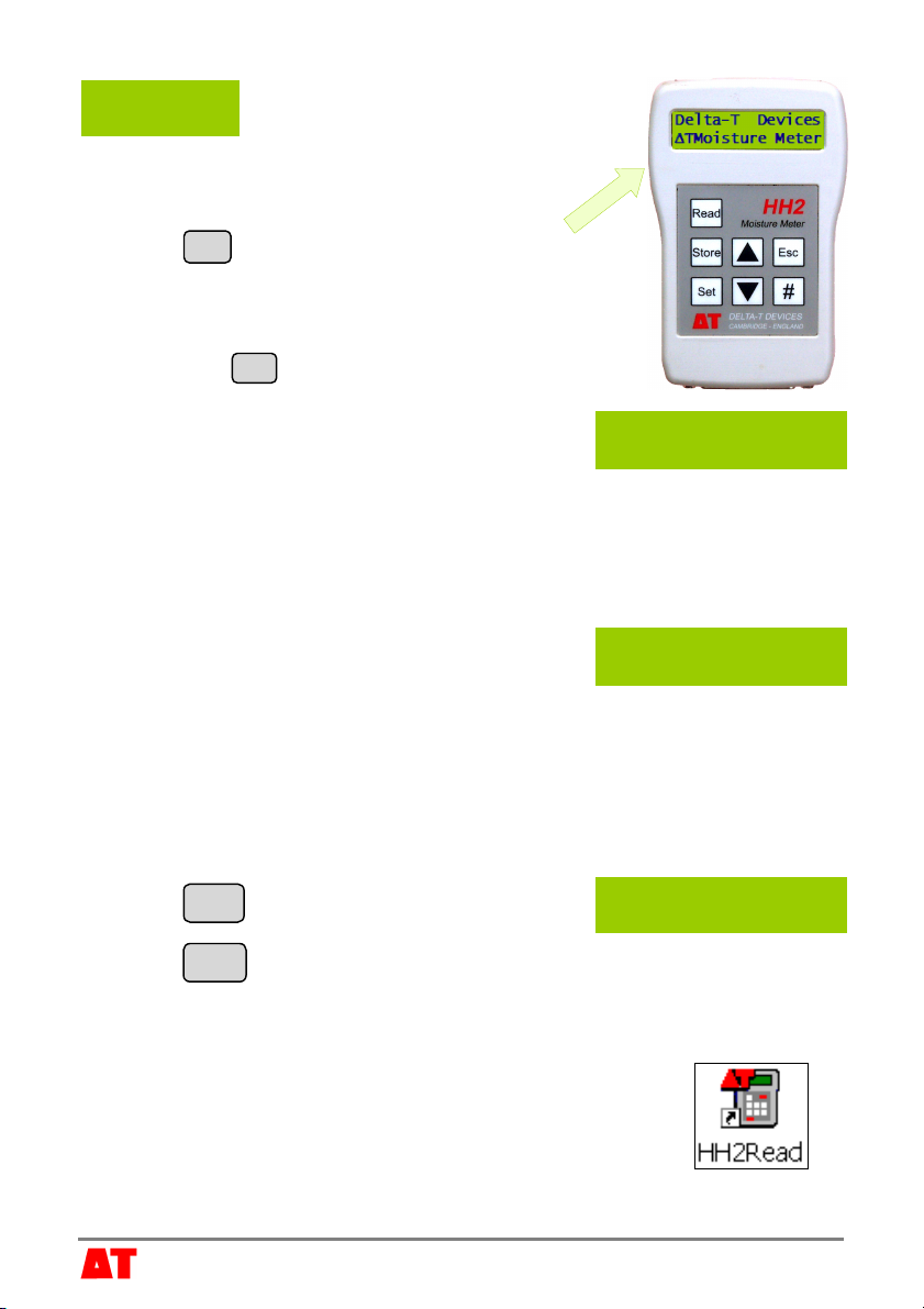
3 HH2 Meter
Connect the SM200 to the HH2 meter.
Press Esc to turn the meter on, and if necessary
press again until the HH2 displays the start-up screen.
Set the meter to read from an SM200:
►Press Set and scroll down to the Device option.
►Press Set again and scroll down to select
SM200.
►Press Set to confirm this choice.
Make sure the HH2 is correctly configured for your soil type:
►At the start-up screen, press Set and scroll down to the Soil Type option.
►Press Set again and scroll down to the appropriate soil type (use Mineral
for sand, silt or clay soils or Organic for peaty
soils)
►Press Set to confirm this choice.
Choose the units you want for displaying readings.
►At the start-up screen, press Set and scroll down to the Display option.
►Press Set again and scroll down to select units.
►Press Set to confirm this choice.
Press Read to take a reading.
Press Store to save or Esc to discard the reading.
Remove the SM200 from the soil and move to a new location...
If you have saved data, connect your HH2 to a PC and run
HH2Read to retrieve the readings.
SM200 Store?
20.3%vol
© 2005 Delta-T Devices Ltd Page 5
4 Data Loggers
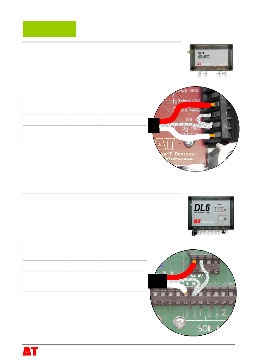
GP1
2 SM200s can be connected to each GP1 - the SM200
should be connected as a single-ended, powered sensor.
These details illustrate connections for Channel1:
SM200 wiring Colour GP1 terminal
Power V+ Red CH1 (PWR)
Signal White
CH1 (+)
Ground Shield
CH1 (GND)
and CH1 (-)
Configure the GP1 by choosing “SM200”
from the sensor menu in PC DeltaLINK or
Pocket DeltaLINK.
For configuration details see the GP1 Quick Start Guide.
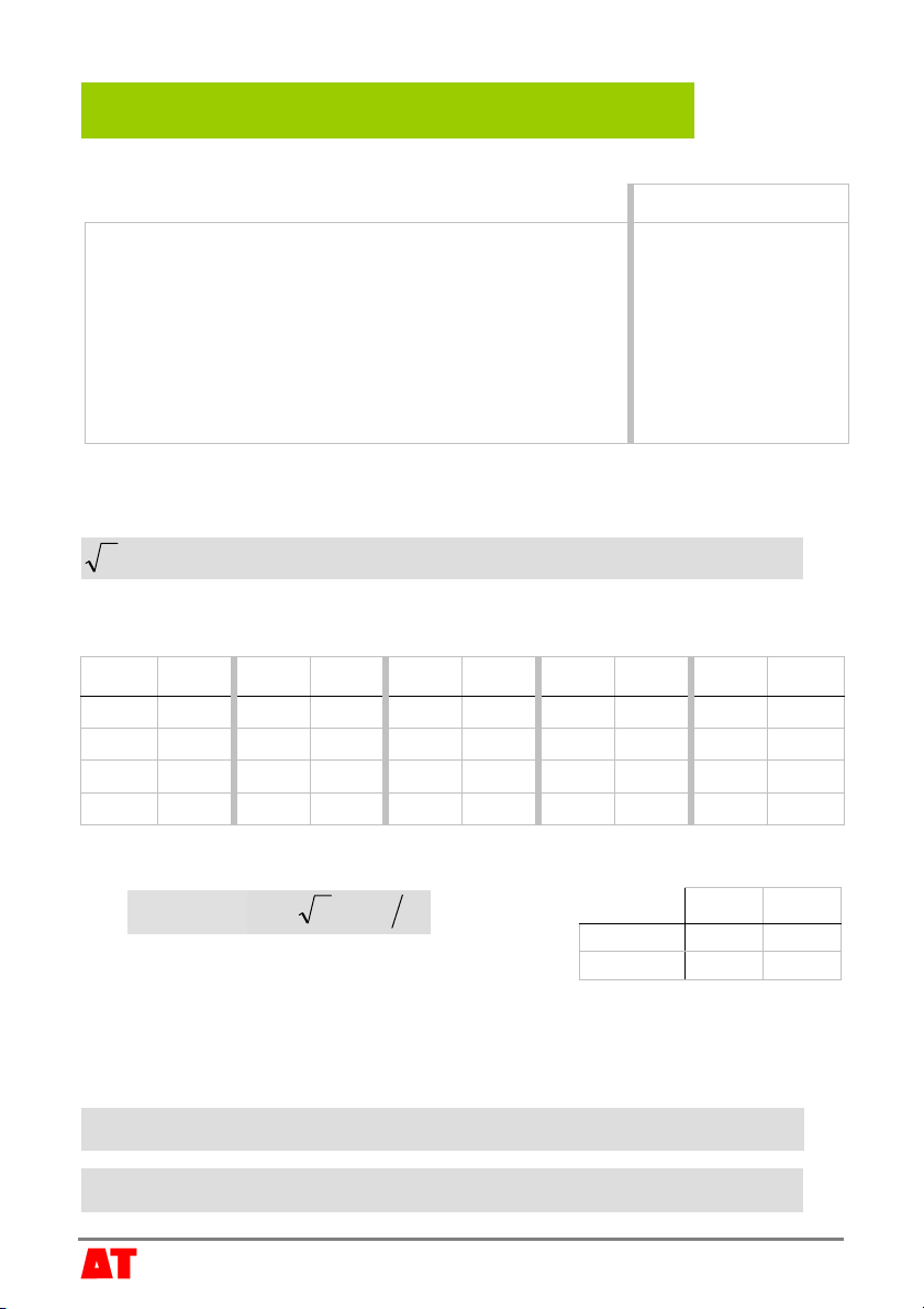
DL6
Up to 6 SM200s can be connected to each DL6 with each
sensor connected as a single-ended, powered sensor.
These details illustrate connection to Channel1:
SM200 wiring Colour DL6 terminal
Power V+ Red V+
Signal White
IN+
Ground Shield
IN-
and 0V
Configure the DL6 by choosing “SM200”
from the sensor menu in DeltaLINK.
For configuration details refer to the DL6 User
Manual.

© 2005 Delta-T Devices Ltd Page 6
DL2e
Up to 60 SM200s can be connected to each DL2e with
each sensor connected as a single-ended, powered
sensor.
These details illustrate connection to Channel 58 using
the LAC1 input card configured in 15-channel mode,
and warm-up channel 63:
SM200 wiring Colour DL2e terminal
Power V+ Red 63 NO
Signal White
58+
Ground Shield
58-
and 61-
Configure the DL2e by choosing one of the
SM200 sensor codes from the LS2Win
sensor library, according to your soil type.
For configuration details see the DL2e User Manual.
Other data loggers
The SM200 should be connected as a single-ended, powered sensor.
Configure the logger input as a voltage sensor, approximately 0 to 1.0 volts
corresponding to ~0 to 60% water content – see next section.
The SM200 has
been optimised for
a 1 second warm-
up period
(minimum period
200ms).
It is recommended
that the sensor is
not powered
continuously.
© 2005 Delta-T Devices Ltd Page 7
a0a1
Mineral 1.6 8.4
Organic 1.3 7.7
Example
Take a reading with the SM200 V= 0.294 volts
either
Convert the reading to √ε using the polynomial or
linearisation table below. √ε = 3.62
Then convert √ε to soil moisture, θ, using the soil
calibration values (a0, a1). θ= 24.0%
or (for mineral soil)
Convert directly for mineral or organic soils θ= 24.0%
5 Convert SM200 voltages to soil moisture readings
Note: The SM200 output is automatically converted to soil moisture when using an
HH2 meter or Delta-T data loggers.
Conversion to √ε
Polynomial (use for SM200 readings from 0 to 1.1 Volts)
5432 536.13032.46881.60725.38103.160.1 VVVVV +−+−+=
ε
where Vis the SM200 output in volts
Linearisation table (use for SM200 readings from 0 to 1.2 Volts)
V√ε V√ε V√ε V√ε V√ε
0.000 1.011 0.120 2.461 0.260 3.442 0.820 5.936 1.150 7.661
0.030 1.447 0.150 2.718 0.310 3.700 0.960 6.586 1.200 8.039
0.060 1.832 0.180 2.946 0.400 4.105 1.040 6.991 1.220 8.264
0.090 2.168 0.220 3.211 0.600 4.953 1.100 7.333 1.800 9.000
Conversion from √ε to Soil Moisture
Soil moisture
(
)
10 aa−=
εθ
Use these generalised soil calibration values for
mineral and organic soil types, or carry out a soil-
specific calibration to derive your own values – see SM200 User Manual.
Multiply x100 to convert soil moisture from m3.m-3 to % volumetric.
Direct conversion for Mineral and Organic soils
5432
mineral 611.148.5248.761.4917.1071.0 VVVV +−+−+−=
θ
5432
organic 758.1978.5907.7029.5091.2039.0 VVVVV +−+−+−=
θ

6 Specifications
* Accuracy figures apply to calibration soils and over 0 to 60°C.
Percentages quoted as %vol are % volumetric water content.
7 Care and Safety
Notices
All parts of the SM200 design and documentation are the exclusive property of Delta-T
Devices and covered under international copyright law, © 2005. Patent(s) pending.
The SM200 product is CE compliant, conforming to EN61326:1997.
Delta-T Devices Ltd
128 Low Road
Burwell
Cambridge CB5 0EJ
England (UK)
Tel: +44 1638 742922
Fax: +44 1638 743155
E-mail: [email protected]
Web: www.delta-t.co.uk
The rods of the SM200 are sharp in order to ease insertion. Care must be
taken and handling precautions followed.
Avoid touching the rods or exposing them to other sources of static damage.
Keep the SM200 in its protective tube when not in use.
Take care when attaching cables to ensure that the connectors are clean,
undamaged and properly aligned before pushing the parts together.
Screw together firmly to ensure the connection is water-tight. If the connector
is damaged, apply a light smearing of silicon grease to maintain sealing.
Do not pull the sensor out of the soil by its cable.
If you feel strong resistance when inserting the SM200 into soil, it is likely you
have encountered a stone. Stop pushing and re-insert at a new location.
Range and Notes
Accuracy* ±3 %vol 0 to 50 %vol
Salinity errors ± 3.5 %vol 0 to 40 %vol, over 50 to 500 mS.m-1
(0.5 to 5 dS.m-1)
Power requirement 5 to 14V
15mA typical
1 second warm-up recommended
200ms minimum
Output signal 0 to 1.0V Nominal 0 to 60 %vol
Environmental sealing IP68 Sensor buriable, sealed to IP68
Operating range -20 to +60°C Readings in frozen soil are not meaningful
Table of contents
Other Delta-T Devices Accessories manuals


