Delta-T Devices GP1 User manual

Irrigation Control
Using Soil Moisture Sensors
Quick Start Guide
Version2c
Delta-T Devices Ltd

© 2010 Delta-T Devices Ltd Page 2
Overview
Potential benefits of sensor control
Reduced water use
Compact plants
Fewer weeds
Reduced labour for watering, pruning and weeding
Plants are less soft so establish more reliably
More fruit and flowers, less vegetative growth
Irrigation Timer
GP1
Solenoid
Valve
Moisture
Content
Timer control
Sensor control

© 2010 Delta-T Devices Ltd Page 3
This guide explains how to adapt timer-based irrigation control systems to include
soil moisture sensing using the
GP1
irrigation monitor and
SM300
soil moisture
sensor. The instructions are particularly directed at container-grown plants, but can
be applied to other shallow-rooting crops in free-draining compost or soil.
System Requirements
Check through this list carefully to make sure your system is
compatible:
Overhead or drip irrigation
- Capillary, sand bed or flood and drain systems switch off too slowly for
accurate moisture control
Reasonably uniform irrigation system
- The Coefficient of Uniformity (CU) should be > 80% for you to get the most
benefit from the system (otherwise you will have to routinely over-water to
prevent the less irrigated plants from drying out).
Plant pots, grow bags, mineral wool slabs etc. > 0.8 litre volume
- The SM300 can be set to control
irrigation in smaller pots but it may
be difficult to insert with sufficient
distance (~2cm) from the edge of
the pot.
The timer-based irrigation system
controls irrigation by solenoid
valves
- The relay cannot be used for direct
pump control
If you plan to control irrigation for a
mixed bed, the plants must have
similar water requirements.

© 2010 Delta-T Devices Ltd Page 4
Preparation
You need to assemble the following equipment:
Item
Accessories / notes
GP1
Mounting kit (GP1-MP1)
Serial cable, small screwdriver and PC software on
CD (included with GP1)
SM300
Logger cable (SMSC/sw-05)
Extension cables may be required (see section 1.1)
Note that the SM300 includes a built-in temperature
sensor but this can only provide soil / substrate
temperature readings when the SM300 is fully buried.
Cable to solenoid
Round cross-section 2-core wire
3-way
connector
block
You will need to put the connector block into a
sealed box if connecting to the solenoid valve in a
wet area.
Tape and/or cable ties
For keeping wires tidy and preventing accidents.
These may also be helpful:
SM300 + HH2
Useful for checking range of moisture contents
during set up and adjustment. Note that the HH2
does not display readings from the SM300 temperature
sensor.
You will also need access to the following:
Tools
Wire cutters & wire strippers…
An electrical multi-meter with audible short circuit
warning is also very useful.
Ladder
If some of the wiring will run overhead.
Portable computer
with Windows 98, XP,
Vista or 7
For configuring the GP1.
It is even more convenient to do this with an iPAQ
(see section 7), but check for compatibility.

© 2010 Delta-T Devices Ltd Page 5
Installation
1Install the SM300
1.1 Plan cable runs
Locate the solenoid valve that controls the bed irrigation.
Plan where to splice into the cable to the valve, and then
consider where it makes sense to mount the GP1.
Depending on available extension cables, this will then
determine the general location for the SM300.
1.2 Choose a location for the SM300
If there’s more than one type of plant within the bed,
choose a variety that uses more water.
Choose a representative plant i.e.
- Not in the outside row
- Moderate growth
- Foliage won’t shed water unduly
- No voids in the growing media
Check the water content of potential control plants using an SM300 and HH2 if
available, otherwise by lifting the pots or feeling the compost. Avoid plants that
appear to be unusually dry or wet.
1.3 Insert SM300 into pot / soil
Screw the cable onto the sensor (attach the extension cable first if you are using
one, otherwise directly attach the logger cable which terminates in bare wires).
Make sure the connectors halves are clean and aligned before pushing together,
then push them fully home and tighten to maintain the seal.
Insert the SM300 into the pot as close to the centre as
reasonably possible –see illustration above. Once inserted,
don’t joggle the sensor as this will create air gaps around the
measurement rods. You may find it useful to tape the cable to
the side of the pot.
Refer to the SM300 Quick Start Guide for more detail:

© 2010 Delta-T Devices Ltd Page 6
2Connect the GP1
2.1. Mount GP1 on post
Open the GP1 cover and attach to the
mounting plate using the 4 screws provided.
Then fix the mounting plate to a suitable post
either using cable ties, tape or U-bolts
(provided).
2.2. Connect cables to GP1
Pass the cable from the SM300 through the cable gland and connect to Channel 1
as shown (order for channel 1 is red, grey, white, black, green and blue):
Connect the cable for controlling the solenoid valve to the relay as shown (note the
colours of your cable will likely be different but the orientation of the connection is
unimportant). Don’t connect the other end to the solenoid valve at this stage.
Tighten the cable glands, replace the GP1 cover, secure all cables to the post and
tape carefully over any cable runs in walkways.
Refer to the GP1 Quick Start Guide if you want to connect the
SM300 temperature sensor or need more detailed instructions.
© 2010 Delta-T Devices Ltd Page 7
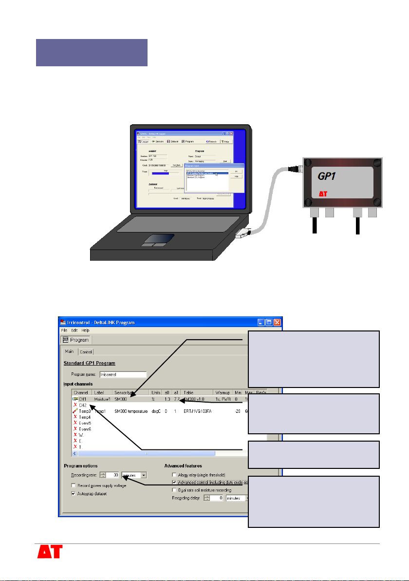
3Configure the GP1
3.1. Connect laptop to GP1
These instructions assume you’ve already fully installed the DeltaLINK software - if
not, you should refer to the GP1 Quick Start Guide.
Connect your laptop to the GP1. Start DeltaLINK and select File, New,
Program….From the list choose Standard GP1 Program.
3.2. Set up the GP1 recording program
Double-click and select the
SM300 sensor type for
Channel 1. In this example the
SM300 moisture reading has
been labelled “Moisture1”.
Select Organic for the Soil
type unless you are using
John Innes compost.
Click on other channels if you
have more sensors to connect.
Set the recording interval.
Note: this also sets how often
the GP1 checks whether to
turn the irrigation ON.
© 2010 Delta-T Devices Ltd Page 8
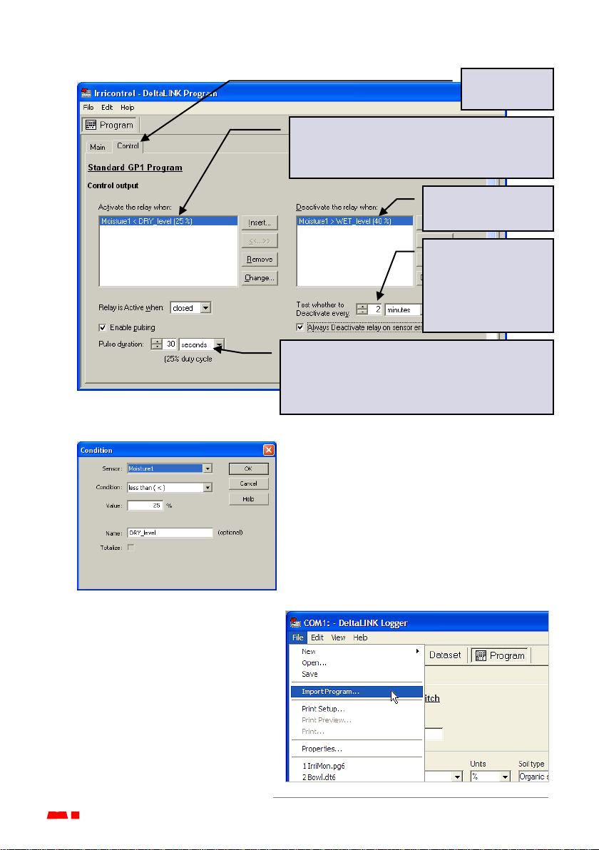
3.3. Set moisture control levels and pulse irrigation
3.4. Adjustable thresholds
When setting the control conditions, it is
useful to give a name to the threshold level
(“DRY_level” in this example). You will then
be able to adjust the thresholds later without
starting and stopping the program (this
feature requires DeltaLINK version 2.4 or
later).
3.5. Configure the GP1
Save the program and close the
program editor.
In the main DeltaLINK window,
select the Program view and click
on the Change button.
Select File, Import Program…,
and select the program file (.pg6)
that you have just saved.
Switch to the
Control tab.
Click on Insert... and select Moisture1 to
control irrigation ON with an appropriate
moisture threshold (see next section, 3.4).
Set the OFF
conditions similarly.
Set the GP1 to
check the OFF
conditions more
often than the
recording rate.
If Duty cycle < 100% the GP1 will pulse the
irrigation so that the compost has time to wet
up. In this example the irrigation would be
pulsed ON for 30 seconds every 2 minutes.

© 2010 Delta-T Devices Ltd Page 9
4Check the system
4.1. Check the SM300 readings and relay operation
In the main DeltaLINK window, select the Sensor view. Click on Read now and
check that the SM300 is giving sensible readings.
By withdrawing and re-inserting the SM300 partially from the soil/compost you can
simulate drying/wetting and check the relay operation as in this (rather artificial)
example.
Note: you should be able to hear the GP1 relay switching, but it may be
convenient to attach a multi-meter to the end of the control cable, so that you can
check the switching remotely.
When finished, click on Cancel to stop the readings, and if you have been
checking the readings by withdrawing the SM300, re-insert it in a new hole.
Moisture level () falls below set
level (25%), ON condition () is
triggered, and control relay ()
switches on.
Moisture level rises above 25%,
so ON condition is no longer
met, but irrigation will continue
until OFF condition is met.
Moisture level rises above 40%,
OFF condition () is met and
control relay () switches off.
© 2010 Delta-T Devices Ltd Page 10
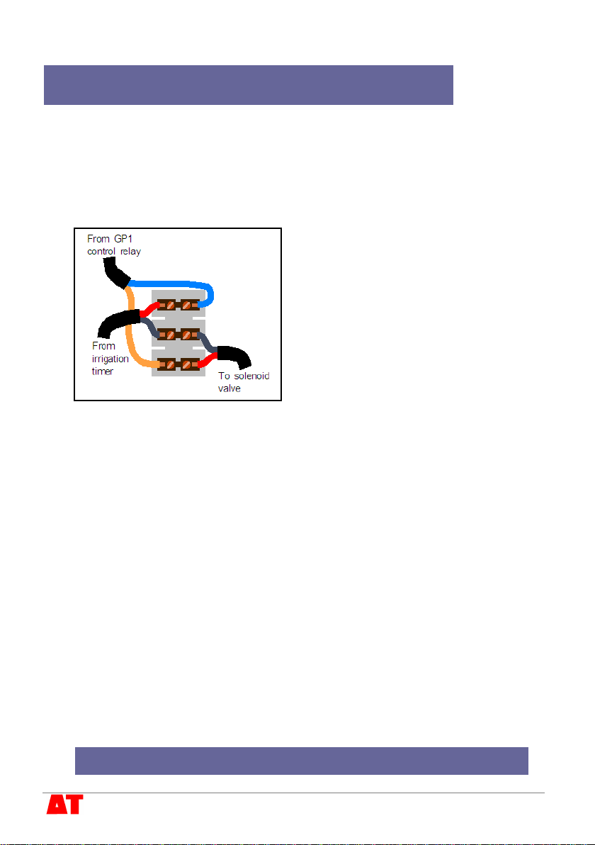
5Connect the solenoid valve and start irrigation
5.1. Connect the solenoid valve
Turn off irrigation to the bed. Cut the cable from the irrigation timer to the solenoid
valve and splice in the cable from the GP1 control relay using the connector block
as shown below. You will need to mount the block in a small waterproof enclosure
if the connection is likely to get wet.
Note: cable colours are likely to be different from this illustration.
5.2. Adjust the irrigation timer
Adjust your irrigation timer to water for longer periods.
The SM300 and GP1 will prevent your irrigation system from over-watering, so you
can safely increase the irrigation times. The sensor control will attempt to switch
the irrigation ON soon after the moisture level falls below the lower threshold
(depending on the time set in the recording rate) so it is important that the timer
allows irrigation to start within a reasonable time.
If you are watering by drip irrigation you may want to adjust the timer to irrigate
continuously throughout the day, leaving all the control to the SM300 and GP1.
5.3. Start irrigation control
Connect your laptop to the GP1, start DeltaLINK, and in the main Logger view
click on Start.
Turn on your irrigation system.
Your irrigation system is now under sensor control

© 2010 Delta-T Devices Ltd Page 11
6Adjust the settings
6.1. Check recorded
data
Connect your laptop to
the GP1, start
DeltaLINK and select
Dataset. The GP1 will
automatically download
the stored data and
display the soil moisture
readings as a graph
(this example shows a
GP1 with 2 SM300s
and a temperature
sensor):
To save the data, select File, Save and enter a name for your data.
6.2. Adjust irrigation levels
If you want to adjust an
irrigation control level, in the
main Logger view click on
Change... and adjust the
threshold value in the
Program setting window that
opens up. Click OK to apply
the change.
7Pocket DeltaLINK
The GP1 can also be configured using the Pocket PC
version of DeltaLINK. This provides exactly the same
facilities for programming the logger and examining the
stored readings, but is even more convenient for field use.
Pocket DeltaLINK requires a pda running Pocket PC
version 4.2 or later and an RS232 serial port for
connection to the GP1.

Notes
Battery use: the GP1 battery can be changed quickly without losing program settings
or data, but no readings will be taken and no control of irrigation will occur while the
battery is removed.
A standard PP3 alkaline battery will power the GP1 and SM300 for more than 4 months
when recording at 30 minute intervals. Check the battery voltage from time to time in
DeltaLINK and replace when below 6 Volts. See the GP1 Quick Start Guide for
further detail.
Sealing: the SM300, GP1 and all connectors are sealed to an appropriate standard,
but to maintain this sealing you should:
Take care when attaching cables to ensure that the connectors are clean,
undamaged and properly aligned before pushing the parts together. Screw
together firmly to ensure the connection is water-tight.
Ensure that all cable glands and cover screws are fully tightened.
Where possible avoid placing the GP1 directly underneath irrigation nozzles.
Replace the GP1 desiccant bags annually.
Status LED: the GP1 LED flashes twice every 10 seconds when it is logging normally.
It will flash four times instead if it detects a problem.
Care and Safety
The rods of the SM300 are sharp in order to ease insertion. Take care and
follow handling precautions.
Avoid touching the rods or exposing them to other sources of static damage.
Keep the SM300 in its protective tube when not in use.
Do not pull the sensor out of the soil by its cable.
If you feel strong resistance when inserting the SM300 into soil, it is likely you
have encountered a stone or a root. Stop pushing and re-insert at a new
location.
Delta-T Devices Ltd
130 Low Road, Burwell
Cambridge CB25 0EJ
UK
This manual suits for next models
1
Table of contents
Other Delta-T Devices Accessories manuals


