Delta-T Devices SM300 User manual

User Manual for the
SM300
Soil Moisture Sensor
Delta-T Devices Ltd
SM300-UM-1.2

Notices
Copyright
All parts of the SM300 design and documentation are the exclusive
right of Delta-T Devices and covered under copyright law.
Copyright © 2014 Delta-T Devices Ltd.
Patents
The SM300 is protected under international law by the following
patents:-
USA: Patent US7944220
Europe: Patent EP1836483
Australia: Patent AU2005315407
China: Patent CN101080631
EMC Compliance
See page 33.
Design changes
Delta-T Devices Ltd reserves the right to change the designs and
specifications of its products at any time without prior notice.
User Manual Version: 1.2
Delta-T Devices Ltd
130 Low Road, Burwell
Cambridge CB25 0EJ
UK
Tel: +44 1638 742922
Fax: +44 1638 743155
email: sales@delta-t.co.uk
web: www.delta-t.co.uk

SM300 User Manual 1.2
3
Contents
Introduction 5
Description 5
Features 5
Dimensions 6
Parts list 7
Care and Safety 8
How the SM300 works 9
Operation 10
Cable Connections 10
Installation 11
Logger connections and configuration 12
GP1 Logger 12
GP2 Logger Controller 13
DL6 Logger 14
DL2e Logger 15
Other data loggers 16
Logging Advice 16
Logger Grounding 17
HH2 Meter 20
Calibration 21
Soil calibration 21
Sensor calibration 24
Soil moisture reading 25
Troubleshooting 27
Technical Reference 29
Specifications 29
Volumetric water content 29
Temperature 29
Definitions 34
References 36

SM300 User Manual 1.2
4
Technical Support 37
Appendix 1 39
Soil-specific Calibration 39
Laboratory calibration for non-clay soils 40
Laboratory calibration for clay soils 43
Appendix 2: 46
The SM300 Temperature Sensor 46
SM300 Temperature Measurement 47
Effect of Temperature on Water Permittivity 49
Resistance to Temperature Lookup Table 50
Index 51

SM300 User Manual 1.2 Introduction
5
Introduction
Description
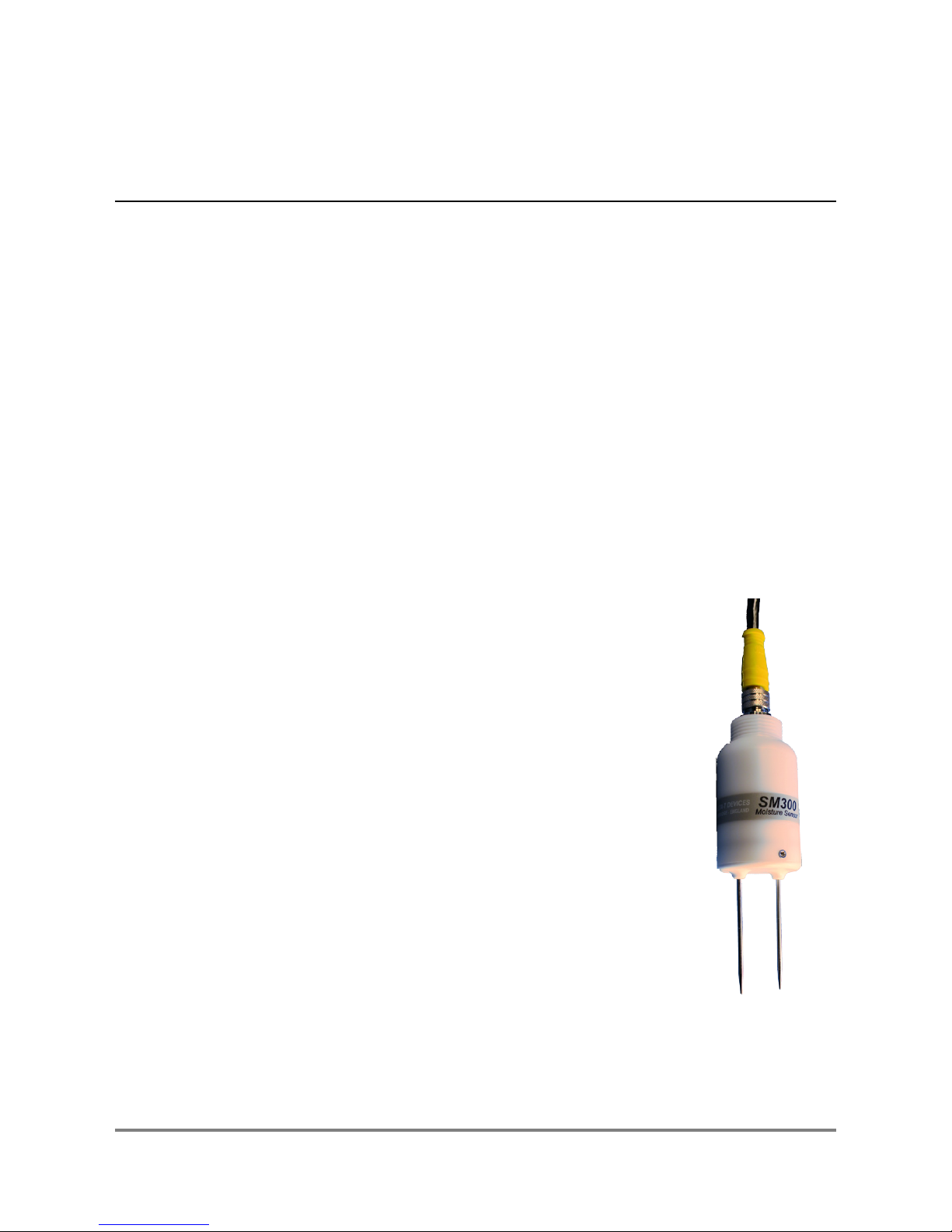
The SM300 measures soil moisture content and temperature.
Its sealed plastic body is attached to two sensing rods which
insert directly into the soil for taking readings.
A waterproof plug connects to a choice of signal cables.
Both extension cables and extension tubes can be used.
The soil moisture output signal is a differential analogue DC
voltage. This is converted to soil moisture by a data logger or
meter using the supplied general soil calibrations.
It can also be calibrated for specific soils.
Features
Soil moisture accurate to ± 2.5%
Soil temperature to ± 0.5°C over 0-40°C
Low salinity sensitivity
Excellent stability
Minimal soil disturbance
Easy installation at depth in augured holes
Waterproof connector to IP68
Rugged, weatherproof and can be buried.
Good electrical immunity
Choice of cabling system options
Cable connector, cylindrical profile and extension tube
design simplifies removal for servicing.
See also Specifications on page 29

SM300 User Manual 1.2 Introduction
6
Dimensions
67 mm
92 mm
51mm
22mm
12
40 mm
Cable connector
sealed to IP68
M12, 5 pin, male
Thread ¾inch BSP
for connecting to
Extension Tube(s)

SM300 User Manual 1.2 Introduction
7
Parts list
Your shipment may include the following:
Part Sales Code Description
SM300 SM300 sensor
with Quick Start Guide
SMSC/d-HH2
0.9m cable connects
to HH2 meter
via 25-way D-
connector
SMSC/sw-05
5m cable with
100 mm flying leads
for GP1 or DL6 logger
SMSC/lw-05
5m cable with
200mm flying leads
for DL2e logger
EXT/5W-05
EXT/5W-10
EXT/5W-25
5, 10 and 25m
extension cables.
IP68 M12 connectors
ML/EX50
ML/EX100
50 and 100cm
Extension Tube
SM-AUG-100 45mm spiral auger
1.2m long

SM300 User Manual 1.2 Introduction
8
To prevent personal injury and damage to
the probe always store and transport the
SM300 in this protective tube
CAUTION
SHARP PINS
Care and Safety
The rods of the SM300 are sharp in
order to ease insertion. Care must
be taken and handling precautions
followed.
Avoid touching the rods or exposing
them to other sources of static
damage, particularly when powered up.
Keep the SM300 in its protective tube when not in use.
Take care when attaching cables to ensure that the connectors are
clean, undamaged and properly aligned before pushing the parts
together.
Do not pull the SM300 out of the soil by its cable.
If you feel strong resistance when inserting the SM300 into soil, it is
likely you have encountered a stone. Stop pushing and re-insert at a
new location.
Do not touch the pins, particularly when the sensor is
attached to a cable. An electrostatic discharge from
your body can typically cause a temporary -10mV
offset in sensor readings for up to one hour. At worse
it may permanently damage the sensor.

SM300 User Manual 1.2 Introduction
9
How the SM300 works
When power is applied to the SM300...
...it creates a 100MHz waveform (similar to FM radio).
The waveform is applied to a pair of stainless steel rods
which transmit an electromagnetic field into the soil.
The water content of the soil surrounding the rods...
ε
...dominates its permittivity.
(A measure of a material’s response to polarisation in an
electromagnetic field. Water has a permittivity ≈81,
compared to soil ≈4 and air
≈
1)
The permittivity of the soil has a strong influence on the
applied field…
Vout …which is detected by the SM300, resulting in a stable
voltage output that…
Soil Moisture
22 %
...acts as a simple, sensitive measure of soil moisture
content.

SM300 User Manual 1.2 Operation
10
Operation
Cable Connections
Take care when attaching cables to ensure that the connectors are
clean, undamaged and properly aligned before pushing the parts
together.
Screw together firmly to ensure the connection is water-tight.
Extension cables can be joined up to a recommended maximum of
100m – see Specifications on page 29
0.9m 5m
10m
25m
5m with
100 or 200
mm bare
leads
HH2
cable
Extension
cables
Logger
cables
brown
white
blue
black
grey
green
Power 0V
Power V+
Signal HI
Signal LO
Temperature +
Cable shield

SM300 User Manual 1.2 Operation
11
Installation
Surface installation and spot measurements
Clear away any stones. Pre-form holes in
very hard soils before insertion.
Push the SM300 into the soil until the rods
are fully inserted. Ensure good soil contact.
If you feel strong resistance when inserting
the SM300, you have probably hit a stone.
Stop, and re-insert at a new location.
Note: The SM300 is not suitable for soil surface temperature
measurements. For soil temperature near the surface dig a trench and
install horizontally as shown below. Cover both SM300 and the first
30cm of cable with at least 5cm of soil.
Installing at depth
Make a 45mm diameter hole, preferably at
about 10° to the vertical using the
SM-AUG-100 auger.
Connect an extension tube e.g. ML/EX50
Push the SM300 into the soil until rods are
fully inserted. Ensure good soil contact.
Alternatively
Dig a trench, and install horizontally.

SM300 User Manual 1.2 Operation
12
Logger connections and configuration
GP1 Logger
Two SM300s can connect to each GP1.
Each soil moisture sensor is wired as a
differential, powered sensor.
These details illustrate connection to
Channels 1 and 3:
SM300 wire Colour GP1 terminal
Power 0V brown CH1 (GND)
or Temp (GND)
Power V+ white CH1 (PWR)
Signal HI blue CH1 (+)
Signal LO black CH1 (-)
Temperature + grey Temp3 (IN)
Cable shield green CH1 (GND)
Using the DeltaLINK1logger software, configure channel 1 or 2 as
sensor type SM300 and channel 3 or 4 as an SM300 Temperature
sensor.
See also GP1 Quick Start Guide and the DeltaLINK on-line Help.
1You need the PC logger software DeltaLINK version 2.4 or later. A free upgrade can
be obtained from www.delta-t.co.uk or from the Software and Manuals DVD.

SM300 User Manual 1.2 Operation
13
GP2 Logger Controller
Up to 6 SM300s can connect to a GP2.
Up to 12 can be connected if not using the temperature
sensor.
If using more than 9 you need expansion lid GP2-G5-LID.
These details illustrate connection to Channels 1 and 2:
SM300 wire Colour
GP2 terminal
Power 0V brown CH1 (PGND)
Power V+ white CH1 (PWR)
Soil Moisture Signal HI blue CH1 (+)
Soil Moisture Signal LO black CH1 (-)
Cable shield green CH1 (PGND)
Thermopile HI grey CH2(+) and CH2(-)
Fit wire link
For configuration details see the DeltaLINK2software sensor Info Panel and
Help or the GP2 User Manual.
2You need the PC logger software DeltaLINK version 3.0 or later. A free upgrade can
be obtained from www.delta-t.co.uk or from the Software and Manuals DVD.

SM300 User Manual 1.2 Operation
14
DL6 Logger
6 SM300s can be connected to a DL6.
Each soil moisture sensor is wired as a differential,
powered sensor.
A DL6 logger can only read one SM300
temperature sensor.*
These details illustrate connection to channels 6
& 7:
SM300 wiring Colour DL6
terminal
Power 0V brown 0V
Power V+ white V+
Signal HI blue IN+
Signal LO black IN-
Temperature + grey
RES IN+
Cable shield green
In DeltaLINK3configure channel 6 as type SM300 and channel 7 as a
type SM300 Temperature sensor.
See also the DL6 Quick Start Guide and the DeltaLINK online Help.
3You need the PC logger software DeltaLINK version 2.4 or later. A free upgrade can
be obtained from www.delta-t.co.uk or from the Software and manuals DVD.

SM300 User Manual 1.2 Operation
15
DL2e Logger
Up to 60 SM300s can be connected to a DL2e
logger (if not using the temperature sensor
channel).
Up to 30 SM300s can be connected if also
reading the temperature sensor.
Each moisture sensor is connected as a differential, powered sensor.
These details illustrate connection to Channels 57 and 58 using a
LAC1 input card configured in 15-channel mode, and warm-up channel
63:
SM300 wiring Colour DL2e terminal
Power 0V brown CH62- or 61-
Power V+ white CH63 NO
Signal HI blue CH58+
Signal LO black CH58-
Temperature + grey CH57+ and CH57-
Cable shield green CH61- or 62-
Configure the chosen DL2e logger channels by selecting the
appropriate S3M and S3O sensor types for mineral and organic soils
and S3T for the temperature sensor type listed in the Ls2Win4sensor
library.
See the DL2e User Manual and the Ls2Win online help
4You need a PC running Ls2Win version 1.0 SR6 or later. A free upgrade can be
obtained from www.delta-t.co.uk or from the Software and manuals DVD.

SM300 User Manual 1.2 Operation
16
Other data loggers
The SM300 soil moisture output should be connected as a differential,
powered sensor.
Configure the logger to convert the SM300 readings from milliVolts into
soil moisture units by using either :-
Polynomial conversion on page 25 or
Linearisation table conversion on page 26
Note: Output signals in the range 0 to 1.0 volts from the SM300,
corresponding to ~0 to 60% water content in mineral soils – see
Linearisation table conversion on page 26.
Note: The SM300 has been optimised for warm-up of 0.5 to 1 second
duration.
It is recommended that the sensor is not powered continuously.
The temperature sensor output should be read as a resistance and the
logger configured with a look-up table to covert the measured resistance
to temperature.
See SM300 Temperature Measurement on page 47
and Resistance to Temperature Lookup Table on page 50.
Logging Advice
Allow 20mins for the temperature readings to stabilise after installation
Do not log faster than 1 minute to avoid SM300 self-heating, which
could affect the accuracy of temperature readings.

SM300 User Manual 1.2 Operation
17
Logger Grounding
Sub-optimal grounding of a DC power supply and its cabling
to a logger can cause currents in the screen of the cable
connected to a soil moisture sensor, and so cause corrosion
at the M12 connector of an SM300 soil moisture sensor. In
addition, if used in an electrically noisy environment - such as
a farm or greenhouse - then the presence of a ground loop
can permit AC signals to inject noise and so disrupt readings.
To minimise sensor cable-screen currents that can result
from the DC power supply unit and its cabling to the logger,
earth the logger using a 1m long copper-clad earth stake.
Figure
1Showing the use of a 1m long copper-clad earthing rod connected to
logger earth

SM300 User Manual 1.2 Operation
18
Ungrounded system
In the example shown in Figure 2 both the logger and the power
supply are not grounded, so a current loop can exist between the
sensor and the mains power source, allowing noise to be injected
into readings, and also galvanic corrosion to the M12 connector on
the SM300.
Figure 2This diagrams shows that if the logger is not well grounded then a
potential ground loop can exist between the sensor and the power supply and/or
mains power, and also the risk of galvanic corrosion to buried M12 connectors on
the SM300 and cable.

SM300 User Manual 1.2 Operation
19
Fully grounded system
Figure 3This diagram shows the logger, power supply and sensor all grounded.
This minimises the possibility of galvanic corrosion of the SM300 connector. It also
minimises the possibility of nearby AC-powered machinery injecting noise into the
readings. The potential ground loop between logger and sensor is mitigated by the
differential wiring of the SM300
Logger grounded
Figure 4This diagram shows a battery or high quality power supply with no
leakage current to ground. The logger is grounded. The potential ground loop
between logger and sensor is mitigated by the differential wiring of the SM300.
This is the best arrangement.

SM300 User Manual 1.2 Operation
20
Device: SM300
Soil Type:
Mineral
HH2 Meter
This assumes you have version 2.5 or later for both the PC
software HH2Read and the HH2 firmware (see foot of page).
Connect the SM300 to the HH2 meter.
Press Esc to turn the meter on, and if necessary press
again until the HH2 displays the start-up screen.
Set the meter to read from an SM300:
►Press Set and scroll down to the Device option.
►Press Set again and scroll down to select
SM300.
►Press Set to confirm this choice.
Make sure the HH2 is correctly configured for your soil type:
►At the start-up screen, press Set and scroll down to the Soil Type option.
►Press Set again and scroll down to the
appropriate soil type (use Mineral for sand,
silt or clay soils or Organic for peaty soils)
►Press Set to confirm this choice.
Choose the units you want for displaying readings.
►At the start-up screen, press Set and scroll down to the Display option.
►Press Set again and scroll down to select units.
►Press Set to confirm this choice.
Press Read to take a reading.
Press Store to save or Esc to discard the reading.
Remove the SM300 from the soil and move to a new location...
If you have saved data, connect your HH2 to a PC and run
HH2Read to retrieve the readings.
See also: Support for the SM300 Soil Moisture Sensor with an HH2
and HH2 User Manual and HH2 User Manual Addendum to V4 - SM300.
Note: the HH2 does not display or store SM300 temperature readings.
Note: For an upgrade, contact Delta-T.
SM300 Store?
20.3%vol
Table of contents
Other Delta-T Devices Accessories manuals