Delta-T Devices WET150 User manual
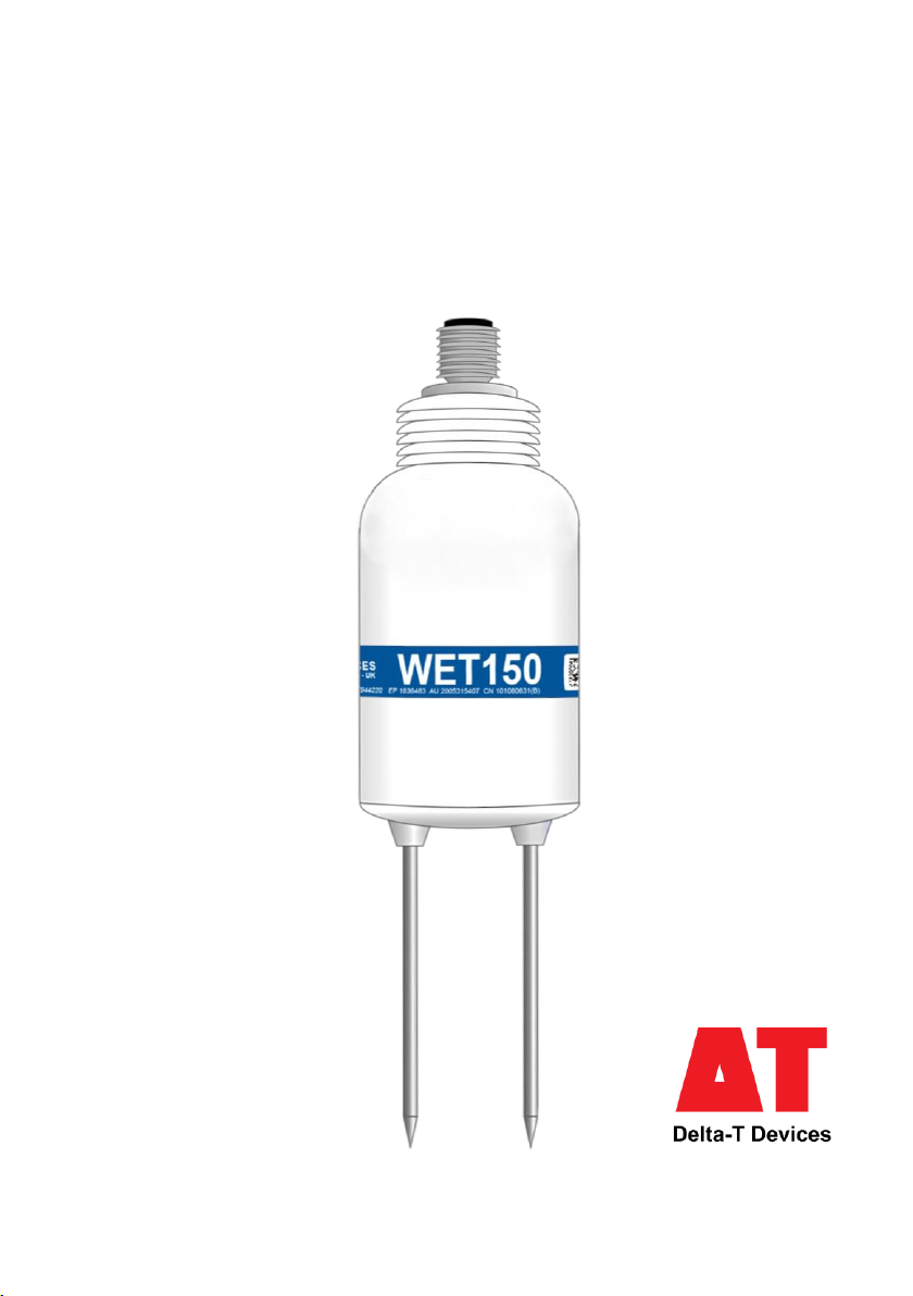
WET150 sensor
Quick Start Guide
Version 3.0

© 2022, Delta-T Devices Ltd Page 2
Getting started
Thank you for purchasing the WET150, Delta-T’s robust and accurate sensor for water
content, electrical conductivity and temperature. To ensure you get the most out of
your sensor, we recommend the following steps:
a) Check you have all the equipment you need
For a list of accessories and additional equipment see section “System parts”
(page 3).
b) Check how to connect your sensor
See section “Connecting your WET150” on page 4.
c) Check your sensor is properly configured for your intended use
The WET150 is highly customisable to ensure maximum effectiveness in a
wide variety of applications. See section “Configuring your WET150 for use”
on page 5.
d) Check the sensor can be correctly installed
See section “Installation” (page 6).
e) Review the care and maintenance requirements of your sensor
See section “Care and Maintenance” (page 6).
Features of the WET150
© 2022, Delta-T Devices Ltd Page 3
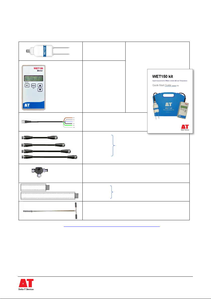
System Parts
*Available online via: https://delta-t.co.uk/product/wet150/#support
WET150
sensor
Note: the WET150 and
Meter are sold together as
the WET150 kit with a
dedicated Quick Start
Guide*
WET150 Meter
SMSC/lw-05m 5m cable
with 200mm flying leads
EXT/5w-01
EXT/5w-05
EXT/5w-10
EXT/5w-25
GP2-STP1sensor Network T-piece
ML/EX50
ML/EX100
SM-AUG-100 45mm spiral auger
extension tubes
1, 5, 10 and 25m
extension cables
© 2022, Delta-T Devices Ltd Page 4
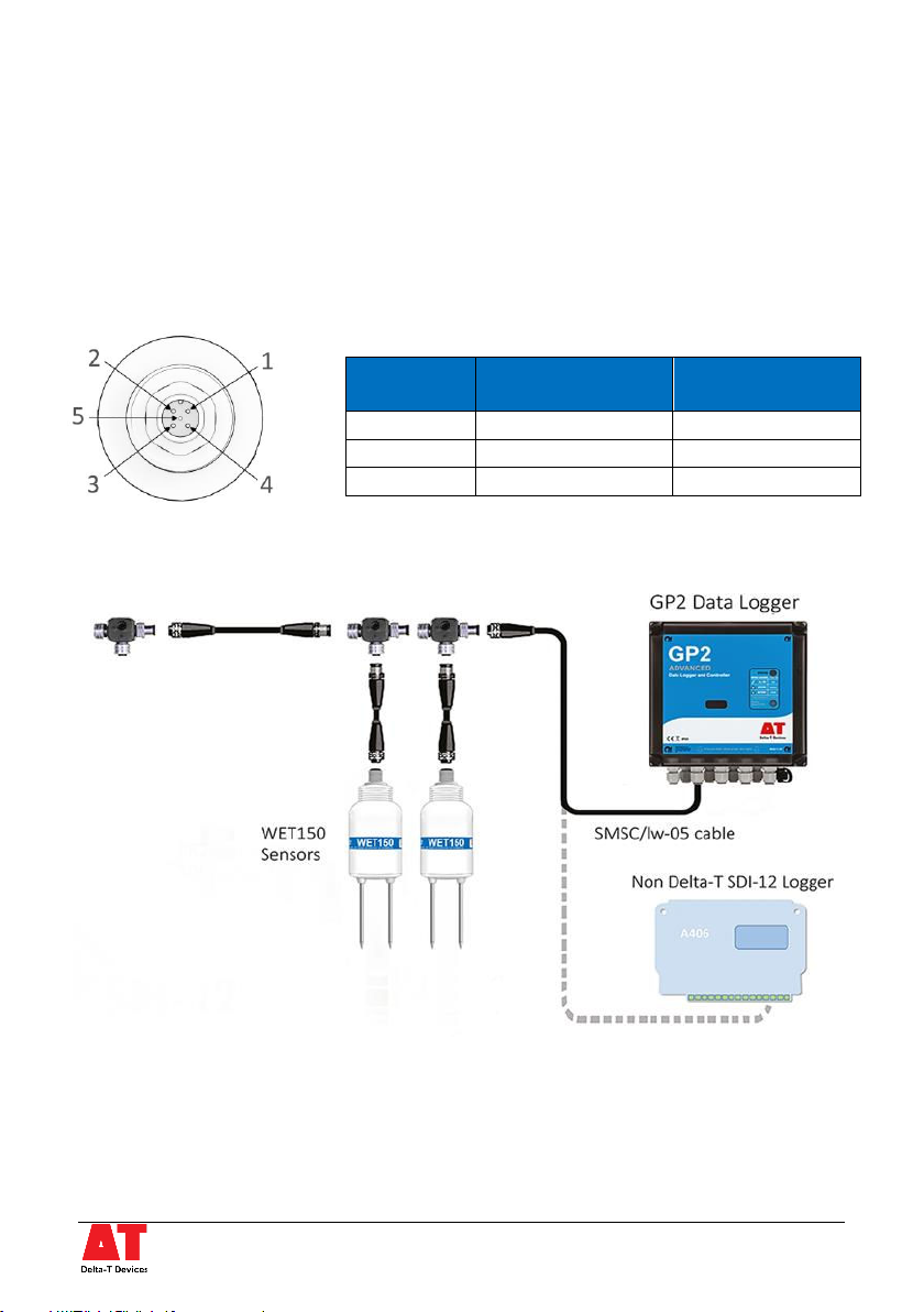
Connecting your WET150
The WET150 complies with v1.3 of the SDI-12 Standard, published by the SDI-12
Support Group. As such it is compatible with a wide range of equipment. For details of
how to connect it to your specific equipment, refer to your equipment’s instructions
on installing SDI-12 sensors.
Connections
IMPORTANT: before connecting the sensor to a network, the address must be set on
the sensor. See section “Configuring your WET150 for use”
Cables can be joined via extension cables and T-connectors. Maximum cable lengths
depend on configuration details. As an example, 200m with 10 WET150s each
connected via a 5m extension cable works reliably with the GP2 Data Logger.
WET150
pin
SMSC/lw-05m wire
colour
Function
2
White
Power
3
Blue
Ground
4
Black
Data
© 2022, Delta-T Devices Ltd Page 5
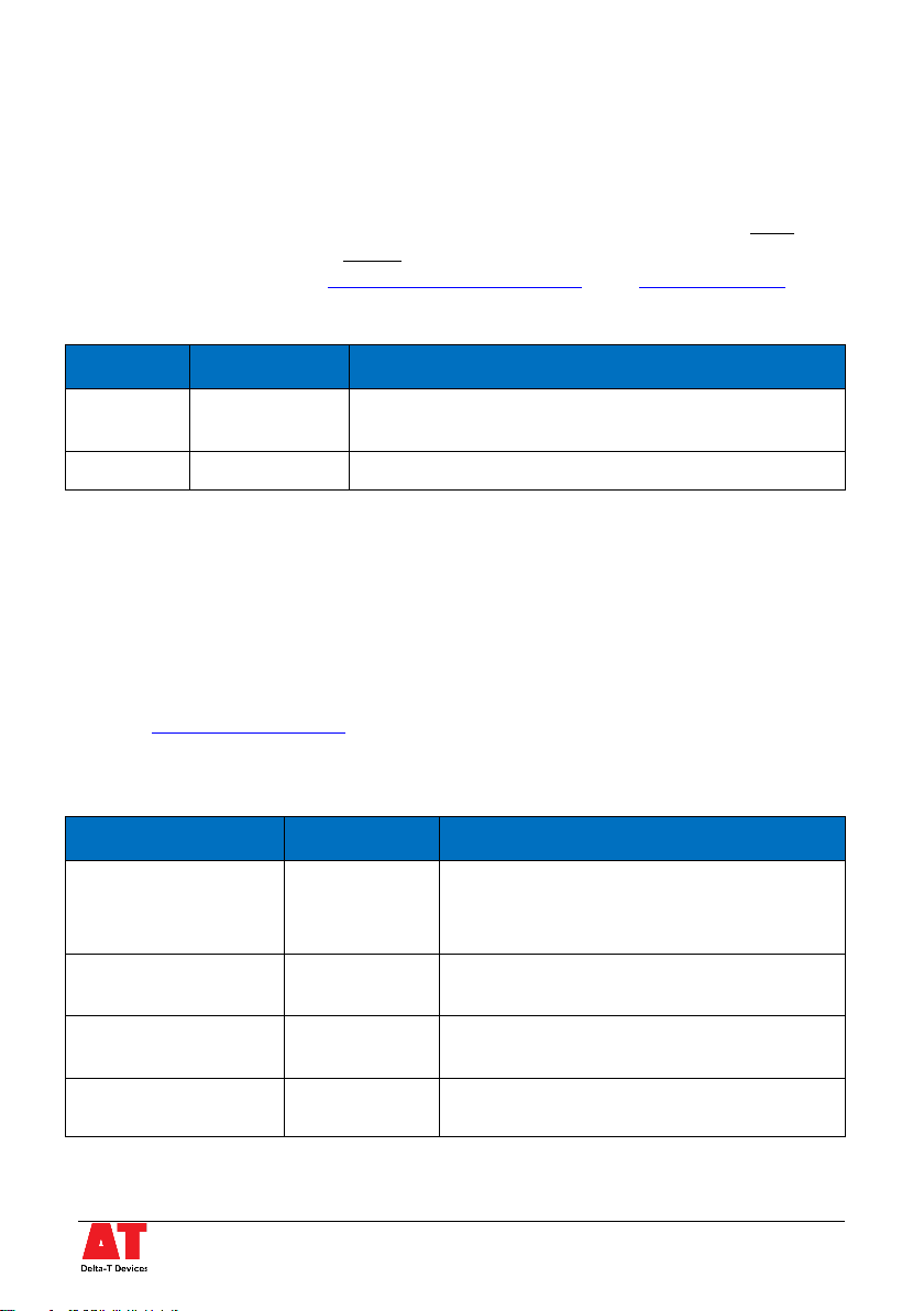
Configuring your WET150 for use
SDI-12 addresses (do this before network installation)
WET150s are supplied with the default address “0”, but each SDI-12 sensor must be
re-assigned a unique address before connecting it to a network –see instructions on
how to set addresses in the SDI-12 for GP2 User Manual or the WET150 Kit QSG.
SDI12 commands used:
Command
Sensor reply
Notes
?!
0
The sensor responds with its address (0 in this example).
Cannot be used if more than one sensor is connected.
0Aa!
a
Changes the address of sensor from 0to a
Settings for ECp and water content measurement
For pore water conductivity (ECp) and water content measurements, the WET150
contains user-configurable parameters. By default, the WET150 is shipped with
generic parameters that match the generic parameters in Delta-T’s WET2 sensor. We
strongly recommend you review these settings. Best results will be obtained with
parameters customised to your specific medium; Delta-T also supplies a list of generic
parameters which give good performance for several common soils and substrates.
See the WET150 User Manual for more details.
For example, here is the SDI-12 command sequence to modify the “mineral soil” ECp
soil parameter:
Command
Sensor reply
Notes
aXU1D?!
a -8.9
Command queries what the current ECp soil
parameter is for measurement set M1
(“Mineral soil”); the sensor replies it is -8.9
aXU1B=Z!
a OK
Command tells the sensor that measurement
set M1 is to be configurable.
aXU1D=2.72!
a 2.72
Command then sets the ECp soil parameter for
measurement set M1 to 2.72
aM1!
a<values>
Command requests a measurement using M1
(now using the custom soil parameter).
Settings configuration can be done before or after connection to the network.
© 2022, Delta-T Devices Ltd Page 6
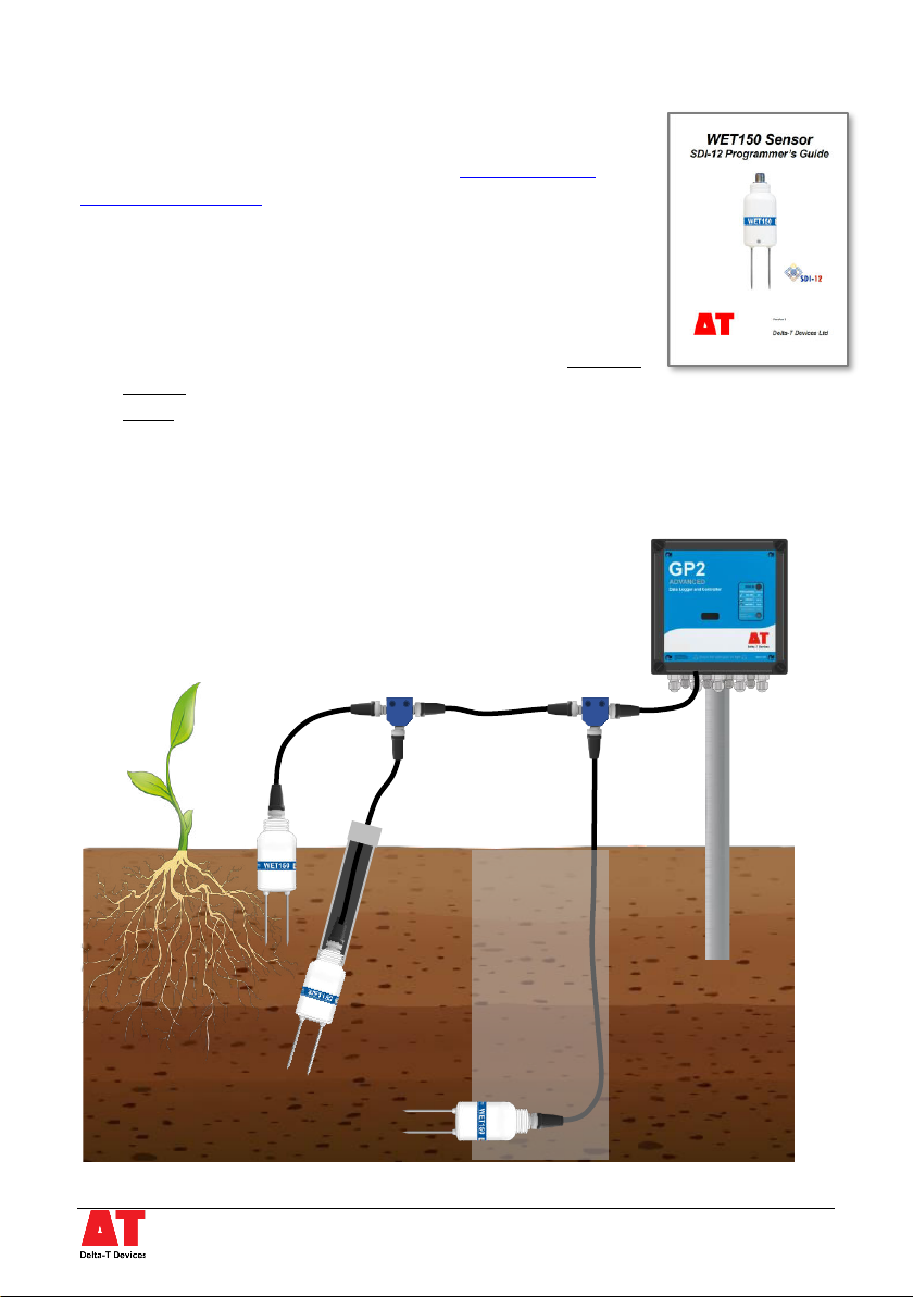
More SDI-12 commands
The WET150 supports a comprehensive set of SDI-12
commands for configuring the sensor. The WET150 SDI-12
Programmer’s Guide contains full details.
Care and maintenance
◼Do not touch the WET150 rods or expose them to other
sources of static damage, particularly when powered up.
◼Ensure that connectors are clean, undamaged and properly
aligned before pushing the parts together. Screw together
firmly for a water-tight seal. We do not recommend tightening with a spanner or
other tool as this can lead to overtightening and damaging the o-ring seal.
◼Do not pull the sensor out of the soil by its cable.
Installation
© 2022, Delta-T Devices Ltd Page 7
Surface installation and spot measurements
Consistent technique is critical for repeatable results. Varying how hard the sensor is
inserted can alter the bulk density of the soil/substrate and cause readings to diverge.
1. Clear away any stones. Pre-form holes in very hard soils before insertion.
2. Push the WET150 into the soil, fully inserting the rods.
3. If you feel strong resistance when inserting the WET150, you have probably
hit a stone. Stop, and re-insert at a new location.
Note: Partial or full burial of the WET150 will improve temperature accuracy, and
reduce effects of air temperature and radiant heat.
Installing at depth
1. Auger a 45mm diameter hole, using the SM-AUG-100 (see “System Parts”
section). ~10° to vertical is recommended.
2. Fit an extension tube to the WET150 –remember to fit the connector and
pass the cable through the extension tube first.
3. Push the WET150 into the soil, fully inserting the rods.
Alternatively
•Dig a trench and install horizontally into the wall of the trench.
•Backfill carefully to avoid disturbing the sensor
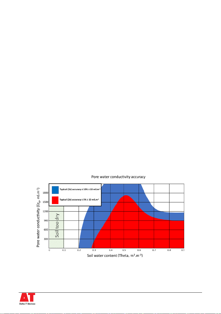
Pore Water EC (ECp) accuracy
The following graph indicates the range of pore water conductivity (ECp) that can be
most accurately measured by the WET150 at different soil moisture levels:
Notes:
[1] The WET150 has been carefully optimised to provide accurate readings in soils and substrates - readings taken in water or air may not
meet the full specification.
[2] The ECp contour map is based on measurements from 30 sensors at 20°C in NPL* traceable media. Calculated ECp readings are derived
from the Hilhorst equation, using the generalised “mineral” soil calibration and the default soil parameter = 4.1
* NPL is the UK's National Metrology Institute, developing and maintaining the national primary measurement standards.

© 2021, Delta-T Devices Ltd Page 8
Outline specifications
Please refer to the WET150 User Manual and
WET150 SDI-12 Programmer’s Guide for further
details and important notes.
Volumetric Water Content
Accuracy
± 3% (with a calibration matching the soil / substrate)
Range
Accurate range: 5 to 100%vol, ECb0 to 500mS.m-1
Full range: 0 to 100%vol
Permittivity (ε’)
Accuracy
± (3% of reading + 0.8 ε’) 1 →40 for ECp ≤ 800mS.m-1
± 5% of reading 40 →80 for ECp ≤ 500mS.m-1
Range
Accurate range: 1 to 80, full range: 1 to 90
ECb (bulk conductivity)
Accuracy
± (6% + 10mS.m-1)
Range
Accurate range: 0 to 1200mS.m-1
Full range: 0 to 2000mS.m-1
Temperature (the WET150 must be buried to accurately measure soil temperature)
Accuracy
± 0.5 °C
± 0.7 °C
Range
Accurate range:
0 to +40 °C
Full range:
-20 to +60 °C
Operating specifications
Power requirement
6 to 20V, ~22mA x 12ms (with short 45mA peak)
Maximum cable length
>100m (see User Manual for tested configurations)
Interface
SDI-12 version 1.3
Operating range
-20 to +60°C
Environmental
IP68
Sample volume
55 x 70 mm diameter
Dimensions, weight
143 x 40 mm diameter, 77g
tel: +44 (0) 1638 742922
website: www.delta-
t.co.uk
UK Headquarters:
130 Low Road,
Burwell,
Cambridge,
CB25 0EJ, UK
EU Regulatory Enquiries:
Delta-T Devices Europe,
Ground Floor, 71 Lower
Baggot Street, Dublin 2,
D02 P593, Ireland
Doc No.: WET150-QG-01-3
Other manuals for WET150
3
Table of contents
Other Delta-T Devices Accessories manuals


