Delta-T Devices WET150 User manual

WET150 sensor
Water content, ECand Temperature sensor for irrigation monitoring
QuickStartGuide version1.1

© 2021, Delta-T Devices Ltd Page 2
The WET150
Cables
Extension cables
To GP2 and other
loggers
Connector
Fully waterproof
M12 connector
Installation
Threads enable
extension rods to be
screwed on for easy
insertion in augered
holes, minimising soil
disturbance
Detectors
Soil moisture content
and EC are detected by
sensitive circuits
operating at 100MHz
Sensing field
Extends ~100mm into
the soil, but field is
strongest close to the
rods - install carefully
to avoid air gaps
SDI-12
Industry-standard digital
interface, compliant to
version 1.3
Outputs
Sophisticated correction
algorithms ensure
accurate readings across
the full range of water
content, EC and
temperatures
Temperature
Thermistor is located
within the base –
equilibrates to the soil
temperature when
installed, less well for
portable
measurements

© 2021, Delta-T Devices Ltd Page 3
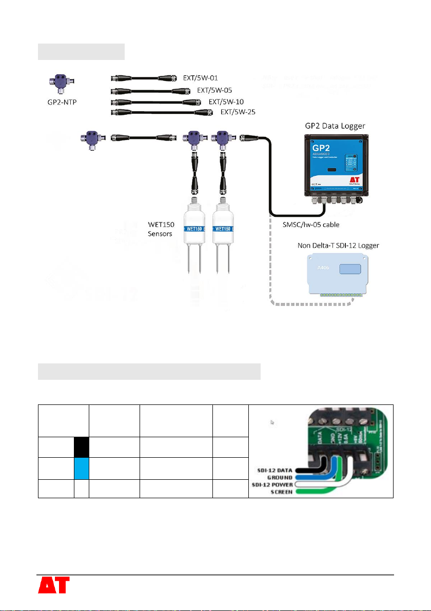
System parts (not to scale)
Care and maintenance
◼Do not touch the WET150 rods or expose them to other
sources of static damage, particularly when powered up.
◼Ensure that connectors are clean, undamaged and
properly aligned before pushing the parts together.
Screw together firmly for a water-tight seal.
◼Do not pull the sensor out of the soil by its cable.
◼If you feel strong resistance when inserting into soil, it is likely you have
encountered a stone - stop pushing and re-insert at a new location.
WET150 sensor
Note: the WET150 and
Meter are sold together as
the WET150 kit with a
dedicated Quick Start
Guide
WET150 Meter
SMSC/lw-05m 5m cable with 200mm flying
leads
EXT/5w-01
EXT/5w-05
EXT/5w-10
EXT/5w-25
GP2-NTP T-connector
ML/EX50
ML/EX100
SM-AUG-100 45mm spiral auger
extension tubes
1, 5, 10 and 25m extension cables
© 2021, Delta-T Devices Ltd Page 4
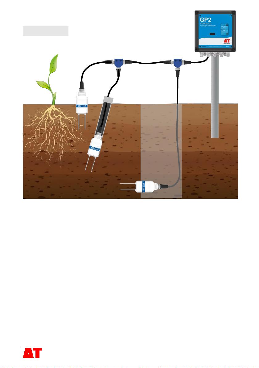
Installation
Surface installation and spot measurements
◼Clear away any stones. Pre-form holes in very hard soils before insertion.
◼Push the WET150 into the soil, fully inserting the rods to ensure good soil contact.
◼If you feel strong resistance when inserting the WET150, you have probably hit a
stone. Stop, and re-insert at a new location.
Note: With surface installation, air temperature and radiant heat on the sensor body
can affect temperature readings. Partial or full burial of the WET150 will improve
temperature accuracy, particularly where there is a large temperature difference
between the air and the soil or substrate.
Installing at depth
◼Auger a 45mm diameter hole, ~10° to vertical is recommended.
◼Fit an extension tube to the WET150 –remember to fit the connector and pass the
cable through the extension tube first.
◼Push the WET150 into the soil, fully inserting the rods to ensure good soil contact.
Alternatively
◼Dig a trench, and install horizontally into the wall of the trench.
© 2021, Delta-T Devices Ltd Page 5
Connections
Cables can be joined via extension cables and T-connectors. Maximum cable lengths
depend on configuration details. As an example, 200m with 10 WET150s each
connected via a 5m extension cable works reliably with the GP2 Data Logger.
Connection to a GP2 data logger
Using logger power
Wiring diagram for connecting a WET150 (or SDI-12 network) to the SDI-12 channel in
the GP2 using the SMSC/lw-05 cable and the logger’s internal +12V Power channel.
Note: the grey and brown wires are not connected and can be trimmed off.
Set DeltaLINK program’s Measurement, Power channel to +12V.
Power is only applied to the SDI-12 cable when required by a sensor.
Wire
colour
GP2
terminal
M12
plug
pins
Black
DATA
SDI-12 Data
4
Blue
GND
Sensor ground
/ power return
3
White
12V
Sensor power
2

© 2021, Delta-T Devices Ltd Page 6
Using external power
Wiring diagram for connecting a WET150
(or SDI-12 network) to the SDI-12 channel
of a GP2 logger using an external
permanent power supply or battery
connection (which should be appropriately
fused).
Here the SDI-12 power is permanently on. If you only
want the external power switched on when needed then
feed the 12V (white) cable through one of the GP2 relays
and select the relay, e.g. RLY1, for the DeltaLINK
program’s Measurement, Power channel
See also SDI-12 for GP2 User Manual.
GP2 configuration
You need a PC running DeltaLINK version 3.9 or later and connected to the GP2. For
help on this see DeltaLINK Help “How to Connect to the logger”
1. Connect the WET150 directly to the GP2 with the supplied cable.
2. Start DeltaLINK:
◼Click on Program and select Change.
◼Right click on Channel 1 and select WET150 from the drop-down menu.
◼To change the default settings, double click on an Input channel to open
Input Channel Properties, where you can change the Units, Soil type and
Data storage settings.
◼Set the Recording Interval in the Program window...
… there are many other options - refer to the GP2 user manual for details.
◼When finished, click on Apply to install the program in the logger.
3. To check the connections, select the Sensors tab and click on Read now to see
the WET150 readings.
4. When ready, select the Logger window and
click on Start to start logging…
5. …later to collect the data, connect to the GP2
and select the Dataset window from which you
can retrieve and display all stored readings.

© 2021, Delta-T Devices Ltd Page 7
SDI-12 commands
The WET150 supports a full set of SDI-12 commands for configuring the sensor and
its outputs and for taking readings. The full set can be found in the online WET150
User Manual (SDI-12 supplement), the following table lists just the 4 basic commands:
Command
Sensor response
Notes
?!
a<CR><LF>
The connected sensor responds with its
address (ain this example). Cannot be used
if more than one sensor is connected.
aAb!
b<CR><LF>
Changes the address of sensor afrom ato b
aM!
atttn<CR><LF>
Sensor abegins a measurement and
responds with the time in seconds until the
measurement will be ready (ttt) and the
number of values to be returned (n).
aD0!
a<values><CR><LF>
Sensor areturns 3 default values:
•Permittivity** (εʹ)
•Pore water conductivity (ECp, mS.m-1)
compensated to 25°C at 2%/°C.
•Soil temperature (°C)
** Permittivity is an electrical property of soils and substrates that is largely determined
by water content and is measured by the WET150. See the online WET150 User
Manual for details on how permittivity is used to calculate water content.

© 2021, Delta-T Devices Ltd Page 8
Specifications
Please refer to the online WET150 User
Manual for full specification and further
details:
Volumetric Water Content
Accuracy
± 3% (with a calibration matching the soil / substrate)
Range
Accurate range: 5 to 100%vol, ECb0 to 500mS.m-1
Full range: 0 to 100%vol
ECb(bulk conductivity)
Accuracy
± (6% + 10mS.m-1)
Range
Accurate range: 0 to 1200mS.m-1
Full range: 0 to 2000mS.m-1
Temperature (WET150 must be fully buried to accurately measure soil temperature)
Accuracy
± 1°C
Range
Accurate range: -20 to +50°C
Full range: -20 to +60°C
Operating specifications
Interface
SDI-12 version 1.3
Maximum cable
length
>100m (see User Manual for tested configurations)
Power requirement
6 to 20V, ~22mA over 12ms (includes short 45mA peak)
Operating range
-20 to +60°C (sensor does not detect ice)
Environmental
IP68
Sample volume
55 x 70 mm diameter
Dimensions
143 x 40 mm diameter
Weight
77g
Delta-T Devices Ltd
130 Low Road, Burwell, Cambridge CB25 0EJ, UK
Tel: +44 (0) 1638 742922
WET150 Quick Start Guide version 1.1
Other manuals for WET150
3
Table of contents
Other Delta-T Devices Accessories manuals


Popular Accessories manuals by other brands

QOLSYS
QOLSYS IQ GLASS Quick install guide

Becker
Becker Centronic SensorControl SC711 Assembly and operating instructions

Paraavis
Paraavis SPIRIT manual

Palram
Palram Canopia Nancy 4500 How to assemble

Guzzanti
Guzzanti GZ-0824 instruction manual

Physik Instrumente
Physik Instrumente E-509 Series user manual


