manuals.online logo
Brands
  1. Home
  2. •
  3. Brands
  4. •
  5. Salus
  6. •
  7. Controllers
  8. •
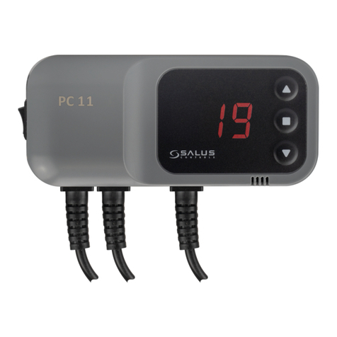
  9. Salus PC11W User manual

Salus PC11W User manual

Model PC11W
PL Sterownik do pompy C.O. lub pompy C.W.U.
ENG Pump controller for heating or hot water
RUS      
 
RO Controler pentru pompa de recirculare sau pompa
de apa calda
PL
SALUS PC11W

          

 (O) 
(U ).

antystop
sezonem grzewczym. Polega ona na cyk

     alarm    
           
zamontowany czujnik p
system antyzamrożeniowy
           



                
      C      
 sekundach sterownik sam przejdzie w tryb pracy


               
           U    


           
 .

Histereza
           
-
             

Funkcje sterownika
U- temperatura wyłączenia pompy powyżej ustawionej temperatury
O- temperatura włączenia pompy powyżej ustawionej temperatury

uprawnienia elektryczne!
Czujnik 
 zanurzony w

Przewód zasilający 
- 230V,
-zielony (ochronny) - 
UWAGA: Pojawienie się na wyświetlaczu komunikatu „99” oznacza awarię czujnika
temperatury.
ENG
SALUS PC11W
Operating principle
The controller can be used as heating system pump control or hot water pump control. By this
controller we can set two temperature: turning ON (O) or turning OFF (U).
The pump will turn ON if temperature will be higher than set temperature (O).
The pump will turn OFF if temperature will be higher then set temperature (U).
Security features
The thermostat is equipped with a system to prevent pump sticking:
anti stop function - about every 15 days the pump is activated for 15 sec.
frost protection function - after a decrease temperature in the system   C
pump  C .
Another useful feature is alarm sound function which signals too high temperature
level. It shall be started when the temperature at the point where the sensor is
mounted exceeds 90 
Operation
Set temperature by pressing ( enter the options menu), the display should appear as a
flashing letter C, when you can change the desired temperature by buttons . After a few
seconds the thermostat will go in to normal mode and will display current temperature of the
system.
OFF Temperature by pressing and hold ( enter the options menu) until the display shows a
flashing letter U. At this moment you can change the desired temperature by means buttons .
Manual Mode
In this function you can check whether the pump is connected in order, by simultaneously
pressing the buttons .
Next one pressing the buttons will turns off the pump.
Hysteresis
This is a difference between the temperature cycle entry and the temperature thermostat
switching back to standby. The thermostat has a fixed 2-stage hysteresis. For example, after
setting the temperature at , pump will take place after crossing the  will
be off when the temperature falls to 48 C
Function thermostat
U - pump switch OFF over set temperature
O –pump switching ON over the set temperature
Mounting
Installation should be made by a person with adequate electrical power!. The sensor
should be placed at the exit of the boiler using the clamp and isolated from external factors by
using duct tape (can not be immersed in any liquid). The power cord should be connected to the
pump as follows:
blue and brown - 230V,
yellow /green (protective) should be connected to ground.
NOTE: If you see “99” on the LCD display – temperature sensor is broken.
RUS
SALUS PC11W

        

        (О),
 (U).

антистоп


      
      
        
C.
   системой предупреждающей замерзание 




 

  


 

U.  .


 


-



U –температура выключения термостата
O –нижний порог включения термостата

разрешениями на
работу с электроприборами!
Датчик 


Провод, питающий 
 - 230V,
- 
Если вы видите "99" на ЖК-дисплее - датчик температуры не работает
RO
SALUS PC11W
Principii de funcionare
Termostatul PC11W poate fi folosit pentru comanda pompei de recirculare sau a pompei
de pardoseala. Pump Poate fi programat sa porneasca pompa in momentul in care se
depaseste temperatura setata (O) , sau sa o opreasca in momentul in care se depaseste
temperatura setata (U).
Caracteristici suplimentare
Termostatul este echipat cu sisteme ce previne blocarea pompei:
functia anti-stop la fiecare 15 zile, termostatul comanda pornirea pompei timp de 15
sec.
functia antiinghet      controlerul
porneste functionarea permanenta a pompei.
Operarea controlerului
 
pictograma C va semnaliza intermitent, dupa care prin apasarea butoanelor puteri aduce
modificari temperaturii setate. Dupa cateva secunde termostatul va reveni la modul normal de
lucru.
Operare manuala
Pentru functionarea continuua a pompe apasati simultan butoanele . Pentru a dezactiva
aceasta functie executati aceeasi operatiune.
Histereza (diferenta la pornire)
Acesta este diferenta dintre temperatura la care termostatul porneste pompa si temeratura la
care aceasta o opreste.
Termostatul are o histereza fixa. De exemplu, daca temperatura setata   
porni cand temperatura detectata de senzor va depasi temperatura setata, si se va opri cand

Functile termostatului
U –termostatul oprește pompa la temperatura setată
O –termostatul pornește pompa la temperatura setată
Alarma
Controlerul este echipa cu o alarma auditiva pentru a instiinta cand temperatura detectata de

Montarea controlerului
Montarea controlerului trebuie facuta de catre o persoana autorizata! Senzorul trebuie montat la
iesirea din boiler cu ajutorul clemei de prindere si izolata de factori exteriori cu ajutorul bandei
izolatoare (senzorul nu este imersibil in lichide).
Cablul de alimentare al pompei trebuie conectat astfel:
albastru si maro 230 V
galben-verde - impamantare
Dacă vedeți "99" pe ecranul LCD - senzor de temperatură este rupt
SCHEMATY PODŁĄCZEŃ/ WIRING DIAGRAMS
PRZYCISKI / BUTTONS
GWARANCJA
1.              

2.             

3. 
a) 
b) 
c) 
d) 

a) Uszkod
b)  
c) 
4.  


1.

6.

Power supply indicator
Sound alarm


Indicator termostat pornit

2.

7.

Indicator pump operation
Display




3.
Klawisz plus
8.
Czujnik
Plus key
Sensor


Buton +
Senzor
4.
Klawisz menu
9.
Zasilanie pompy
Menu key
Power supply pump


Buton meniu

5.
Klawisz minus
10.
Zasilanie 230V
Minus key
Power supply 230V


Buton -
Alimentare termostat - 230V
CALOR SRL
Str. Progresului nr. 30-40, sector 5, Bucuresti
tel: 021.411.44.44, fax: 021.411.36.14
www.calorserv.ro - www.calor.ro

Other Salus Controllers manuals

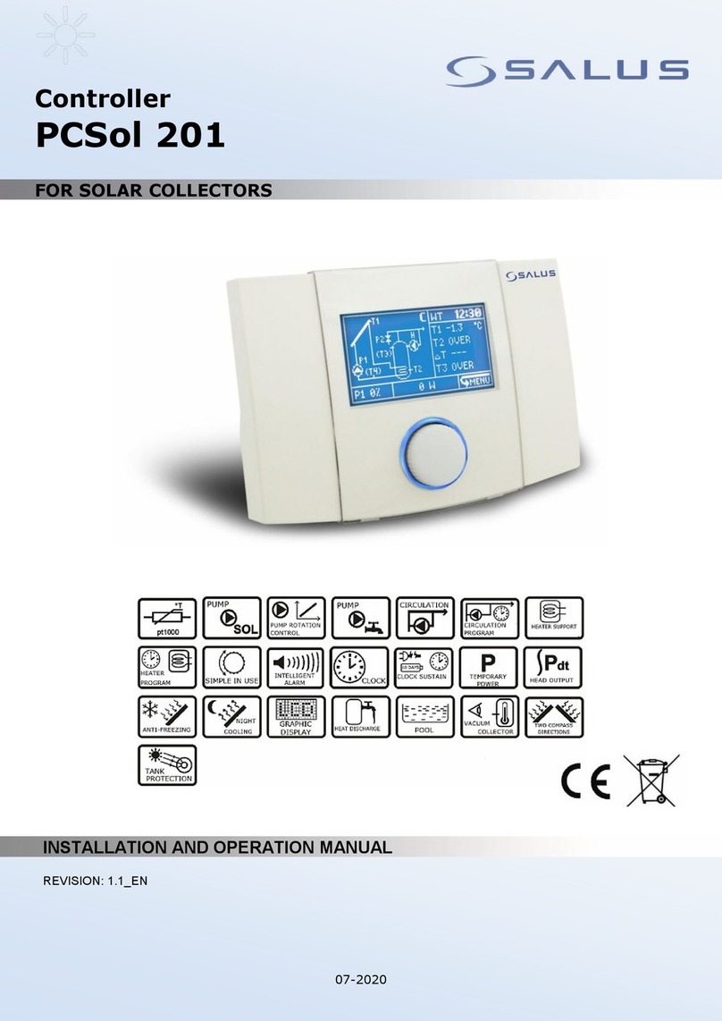
Salus PCSol 201 User manual

Salus

Salus PCSol 201 User manual

Salus SP220 User manual

Salus

Salus SP220 User manual

Salus TRV10RFM User manual

Salus

Salus TRV10RFM User manual

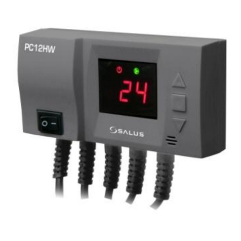
Salus PC12HW User manual

Salus

Salus PC12HW User manual

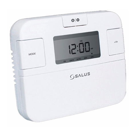
Salus EP310 User manual

Salus

Salus EP310 User manual

Salus WT100 Specification sheet

Salus

Salus WT100 Specification sheet

Salus RX10RF User manual

Salus

Salus RX10RF User manual

Salus EP110 User manual

Salus

Salus EP110 User manual

Salus PC11W User manual

Salus

Salus PC11W User manual

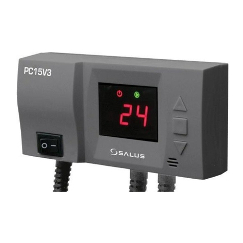
Salus PC15V3 User manual

Salus

Salus PC15V3 User manual

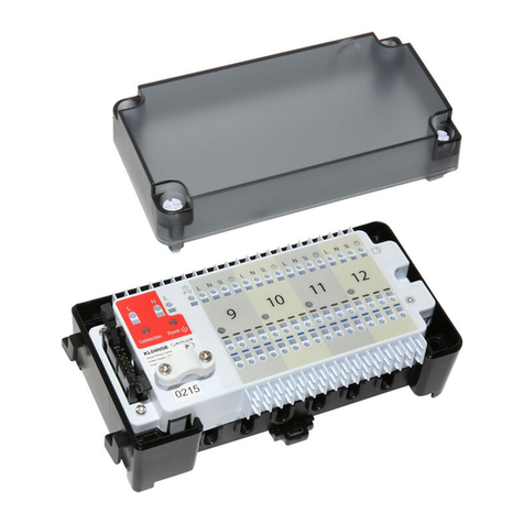
Salus KL04NSB User manual

Salus

Salus KL04NSB User manual

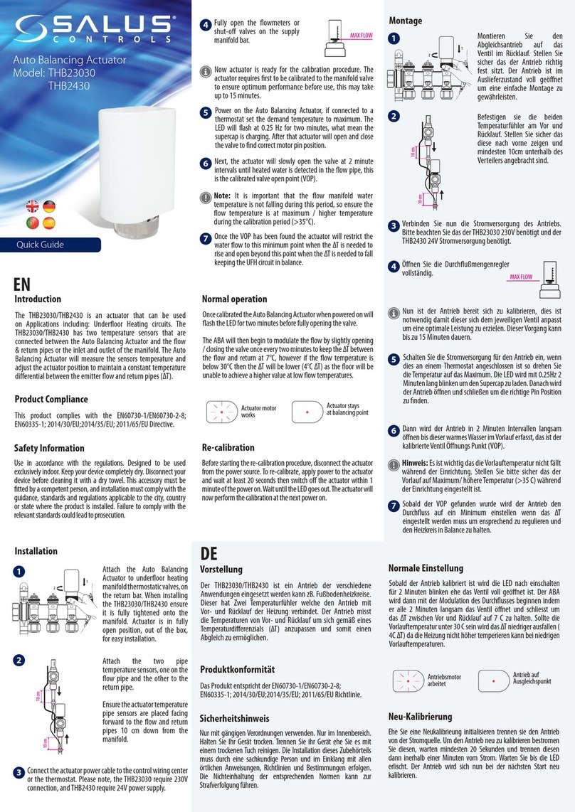
Salus THB23030 User manual

Salus

Salus THB23030 User manual

Salus AKL06P User manual

Salus

Salus AKL06P User manual

Salus PC16F User manual

Salus

Salus PC16F User manual

Salus EP210 User manual

Salus

Salus EP210 User manual

Salus TRV10RFM User manual

Salus

Salus TRV10RFM User manual

Salus PCSol 150 User manual

Salus

Salus PCSol 150 User manual

Salus PCSol 300 User manual

Salus

Salus PCSol 300 User manual

Salus TRV10RFM-3 User manual

Salus

Salus TRV10RFM-3 User manual

Salus THB23030 User manual

Salus

Salus THB23030 User manual

Salus PC12HW User manual

Salus

Salus PC12HW User manual

Salus Multi-Mix Specification sheet

Salus

Salus Multi-Mix Specification sheet

Salus AH2430 User manual

Salus

Salus AH2430 User manual

Salus SC102ZB User manual

Salus

Salus SC102ZB User manual

Popular Controllers manuals by other brands

VAC V200P Installation, operation and maintenance instructions

VAC

VAC V200P Installation, operation and maintenance instructions

Lenze L-force HighLine C 8400 Series Reference manual

Lenze

Lenze L-force HighLine C 8400 Series Reference manual

Märklin 51079 user guide

Märklin

Märklin 51079 user guide

Allen-Bradley Micro800 installation instructions

Allen-Bradley

Allen-Bradley Micro800 installation instructions

Tusa RS-606 owner's manual

Tusa

Tusa RS-606 owner's manual

SNT ACL2 120 Installation, operation and maintenance

SNT

SNT ACL2 120 Installation, operation and maintenance

ADLINK Technology PXIe-3985 user manual

ADLINK Technology

ADLINK Technology PXIe-3985 user manual

Penn A421ABD Series installation instructions

Penn

Penn A421ABD Series installation instructions

Mitsubishi Electric MELSEC iQ-F Series Quick connection guide

Mitsubishi Electric

Mitsubishi Electric MELSEC iQ-F Series Quick connection guide

baltur LCM 100 Quick user guide

baltur

baltur LCM 100 Quick user guide

Thermal Dynamics iCNC Performance Operator's manual

Thermal Dynamics

Thermal Dynamics iCNC Performance Operator's manual

Shimaden SR23 series installation manual

Shimaden

Shimaden SR23 series installation manual

Texas Instruments TMS320C674X user guide

Texas Instruments

Texas Instruments TMS320C674X user guide

Sphere PWM Series user manual

Sphere

Sphere PWM Series user manual

Woodward DTSC-200A Installation

Woodward

Woodward DTSC-200A Installation

Evco EV3422 manual

Evco

Evco EV3422 manual

Techlogix TL-INCT-01 user manual

Techlogix

Techlogix TL-INCT-01 user manual

D+H DDS 54/500 Original instructions

D+H

D+H DDS 54/500 Original instructions

manuals.online logo
manuals.online logoBrands
  • About & Mission
  • Contact us
  • Privacy Policy
  • Terms and Conditions

Copyright 2025 Manuals.Online. All Rights Reserved.