Delta MS300 Series User manual

MS300/MH300
CMM-PN02 PROFINET
Communication Card Operation Manual
Application Drive Firmware Version: MS300 V2.02 / MH300 V2.00 or above
CMM- PN02 Comm. Card Firmware Version: V1.00 or above
20230811

MS300/MH300 PROFINET Communication Card CMM-PN02
CMM-PN02 Operation Manual
2
Caution
This operation manual provides information on specifications, installation instructions, basic
operations/configurations, and details on network communication protocols.
The AC motor drive is a sophisticated product powered by electricity. For the safety of the
operator and your mechanical equipment, only qualified electrical engineers can perform the
installation/test runs and make parameter adjustments. If you have any question or concern,
please contact your local Delta distributor. Our professional staff will be very glad to help you.
Please read this manual carefully and follow the instructions completely to avoid device
damage or personal injury.

MS300/MH300 PROFINET Communication Card CMM-PN02
CMM-PN02Operation Manual
3
Table of Contents
1Introduction .......................................................................................................................4
1.1 Introduction to PROFINET IO Communication ....................................................................4
1.2 Features .............................................................................................................................4
1.3 Network Functions and Specifications.................................................................................4
2Product Appearance and Components ...........................................................................6
2.1 Exterior Dimensions............................................................................................................6
2.2 Introduction to Each Component.........................................................................................6
2.3 LED Indicators ....................................................................................................................7
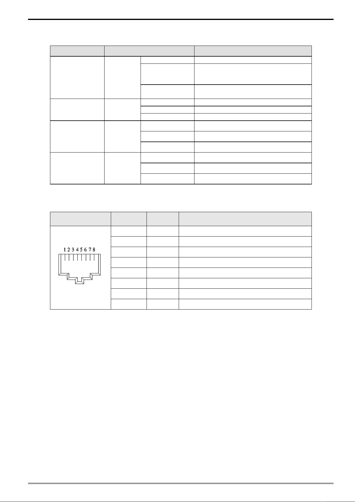
2.4 Definition of RJ45 Pin .........................................................................................................7
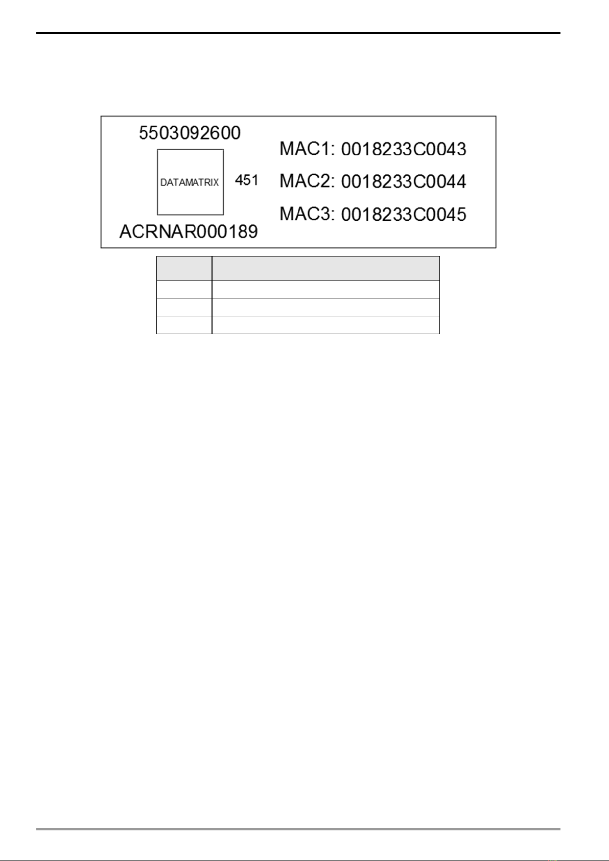
2.5 MAC Address Definition ......................................................................................................8
3Installation and Wiring ......................................................................................................9
3.1 Mounting Position of Communication Cards........................................................................9
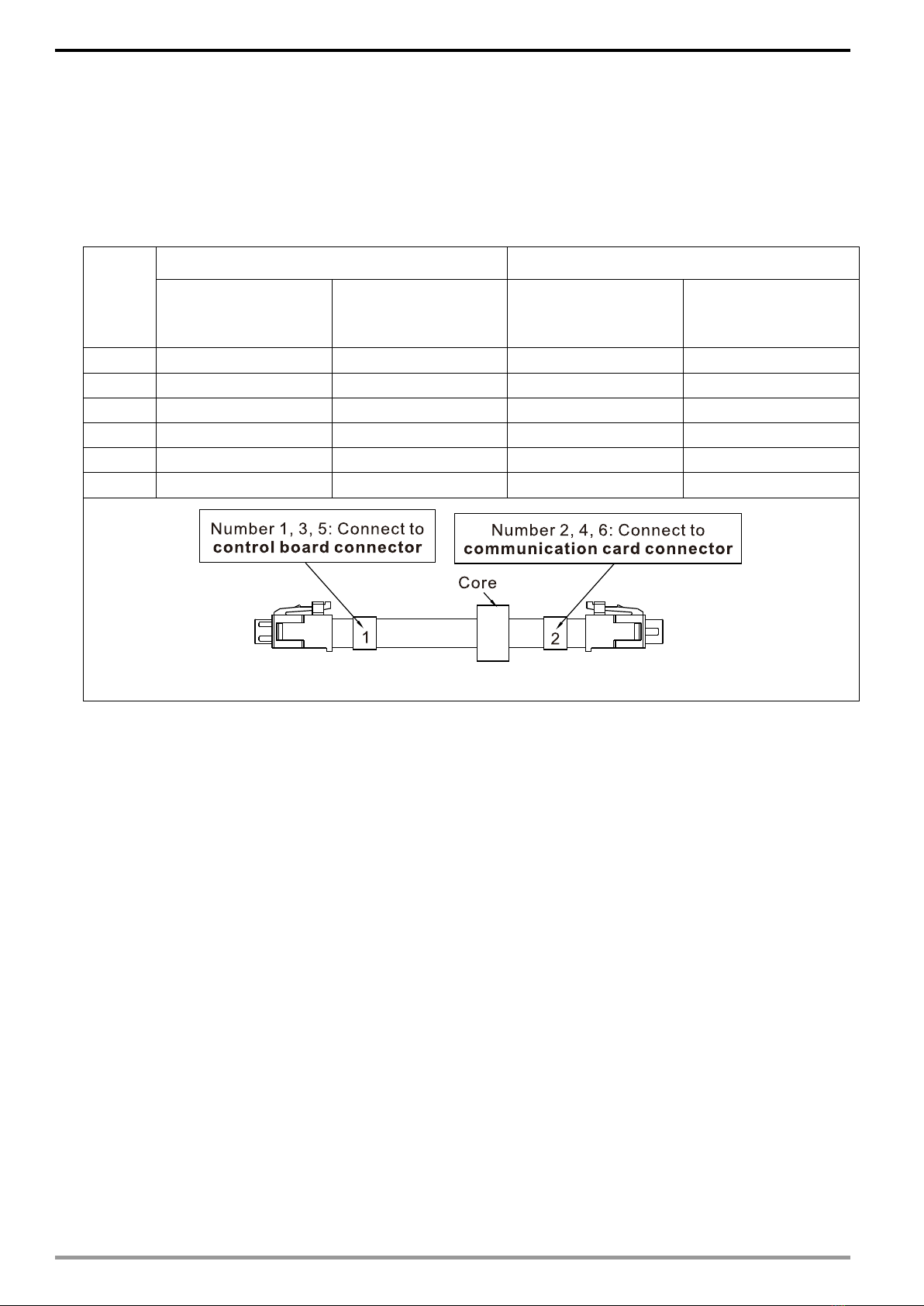
3.2 Communication Cable.......................................................................................................10
3.3 MS300 Installation ............................................................................................................11
3.4 MH300 Installation ............................................................................................................13
3.5 Connecting to the Network................................................................................................16
4MH300/MS300 Drive Settings .........................................................................................17
5PROFINET Communication Profile ................................................................................18
5.1 Profinet comm. card info. (Identification & Maintenance functions (I&M))..........................18
5.2 MS300/MH300 real-time data access method(List of control words and status words) .....19
5.3 Motor Drive Handling when Disconnection........................................................................21
6Connection Configuration to Host Controller...............................................................23
6.1 Basic Configuration...........................................................................................................23
6.2 Speed Mode DEMO (S7-300 + STEP 7) ...........................................................................28
6.3 Speed Mode DEMO (S7-1500 + TIA PORTAL) .................................................................38
6.4 Demonstration of Reading/Writing Synchronous and Asynchronous Parameters
(S7-300 + TIA PORTAL)............................................................................................................48

MS300/MH300 PROFINET Communication Card CMM-PN02
CMM-PN02 Operation Manual
4
1 Introduction
1.1 Introduction to PROFINET IO Communication
PROFINET IO is a fieldbus, a family of industrial computer network protocols, and serves
as a communication between programmable logic controllers (PLC) and distributed field
equipment for EtherNet. This protocol recognizes three classes of devices, IO
Controllers, IO Supervisors and IO Devices, and uses three different communication
channels to exchange data: Standard UDP/IP & TCP/IP Channel, Real-Time (RT)
Channel, and Isochronous Real-Time (IRT) Channel. Standard UDP/IP & TCP/IP
Channel is used to parameterize and configure device and asynchronous operation; RT
Channel is used for synchronous data transmission and warning; IRT Channel is
applied to motion control.
1.2 Features
CMM-PN02 connects MS300/MH300 drive to PROFINET to exchange data with the host
controller easily. This simple network solution saves cost and time for connection and
installation of factory automation. Moreover, its components are compatible with
suppliers’.
By installing CMM-PN02 in MS300/M300 through the main PROFINET device, you can:
1. Control the drive through PROFINET
2. Modify the drive’s parameters through PROFINET
3. Monitor the drive’s status through PROFINET
1.3 Network Functions and Specifications
EtherNet Specifications
Item Specifications
Interface RJ45
Number of ports 2 ports
Communication
Mode
IEEE 802.3
Cable Category 5e shielding 100 M
Transmission
speed
10/100 Mbps auto-negotiate
Communication
protocol
PROFINET
Environmental Conditions
Item Specifications
Noise immunity
ESD (IEC 61800-5-1, IEC 6100-4-2)
EFT (IEC 61800-5-1, IEC 6100-4-4)
Surge Test (IEC 61800-5-1, IEC 6100-4-5)
Conducted Susceptibility Test (IEC 61800-5-1, IEC 6100-4-6)
Operating
temperature
-10–50°C (temperature), 90% (humidity)
Storage
temperature
-25–70°C (temperature), 95% (humidity)
Vibration/Shock
resistance
International standards
IEC 61800-5-1, IEC 60068-2-6/IEC 61800-5-1, IEC 60068-2-27

MS300/MH300 PROFINET Communication Card CMM-PN02
CMM-PN02Operation Manual
5
Electrical Specifications
Item Specifications
Power supply
voltage
5 VDC
Power
consumption
0.8 W
Insulation voltage 500 VDC
Weight
(g; approx.)
27 (g)

MS300/MH300 PROFINET Communication Card CMM-PN02
CMM-PN02 Operation Manual
6
2 Product Appearance and Components
2.1 Exterior Dimensions
Unit: mm [inch]
2.2 Introduction to Each Component
1. Screw fastening hole 9.
Link PHY2 indicator (Port 2)
2. Positioning hole for communication card 10.F/W indicator
3. Control Panel connection port 11. D/B indicator
4. RJ45 connection port (Port 2) 12. PE grounding terminal
5. RJ45 connection port (Port 1)
6. BF out indicator
7. Ready out indicator
8. Link PHY1 indicator (Port 1)

MS300/MH300 PROFINET Communication Card CMM-PN02
CMM-PN02Operation Manual
7
2.3 LED Indicators
Name Indicator Status Indication
BF indicator Red LED
Always on
Disconnected with PROFINET Controller
Flashing
Normal connection, but abnormal
communication with PROFINET
Controller.
Off
Normal connection with PROFINET
Controller
RDY indicator Red/Green
LED
Always orange
Fault found on the Profinet comm. card.
Flashing
Profinet communication card is activating.
Always green
No fault found.
L/A1 indicator Green LED
Always on L/A1 has network signal.
Flashing L/A1 is handshaking data.
Off L/A1 doesn’t have network signal.
L/A2 indicator Green LED
Always on L/A2 has network signal.
Flashing rL/A2 is handshaking data
Off L/A2 doesn’t have network signal.
2.4 Definition of RJ45 Pin
RJ45 Pinout
Diagram
PIN Definition Description
1 Tx+ Positive pole for data transmission
2 Tx- Negative pole for data transmission
3 Rx+ Positive pole for receiving data
4 -- N/C
5 -- N/C
6 Rx- Negative pole for receiving data
7 -- N/C
8 -- N/C

MS300/MH300 PROFINET Communication Card CMM-PN02
CMM-PN02 Operation Manual
8
2.5 MAC Address Definition
Definition Description
MAC1 Port 1 MAC Address
MAC2 Port 2 MAC Address
MAC3 Interface MAC Address

MS300/MH300 PROFINET Communication Card CMM-PN02
CMM-PN02Operation Manual
9
3 Installation and Wiring
This section introduces how CMM-PN02 connects to MS300/MH300 and to network.
3.1 Mounting Position of Communication Cards
MS300 Mounting Position of Communication Card
Frame A–D Frame E and F
(Option card mounting box)
Fig. 3-1 Fig. 3-2
MH300 Mounting Position of Communication Card
Frame A–D (Option card mounting box) Frame E and F
(Option card mounting box)
Fig. 3-3 Fig. 3-4

MS300/MH300 PROFINET Communication Card CMM-PN02
CMM-PN02 Operation Manual
10
3.2 Communication Cable
Three types of cable length are available. As shown in the Fig.3-5, there are
numbers on two ends of the communication cable near the connector. The
connection methods of the communication card for different frames are shown in the
table below. Read the descriptions and numbers on the cables before wiring.
Frame
Mounting Position 1 Mounting Position 2
Connect to
control board
connector
Connect to
communication
card connector
Connect to
control board
connector
Connect to
communication
card connector
A
1
2
3
4
B
1
2
3
4
C
3
4
3
4
D
5
6
5
6
E
3
4
3
4
F
3
4
3
4
Fig. 3-5

MS300/MH300 PROFINET Communication Card CMM-PN02
CMM-PN02Operation Manual
11
3.3 MS300 Installation
3.3.1 MS300 Mounting Position 1 (See Section 3.1 for Details on Mounting Position) -
Frame A–F
Installation method: Back-mount the communication card by connecting flat cablesto
the control board.
Turn off the power of the motor drive, and then remove the front cover, as shown in Fig.3-6.
Assemble the connection cable: Connect the connector at one end of the connection cable
to the control board connector. Refer to Section 3.2 for more information on connection
methods.
Assemble the supported frame of the option card: Aim the two clips at the two slots on the
motor drive, and then press downward to have the two clips engage the slots, as shown in
Fig.3-7.
Assemble the connection cable: Connect the connector at the other end of the connection
cable to the connector of the communication card.
Assemble the communication card: Have the terminal block and connector of the
communication card face downward, aim the two holes of the communication card to the
position column and press downward so that the three clips engage the communication card,
as shown in Fig.3-8.
Make sure that three clips properly engage the communication card and then tighten the
screws (suggested torque value: 4–6 kg-cm [3.5–5.2 lb-in.] [0.39–0.59 Nm]), as shown in
Fig.3-9.
Assembly is completed, as shown in Fig.3-10.
Step1: Remove the front cover Step 2: Assemble the supported frame
Fig. 3-6 Fig. 3-7
Step 3: Assemble the
communication card
Step 4: Tighten the
screws
Step 5: Assembly
completed
Fig. 3-8 Fig. 3-9 Fig. 3-10

MS300/MH300 PROFINET Communication Card CMM-PN02
CMM-PN02 Operation Manual
12
3.3.2 MS300 Mounting Position 2 (See Section 3.1 for Details on Mounting Position) -
Frame A–D (Not Applicable for Frame E and F)
Installation method: Front-mount the communication card by connecting flat cables to
the control board.
Turn off the power of the motor drive, and then remove the front cover, as shown in Fig.3-11.
Assemble the communication card: Detach the upper cover of the mounting box for the
communication card by slipping and make the terminal block and connector of the
communication card face upward. Fix the front end of the communication card to the slots,
and then rotate it, as shown in the Fig.3-12.
Make sure that two clips properly engage the communication card on the backside, and then
tighten the screws (suggested torque value: 4–6 kg-cm [3.5–5.2 lb-in.] [0.39–0.59 Nm]), as
shown in Fig.3-13.
Assemble the connection cable: Connect the connector at one end of the connection cable
to the control board connector. Refer to Section 3.2 for more information on connection
methods.
Attach the front cover of the drive.
Assemble the connection cable: Connect the connector at the other end of the connection
cable to the connector of the communication card.
Attach the upper cover to the mounting box for the option card, as shown in Fig.3-14.
Assemble the mounting box for the option card: Aim the four clips of the mounting box for
the option card at the slots on the upper cover of the motor drive, and then press downward
to have the four clips engage the slots, as shown in the Fig.3-15.
Assembly is completed, as shown in Fig.3-16.
Step1: Remove the
front cover
Step 2: Assemble the
communication card
Step 3: Tighten the
screws
Fig. 3-11 Fig. 3-12 Fig. 3-13
Step 4: Attach the upper
cover to the mounting box
Step 5: Assemble the mounting
box for the option card
Step 5: Assembly
completed
Fig. 3-14
Fig. 3-15 Fig. 3-16

MS300/MH300 PROFINET Communication Card CMM-PN02
CMM-PN02Operation Manual
13
3.4 MH300 Installation
3.4.1 MH300 Mounting Position 1 (See Section 3.1 for Details on Mounting Position) -
Frame A–F
Installation method: Back-mount the communication card by connecting flat cables to
the control board.
Turn off the power of the motor drive, and then remove the front cover, as shown in Fig.3-17.
Assemble the connection cable: Connect the connector at one end of the connection cable
to the control board connector. Refer to Section 3.2 for more information on connection
methods.
Assemble the supported frame of the option card: Aim the two clips at the two slots on the
motor drive, and then press downward to have the two clips engage the slots, as shown in
Fig.3-18.
Assemble the connection cable: Connect the connector at the other end of the connection
cable to the connector of the communication card.
Assemble the communication card: Have the terminal block and connector of the
communication card face downward, aim the two holes of the communication card to the
position column and press downward so that the three clips engage the communication card,
as shown in Fig.3-19.
Make sure that three clips properly engage the communication card, and then tighten the
screws (suggested torque value: 4–6 kg-cm [3.5–5.2 lb-in.] [0.39–0.59 Nm]), as shown in
Fig.3-20.
Assembly is completed, as shown in Fig.3-21.
Step1: Remove the front cover Step 2: Assemble the supported frame
Fig. 3-17
Fig. 3-18

MS300/MH300 PROFINET Communication Card CMM-PN02
CMM-PN02 Operation Manual
14
3.4.2 MH300 Mounting Position 2 (See Section 3.1 for Details on Mounting Position) -
Frame A–D
Installation method: Front-mount the communication card by connecting flat cables to
the control board.
Turn off the power of the motor drive, and then remove the front cover, as shown in Fig.3-22.
Assemble the communication card: Detach the upper cover of the mounting box for the
communication card by slipping and make the terminal block and connector of the
communication card face upward. Fix the front end of the communication card to the slots,
and then rotate it, as shown in the Fig.3-23.
Make sure that two clips properly engage the communication card on the backside, and then
tighten the screws (suggested torque value: 4–6 kg-cm [3.5–5.2 lb-in.] [0.39–0.59 Nm]), as
shown in Fig.3-24.
Assemble the connection cable: Connect the connector at one end of the connection cable
to the control board connector. Refer to Section 3.2 for more information on connection
methods.
Attach the front cover of the drive.
Assemble the connection cable: Connect the connector at the other end of the connection
cable to the connector of the communication card.
Attach the upper cover to the mounting box for the option card, as shown in Fig.3-25.
Assemble the mounting box for the option card: Aim the four clips of the mounting box for
the option card at the slots on the upper cover of the motor drive, and then press downward
to have the four clips engage the slots, as shown in the Fig.3-26.
Assembly is completed, as shown in Fig.3-27.
Step1: Remove the
front cover
Step 3: Assemble the
communication card
Step 4: Tighten the
screws
Fig. 3-22
Fig. 3-23 Fig. 3-24
Step 4: Attach the upper
cover to the mounting box
Step 5: Assemble the mounting
box for the option card
Step 5: Assembly
completed
Fig. 3-25
Fig. 3-26 Fig. 3-27

MS300/MH300 PROFINET Communication Card CMM-PN02
CMM-PN02Operation Manual
15
3.4.3 MH300 Mounting Position 2 (See Section 3.1 for Details on Mounting Position) -
Frame E and F
Installation method: Front-mount the communication card by connecting flat cables to
the control board.
Turn off the power of the motor drive, and then remove the front cover, as shown in Fig.3-28.
Assemble the connection cable: Connect the connector at one end of the connection cable
to the control board connector. Refer to Section 3.2 for more information on connection
methods. Wire the cables as Fig.3-29 shows and make sure the core is placed in the
groove.
Assemble the communication card: Have the terminal block and connector of the
communication card face upward. Fix the front end of the communication card to the slots,
and then rotate it, as shown in the Fig.3-30.
Make sure that the clip properly engages the communication card, and then tighten the
screws (suggested torque value: 4–6 kg-cm [3.5–5.2 lb-in.] [0.39–0.59 Nm]), as shown in
Fig.3-31.
Assemble the connection cable: Connect the connector at the other end of the connection
cable to the connector of the communication card, as shown in Fig.3-32.
Assembly is completed, as shown in Fig.3-33.
Step1: Remove the
front cover
Step 2: Assemble the
connection cable
Step 3: Assemble the
communication card
Fig. 3-28
Fig. 3-29
Fig. 3-30
Step 4: Tighten the
screws
Step 5: Assemble the
connection cable
Step 6: Assembly
completed
Fig. 3-31
Fig. 3-32
Fig. 3-33

MS300/MH300 PROFINET Communication Card CMM-PN02
CMM-PN02 Operation Manual
16
3.5 Connecting to the Network
The wiring of CMM-PN02:
When the installation is finished, supply electricity to the drive. The Pr.09-60 of the drive
should be able to display “PROFINET” with a current value of 12. If not, make sure your
version of the drive is correct (MS300/MH300 needs v.2.04 or later versions) and the
communication card is correctly connected.

MS300/MH300 PROFINET Communication Card CMM-PN02
CMM-PN02Operation Manual
17
4 MH300/MS300 Drive Settings
When you operate MS300/MH300 through CMM-PN02, you should set the
communication card as the source of MS300/MH300 controls and settings. You need to
use the keypad to configure the following parameter addresses to the corresponding
values:
NOTE: To make PLC or the host controller to identify CMM-PN02, it is necessary to load the product
description file of CMM-PN02 (GSDML). You can download it directly from Delta’s official website.
Keypad
Parameter No.
Settings/
Displayed Value
Description of Function
Pr.00-20 8 Set communication card as the source of frequency command.
Pr.00-21 5 Set communication card as the source of control.
Pr.09-30 1 Decoding method is either 60xx or 20xx.
Pr.09-60 12
Communication card identification:
When CMM-PN02 communication card is connected, the value of
this parameter displays “12”.

MS300/MH300 PROFINET Communication Card CMM-PN02
CMM-PN02 Operation Manual
18
5 PROFINET Communication Profile
This section describes the general setting model and the way to set the parameters of the
motor drives by the host computer through CMM-PN02, refer to the following sections for the
actual operations. This section is divided into the following items:
1. Profinet comm. card info. (Identification & Maintenance functions (I&M))
2. MS300/MH300 real-time data access method
3. Motor drive handling during disconnection in synchronous mode
4. MS300/MH300 parameter reading and writing in non-real-time mode
5.1 Profinet comm. card info. (Identification & Maintenance functions (I&M))
Profinet provides Identification and Maintenance function (I&M) which supports machinery
commissioning, parameter tuning and repairing. CMM-PN02 supports the I&M0 function
which can be accessed using a read request from the I&M record.
The following table shows the data structure when I&M0 record is returned:
Content
Size
Description
Header
10 bytes
-
Vendor ID
2 bytes
PROFINET Vendor ID of Delta, which is 0x03FB.
Order ID
20 bytes
Order number
Serial number
16 bytes
Serial number
Hardware revision
2 bytes
Hardware revision
Software revision
4 bytes
Revision of the software
Revision counter
2 bytes
Number of revisions
Profile ID
2 bytes
0x00
Profile specific type
2 bytes
No profile specific type (0x0000)
I&M version
2 bytes
Version 1.1 (0x0101)
Supported I&M functions
2 bytes
I&M0 is supported (0x0001).

MS300/MH300 PROFINET Communication Card CMM-PN02
CMM-PN02Operation Manual
19
5.2 MS300/MH300 real-time data access method(List of control words and
status words)
Profinet communication provides a real-time channel (RT channel) for data transmission.
After the host computer establishes this channel with the communication card, it can send
and receive the data from the motor drive during a fixed period of time. CMM-PN02
provides the host computer with 60 bytes of input and output data through this channel
according to the setting at Pr.09-30 of the motor drive. The corresponding methods are
listed in the table below:
Output of host computer
Corresponding Address at
the motor drive.
Address Number Pr.09-30 = 0 Pr.09-30 = 1
%Q (x + 0) ~ %Q (x + 1) 2000H 6000H
%Q (x + 2) ~ %Q (x + 3) 2001H 6001H
%Q (x + 4) ~ %Q (x + 5) 2002H 6002H
%Q (x + 6) ~ %Q (x + 7) N/A 6003H
%Q (x + 8) ~ %Q (x + 9) N/A 6004H
%Q (x + 10) ~ %Q (x + 11) N/A 6005H
%Q (x + 12) ~ %Q (x + 13)
N/A 6006H
%Q (x + 14) ~ %Q (x + 15) N/A N/A
… N/A N/A
%Q (x + 40) ~ %Q (x + 41) user-defined address 1 user-defined address 1
… user-defined address n user-defined address n
%Q (x + 54) ~ %Q (x + 55) user-defined address 8 user-defined address 8
%Q (x + 56) ~ %Q (x + 57) N/A N/A
%Q (x + 58) ~ %Q (x + 59) N/A N/A
NOTE 1: x is the start address set by the host computer.
NOTE 2: The Q means output, one motor drive address corresponds to two bytes, and one host computer
address corresponds to one byte in order of low byte to high byte.
NOTE 3: user-defined address can define the address of the motor drive in the host computer, for example,
Pr.04-50 = 16#0432 = 1074, the more addresses are defined, the longer the synchronization time between the
motor drive and the host computer. You can define the user-defined address in the TIA portal. Refer to the
periodic communication in the next chapter.

MS300/MH300 PROFINET Communication Card CMM-PN02
CMM-PN02 Operation Manual
20
Input of host computer
Corresponding Address at
the motor drive.
Address Number Pr.09-30 = 0 Pr.09-30 = 1
%I (y + 0) ~ %I (y + 1) 2100H 6100H
%I (y + 2) ~ %I (y + 3) 2101H 6101H
%I (y + 4) ~ %I (y + 5) 2102H 6102H
%I (y + 6) ~ %I (y + 7) 2103H 6103H
%I (y + 8) ~ %I (y + 9) 2104H 6104H
%I (y + 10) ~ %I (y + 11) 2105H 6105H
%I (y + 12) ~ %I (y + 13) 2106H 6106H
%I (y + 14) ~ %I (y + 15) 2107H N/A
… 210xH N/A
%I (y + 30) ~ %I (y + 31)
210FH N/A
%I (y + 32) ~ %I (y + 33)
N/A N/A
… N/A N/A
%I (y + 40) ~ %I (y + 41) user-defined address 1 user-defined address 1
… user-defined address n user-defined address n
%I (y + 54) ~ %I (y + 55) user-defined address 8 user-defined address 8
%I (y + 56) ~ %I (y + 57) N/A N/A
%I (y + 58) ~ %I (y + 59) N/A N/A
NOTE 1: y is the start address of the host computer.
NOTE 2: The I means input, one motor drive address corresponds to two bytes, and one host computer
address corresponds to one byte in order of low byte to high byte.
NOTE 3: User-defined address can define the address of the motor drive in the host computer. For example,
Pr.04-50 = 16#0432 = 1074. The more addresses are defined, the longer the synchronization time between the
motor drive and the host computer. You can define the user-defined address in the TIA portal. Refer to the
periodic communication in the next chapter.
Refer to the MS300/MH300 user manual for more information on the 200xH, 210xH, 600xH, 610xH addresses
mentioned in the table above.
Other manuals for MS300 Series
3
This manual suits for next models
2
Table of contents
Other Delta Conference System manuals