Delta AC Motor Drives VFD-XXXE User manual

English- 1
Preface
Thank you for choosing DELTA’s high-performance VFD-E Series. The VFD-E Series is
manufactured with high-quality components and materials and incorporate the latest microprocessor
technology available.
Getting Started
This quick start will be helpful in the installation and parameter setting of the AC motor drives. To
guarantee safe operation of the equipment, read the following safety guidelines before
connecting power to the AC motor drives. For detail information, refer to the VFD-E User Manual
on the CD supplied with the drive.
DANGER!
1. AC input power must be disconnected before any wiring to the AC motor drive is made.
2. A charge may still remain in the DC-link capacitors with hazardous voltages, even if the power has
been turned off. To prevent personal injury, please ensure that power has turned off before opening the
AC motor drive and wait ten minutes for the capacitors to discharge to safe voltage levels.
3. Never reassemble internal components or wiring.
4. The AC motor drive may be destroyed beyond repair if incorrect cables are connected to the
input/output terminals. Never connect the AC motor drive output terminals U/T1, V/T2, and W/T3
directly to the AC mains circuit power supply.
5. Ground the VFD-E using the ground terminal. The grounding method must comply with the laws of the
country where the AC motor drive is to be installed. Refer to the Basic Wiring Diagram.
6. VFD-E series is used only to control variable speed of 3-phase induction motors, NOT for 1-phase
motors or other purpose.
7. VFD-E series is the specific drive for the elevator door and other automatic door control, NOT for those
devices that may cause personal injury, such as life support equipment or any life safety situation.
8. To prevent drive damage, the RFI jumper connected to ground shall be cut off if the AC motor drive is
installed on an ungrounded power system or a high resistance-grounded (over 30 ohms) power system
or a corner grounded TN system.
WARNING!
1. DO NOT use Hi-pot test for internal components. The semi-conductor used in AC motor drive easily
damage by high-pressure.
2. There are highly sensitive MOS components on the printed circuit boards. These components are
especially sensitive to static electricity. To prevent damage to these components, do not touch these
components or the circuit boards with metal objects or your bare hands.
3. Only quality person is allowed to install, wire and maintain AC motor drive.
CAUTION!
1. Some parameters settings can cause the motor to run immediately after applying power.
2. DO NOT install the AC motor drive in a place subjected to high temperature, direct sunlight, high
humidity, excessive vibration, corrosive gases or liquids, or airborne dust or metallic particles. Only use
AC motor drives within specification. Failure to comply may result in fire, explosion or electric shock. To
prevent personal injury, please keep children and unqualified people away from the equipment.
3. When the motor cable between AC motor drive and motor is too long, the layer insulation of the motor
may be damaged. Please use a frequency inverter duty motor or add an AC output reactor to prevent
damage to the motor. Refer to appendix B Reactor for details.
4. The rated voltage for AC motor drive must be ≤240V and the mains supply current capacity must be
≤5000A RMS.

English- 2
Specifications
Voltage Class 115V Class
Model Number VFD-XXXE 002 004 007
Max. Applicable Motor Output (kW) 0.2 0.4 0.75
Max. Applicable Motor Output (hp) 0.25 0.5 1.0
Rated Output Capacity (kVA) 0.6 1.0 1.6
Rated Output Current (A) 1.6 2.5 4.2
Maximum Output Voltage (V) 3-Phase Proportional to Twice the Input Voltage
Output Frequency (Hz) 0.1~600 Hz
Output Rating
Carrier Frequency (kHz) 1-15
Single-phase
Rated Input Current (A) 6 9 18
Rated Voltage/Frequency Single phase, 100-120V, 50/60Hz
Voltage Tolerance ±10%(90~132 V)
Input Rating
Frequency Tolerance ±5%(47~63 Hz)
Cooling Method Natural Cooling Fan Cooling
Weight (kg) 1.2 1.2 1.2
Voltage Class 230V Class
Model Number VFD-XXXE 002 004 007 015 022 037 055 075
Max. Applicable Motor Output (kW) 0.2 0.4 0.75 1.5 2.2 3.7 5.5 7.5
Max. Applicable Motor Output (hp) 0.25 0.5 1.0 2.0 3.0 5.0 7.5 10
Rated Output Capacity (kVA) 0.6 1.0 1.6 2.9 4.2 6.5 9.5 12.5
Rated Output Current (A) 1.6 2.5 4.2 7.5 11.0 17 25 33
Maximum Output Voltage (V) 3-Phase Proportional to Input Voltage
Output Frequency (Hz) 0.1~600 Hz
Output Rating
Carrier Frequency (kHz) 1-15
Single/3-phase 3-phase
Rated Input Current (A) 4.9/1.9 6.5/2.7 9.5/5.1 15.7/9 24/15 20.6 26 34
Rated Voltage/Frequency Single/3-phase
200-240 V, 50/60Hz
3-phase
200-240V, 50/60Hz
Voltage Tolerance ±10%(180~264 V)
Input Rating
Frequency Tolerance ±5%(47~63 Hz)
Cooling Method Natural Cooling Fan Cooling
Weight (kg) 1.1 1.1 1.1 *1.2/1.9 1.9 1.9 3.5 3.5
*NOTE: the weight for VFD015E23P is 1.2kg.
Voltage Class 460V Class
Model Number VFD-XXXE 004 007 015 022 037 055 075 110
Max. Applicable Motor Output (kW) 0.4 0.75 1.5 2.2 3.7 5.5 7.5 11
Max. Applicable Motor Output (hp) 0.5 1.0 2.0 3.0 5.0 7.5 10 15
Rated Output Capacity (kVA) 1.2 2.0 3.3 4.4 6.8 9.9 13.7 18.3
Rated Output Current (A) 1.5 2.5 4.2 5.5 8.2 13 18 24
Maximum Output Voltage (V) 3-Phase Proportional to Input Voltage
Output Frequency (Hz) 0.1~600 Hz
Output Rating
Carrier Frequency (kHz) 1-15
3-phase
Rated Input Current (A) 1.9 3.2 4.3 7.1 11.2 14 19 26
Rated Voltage/Frequency 3-phase, 380-480V, 50/60Hz
Voltage Tolerance
±
10%(342~528V)
Input Rating
Frequency Tolerance ±5%(47~63Hz)
Cooling Method Natural Cooling Fan Cooling
Weight (kg) 1.2 1.2 1.2 1.9 1.9 4.2 4.2 4.2

English- 3
General Specifications
Control System SPWM(Sinusoidal Pulse Width Modulation) control (V/f or sensorless vector
control)
Frequency Setting Resolution 0.01Hz
Output Frequency Resolution 0.01Hz
Torque Characteristics Including the auto-torque/auto-slip compensation; starting torque can be 150%
at 3.0Hz
Overload Endurance 150% of rated current for 1 minute
Skip Frequency Three zones, setting range 0.1-600Hz
Accel/Decel Time 0.1 to 600 seconds (2 Independent settings for Accel/Decel time)
Stall Prevention Level Setting 20 to 250% of rated current
DC Brake Operation frequency 0.1-600.0Hz, output 0-100% rated current
Start time 0-60 seconds, stop time 0-60 seconds
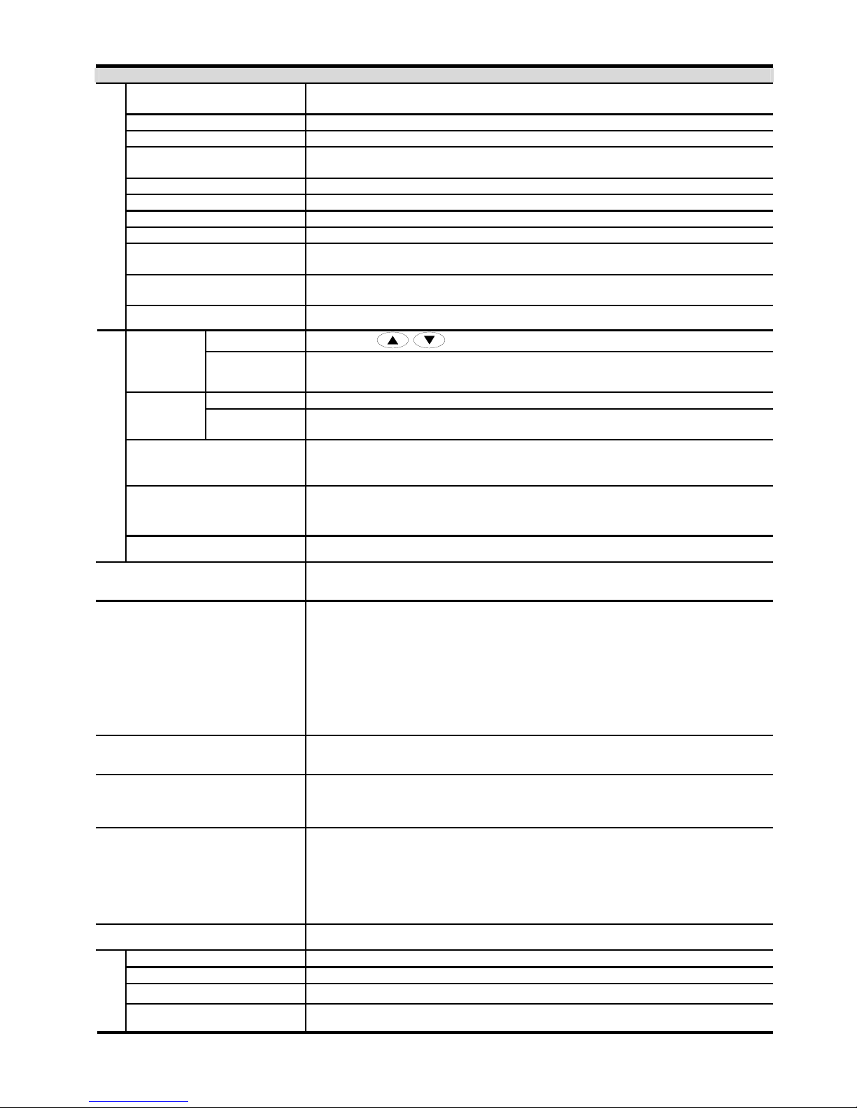
Regenerated Brake Torque Approx. 20% (up to 125% possible with optional brake resistor or externally
mounted brake unit, 1-15hp (0.75-11kW) models have brake chopper built-in)
Control Characteristics
V/f Pattern 4-point adjustable V/f pattern
Keypad Setting by
Frequency
Setting External Signal Potentiometer-5kΩ/0.5W, 0 to +10VDC, 4 to 20mA, RS-485 interface; Multi-
function Inputs 3 to 9 (15 steps, Jog, up/down)
Keypad Set by RUNand STOPOperation
Setting
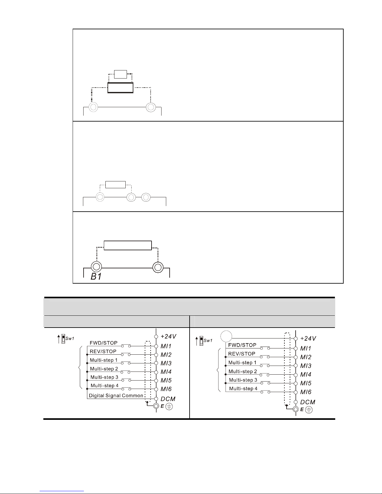
Signal External Signal 2 wires/3 wires ((MI1, MI2, MI3)), JOG operation, RS-485 serial interface
(MODBUS), programmable logic controller
Multi-function Input Signal
Multi-step selection 0 to 15, Jog, accel/decel inhibit, 2 accel/decel switches,
counter, , external Base Block, ACI/AVI selections, driver reset, UP/DOWN key
settings, NPN/PNP input selection
Multi-function Output
Indication
AC drive operating, frequency attained, zero speed, Base Block, fault indication,
overheat alarm, emergency stop and status selections of input terminals
Operating Characteristics
Analog Output Signal Output frequency/current
Alarm Output Contact Contact will be On when drive malfunctions (1 Form C/change-over contact and
1 open collector output) for standard type)
Operation Functions
Built-in PLC(NOT for CANopen models), AVR, accel/decel S-Curve, over-
voltage/over-current stall prevention, 5 fault records, reverse inhibition,
momentary power loss restart, DC brake, auto torque/slip compensation, auto
tuning, adjustable carrier frequency, output frequency limits, parameter
lock/reset, vector control, PID control, external counter, MODBUS
communication, abnormal reset, abnormal re-start, power-saving, fan control,
sleep/wake frequency, 1st/2nd frequency source selections, 1st/2nd frequency
source combination, NPN/PNP selection, parameters for motor 0 to motor 3,
DEB and OOB (Out Of Balance Detection)(for washing machine)
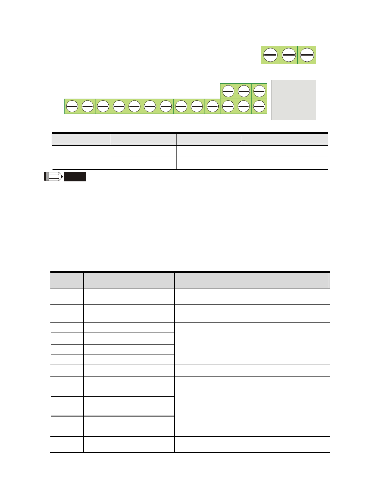
Protection Functions Over voltage, over current, under voltage, external fault, overload, ground fault,
overheating, electronic thermal, IGBT short circuit, PTC
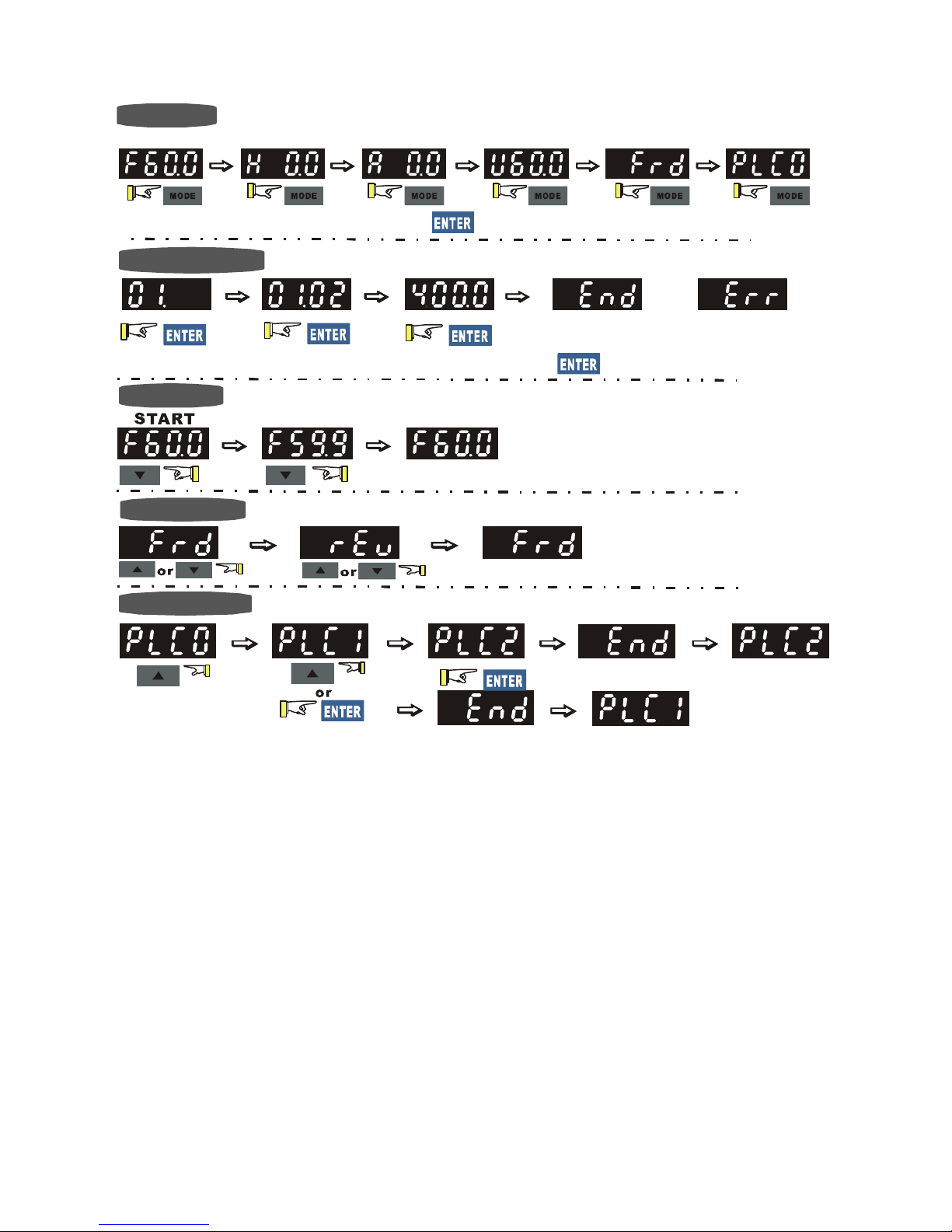
Display Keypad (optional)
6-key, 7-segment LED with 4-digit, 5 status LEDs, master frequency, output
frequency, output current, custom units, parameter values for setup and lock,
faults, RUN, STOP, RESET, FWD/REV, PLC
Built-in Brake Chopper
VFD002E11T/21T/23T, VFD004E11T/21T/23T/43T,
VFD007E21T/23T/43T, VFD015E23T/43T, VFD007E11A, VFD015E21A,
VFD022E21A/23A/43A, VFD037E23A/43A VFD007E11C, VFD015E21C,
VFD022E21C/23C/43C, VFD037E23C/43C, VFD055E23A/43A,
VFD075E23A/43A, VFD110E43A, VFD055E23C/43C, VFD075E23C/43C,
VFD110E43C
Built-in EMI Filter For 230V 1-phase and 460V 3-phase models.
Enclosure Rating IP20
Pollution Degree 2
Installation Location Altitude 1,000 m or lower, keep from corrosive gasses, liquid and dust
Enviromental
Conditions
Ambient Temperature -10oC to 50oC (40oC for side-by-side mounting) Non-Condensing and not frozen

English- 4
Storage/ Transportation
Temperature -20 oC to 60 oC
Ambient Humidity Below 90% RH (non-condensing)
Vibration 9.80665m/s2(1G) less than 20Hz, 5.88m/s2 (0.6G) at 20 to 50Hz
Approvals
Basic Wiring Diagram
Users must connect wiring according to the following circuit diagram shown below.
AVI
ACI
ACM
+
4~20mA
+10V
5K
3
2
1
Power supply
+10V 3mA
Master Frequency
0 to 10V 47K
Analog Signal Common E
Main circ uit (power) terminals Control circuit terminals Shielded leads & Cable
* Don't apply the mains voltage directly
to above terminals.
E
R(L1)
S(L2)
T(L3)
Fuse/NFB(None Fuse Breaker)
SA
OFF ON
MC
MC
RB
RC
Recommended Circuit
when power supply
is turned OFF by a
fault output
If the fault occurs, the
con tact will be O N t o
turn off the power and
protect the power system.
R(L1)
S(L2)
T(L3)
E
Analog Multi-function Output
Terminal
factory setting: Analog freq.
/ c ur re nt meter
0~10VDC/2mA
U(T1)
V(T2)
W(T3)
IM
3~
AFM
ACM
RA
RB
RC
Motor
Factory setting:
Drive is in operation
48V50mA
Multi-function
Photocoulper Output
Analog Signal common
E
E
Refer to Control
Terminal Explanation
MO1
MCM
MI1
MI2
MI3
MI4
MI6
MI5
DCM
+24V
FWD/Stop
REV/Stop
Multi-step 1
Multi-step 2
Multi-step 3
Multi-step 4
Digital Signal Common
Factory
setting
Sw2
AVI
ACI
Factory setting:
ACI Mode
ACI/AVI switch
When switching to AVI,
it indicates AVI2
-
81
Sw1
NPN
PNP
Factory setting:
NPN Mode
Please refer to following
figure for wiring of NPN
mode and PNP mode.
Brake resistor/unit (optional)
Refer to user manual for the use
of special brake resistor/unit.
The wiring for the models
may be different. Refer to
following figures for detail.
* Single-phase models can only use R(L1), S(L2) to be the power terminals.
* Single-phase power cannot be used for 3-phase models.
BUE
Brake unit
(optional)
BR brake re sistor
(optional)
RS-485 serial interface
(NOT for VFD*E*C models)
1: Reserved
2: EV
5: SG+
6: Reserved
7: Reserved
8: Reserved
3: GND
4: SG -
For VFD*E*C models,
please refer to figure 5.

English- 5
+
-
Please use brake unit and/or
brake resistor depending on
type and application
Bra ke unit
(optional)
BUE
BR brake resistor
(optional)
Figure 1 for models of VFD-E Series
VFD002E11A/21A/23A, VFD004E11A/21A/23A/43A, VFD007E21A/23A/43A,
VFD015E23A/43A, VFD002E11C/21C/23C, VFD004E11C/21C/23C/43C,
VFD007E21C/23C/43C, VFD015E23C/43C, VFD002E11P/21P/23P,
VFD004E11P/21P/23P/43P, VFD007E21P/23P/43P, VFD015E23P/43P
Please use brake unit and/or
brake resistor depending on
type and application
+/B1
-
brake resistor
(optional)
BR
B2
Figure 2 for models of VFD-E Series
VFD007E11A, VFD015E21A, VFD022E21A/23A/43A, VFD037E23A/43A,
VFD055E23A/43A, VFD075E23A/43A, VFD110E43A, VFD007E11C,
VFD015E21C, VFD022E21C/23C/43C, VFD037E23C/43C,
VFD055E23C/43C, VFD075E23C/43C, VFD110E43C
Please use brake resistor
depending on type and
application
Figure 3 for models of VFD-E Series
V
FD002E11T/21T/23T, VFD004E11A/21T/23T/43T,
VFD007E21T/23T/43T, VFD015E23T/43T
B2
BR
brake resistor
(optional)
Figure 4 Wiring for NPN Mode and PNP Mode
A. NPN mode without external power B. NPN mode with external power
Factory
setting
NPN
PNP
Factory
setting
NPN
PNP
24
Vdc
-
+

English- 6
C. PNP mode without external power D. PNP mode with external power
Sw1
Factory
setting
NPN
PNP
Sw1
Factory
setting
NPN
PNP
24
Vdc
-
+
Figure 5 RJ-45 Pins Definition for VFD*E*C Models
PIN Signal Description
1 CAN_H CAN_H bus line (dominant high)
2 CAN_L CAN_L bus line (dominant low)
3 CAN_GND Ground / 0V /V-
4 SG+ 485 communication
5 SG- 485 communication
7 CAN_GND Ground / 0V /V-
Description of the Digital Keypad KPE-LE02 (Optional)
LED Display
Indicates frequency, voltage, current, user
defined units and etc.
Status Displa
y
Display the driver's current status.
STOP/RESET
Stops AC drive operation and reset the drive
after fault occurred.
RUN Key
Start AC drive operation.
MODE
Change between different display mode.
UP and DOWN Key
Set the parameter number and changes the
numerical data, such as Master Frequency.
Potentiometer
For master Frequency setting.
1
2
3
4
5
6
7
2
3
4
5
6
78
8
ENTER
Used to enter/modify programming
parameters
1

English- 7
Operation Steps of the Digital Keypad
To sh ift d ata
Setting PLC Mode
Setting Mode
Setting direction
(When operation source is digital keypad)
START
GO START
enter PLC2 mode
enter PLC1 mode
NOTE
:
In the parameter setting mode, you can press to return the selecting mode.
NOTE: In the selection mode, press to set the parameters.
Setting parameters
Success to
set parameter. Input data error
or

English- 8
Power Terminals and Control Terminals
Frame A Frame B Frame C
Frame Power Terminals Torque Wire Wire Type
R/L1, S/L2, T/L3
A
U/T1, V/T2, W/T3,
14kgf-cm
(12in-lbf)
12-14 AWG.
(3.3-2.1mm2) Copper only, 75oC
R/L1, S/L2, T/L3
U/T1, V/T2, W/T3
B
+/B1, B2, -,
18kgf-cm
(15.6in-lbf)
8-18 AWG.
(8.4-0.8mm2) Copper only, 75oC
R/L1, S/L2, T/L3
U/T1, V/T2, W/T3
C
+/B1, B2, -
30kgf-cm
(26in-lbf)
8-16 AWG.
(8.4-1.3mm2) Copper only, 75oC
NOTE
For frame C: To connect 6 AWG (13.3 mm2) wires, use Recognized Ring Terminals
Terminal Explanations
Terminal Symbol Explanation of Terminal Function
R/L1, S/L2, T/L3 AC line input terminals (1-phase/3-phase)
U/T1, V/T2, W/T3 AC drive output terminals for connecting 3-phase induction motor
+/B1~ B2 Connections for Brake resistor (optional)
+/B1, - Connections for External Brake unit (BUE series)
Earth connection, please comply with local regulations.

English- 9
The Specification for the Control Terminals
RS-485 port
10VMI1 MI2 MI3 MI4 MI5 MI6
DCM
24V
DCM
A
CM
AVI ACI
AFM MCM MO1
RA RB RC
The position of the control terminals
Terminals 2
Terminals 1
Frame Control Terminals Torque Wire
Terminals 1 5 kgf-cm (4.4 in-lbf) 12-24 AWG (3.3-0.2mm2)
A, B, C Terminals 2 2 kgf-cm (2 in-lbf) 16-24 AWG (1.3-0.2mm2)
NOTE
Frame A: VFD002E11A/21A/23A, VFD004E11A/21A/23A/43A, VFD007E21A/23A/43A,
VFD015E23A/43A, VFD002E11C/21C/23C, VFD004E11C/21C/23C/43C,
VFD007E21C/23C/43C, VFD015E23C/43C, VFD002E11T/21T/23T,
VFD004E11T/21T/23T/43T, VFD007E21T/23T/43T, VFD015E23T/43T,
VFD002E11P/21P/23P, VFD004E11P/21P/23P/43P, VFD007E21P/23P/43P,
VFD015E23P/43P
Frame B: VFD007E11A, VFD015E21A, VFD022E21A/23A/43A, VFD037E23A/43A
Frame C: VFD055E23A/43A, VFD075E23A/43A, VFD110E43A
Control Terminals Explanations
Terminal
Symbol Terminal Function Factory Settings (NPN mode)
ON: Connect to DCM
MI1 Forward-Stop command ON: Run in MI1 direction
OFF: Stop acc. to Stop Method
MI2 Reverse-Stop command ON: Run in MI2 direction
OFF: Stop acc. to Stop Method
MI3 Multi-function Input 3
MI4 Multi-function Input 4
MI5 Multi-function Input 5
MI6 Multi-function Input 6
Refer to Pr.04.05 to Pr.04.08 for programming the
Multi-function Inputs.
ON: the activation current is 5.5mA .
OFF: leakage current tolerance is 10μA.
+24V DC Voltage Source +24VDC, 20mA used for PNP mode.
RA Multi-function Relay output
(N.O.) a
RB Multi-function Relay output
(N.C.) b
RC Multi-function Relay common
Resistive Load:
5A(N.O.)/3A(N.C.) 240VAC
5A(N.O.)/3A(N.C.) 24VDC
Inductive Load:
1.5A(N.O.)/0.5A(N.C.) 240VAC
1.5A(N.O.)/0.5A(N.C.) 24VDC
Refer to Pr.03.00 for programming
DCM Digital Signal Common Common for digital inputs and used for NPN
mode.

English- 10
Terminal
Symbol Terminal Function Factory Settings (NPN mode)
ON: Connect to DCM
MO1 Multi-function Output 1
(Photocoupler)
Maximum 48VDC, 50mA
Refer to Pr.03.01 for programming
MO1-DCM
Mo1
MCM
Max: 48Vdc
50mA
internal circuit
MCM Multi-function output common Common for Multi-function Outputs
+10V Potentiometer power supply +10VDC 3mA
AVI
Analog voltage Input
ACM
AVI
+10V
internal circuit
AVI circuit
Impedance: 47kΩ
Resolution: 10 bits
Range: 0 ~ 10VDC =
0 ~ Max. Output Frequency
(Pr.01.00)
Selection: Pr.02.00, Pr.02.09, Pr.10.00
Set-up: Pr.04.11 ~ Pr.04.14
ACM Analog control signal
(common) Common for AVI, ACI, AFM
ACI
Analog current Input
ACM
ACI
internal circuit
ACI circuit
Impedance: 250Ω
Resolution: 10 bits
Range: 4 ~ 20mA =
0 ~ Max. Output Frequency
(Pr.01.00)
Selection: Pr.02.00, Pr.02.09, Pr.10.00
Set-up: Pr.04.15 ~ Pr.04.18, 04.19~04.23
AFM
Analog output meter
A
FM
A
CM
0~10V
Max. 2mA
potentiometer
ACM circuit
internal circuit
0 to 10V, 2mA
Impedance: 20kΩ
Output current 2mA max
Resolution: 8 bits
Range: 0 ~ 10VDC
Function: Pr.03.03 to Pr.03.04
NOTE: Control signal wiring size: 18 AWG (0.75 mm2) with shielded wire.
Summary of Parameter Settings
a: The parameter can be set during operation.
Pr. Explanation Settings Factory
Setting NOTE
Group 0 User Parameters
00.00 Identity Code of the
AC motor drive Read-only ##

English- 11
Pr. Explanation Settings Factory
Setting NOTE
00.01 Rated Current
Display of the AC
motor drive
Read-only #.#
00.02 Parameter Reset
0: Parameter can be read/written
1: All parameters are read only
6: Clear PLC program (NOT for VFD*E*C
models)
9: All parameters are reset to factory settings
(50Hz, 230V/400V or 220V/380V depends
on Pr.00.12)
10: All parameters are reset to factory
settings (60Hz, 220V/440V)
0
a00.03 Start-up Display
Selection
0: Display the frequency command value
(Fxxx)
1: Display the actual output frequency (Hxxx)
2: Display the content of user-defined unit
(Uxxx)
3: Multifunction display, see Pr.00.04
4: FWD/REV command
5: PLCx (PLC selections: PLC0/PLC1/PLC2)
(NOT for VFD*E*C models)
0
a00.04 Content of Multi-
function Display
0: Display the content of user-defined unit
(Uxxx)
1: Display the counter value (c)
2: Display PLC D1043 value (C) (NOT for
VFD*E*C models)
3: Display DC-BUS voltage (u)
4: Display output voltage (E)
5: Display PID analog feedback signal value
(b) (%)
6: Output power factor angle (n)
7: Display output power (P)
8: Display the estimated value of torque as it
relates to current (t)
9: Display AVI (I) (V)
10: Display ACI / AVI2 (i) (mA/V)
11: Display the temperature of IGBT (h) (°C)
12: Display AVI3/ACI2 level (I.)
13: Display AVI4/ACI3 level (i.)
14: Display PG speed in RPM (G)
15: Display motor number (M)
0
a00.05 User-Defined
Coefficient K 0. 1 to 160.0 1.0
00.06 Power Board
Software Version
Read-only #.##
00.07 Control Board
Software Version
Read-only #.##
00.08 Password Input 0 to 9999 0
00.09 Password Set 0 to 9999 0
00.10 Control Method 0: V/f Control
1: Vector Control 0
00.11 Reserved

English- 12
Pr. Explanation Settings Factory
Setting NOTE
00.12 50Hz Base Voltage
Selection
0: 230V/400V
1: 220V/380V 0
Group 1 Basic Parameters
01.00 Maximum Output
Frequency (Fmax) 50.00 to 600.0 Hz 60.00
01.01
Maximum Voltage
Frequency (Fbase)
(Motor 0)
0.10 to 600.0 Hz 60.00
220.0
01.02
Maximum Output
Voltage (Vmax)
(Motor 0)
115V/230V series: 0.1V to 255.0V
460V series: 0.1V to 510.0V 440.0
01.03 Mid-Point Frequency
(Fmid) (Motor 0) 0.10 to 600.0 Hz 1.50
10.0
01.04 Mid-Point Voltage
(Vmid) (Motor 0)
115V/230V series: 0.1V to 255.0V
460V series: 0.1V to 510.0V 20.0
01.05
Minimum Output
Frequency (Fmin)
(Motor 0)
0.10 to 600.0 Hz 1.50
10.0
01.06
Minimum Output
Voltage (Vmin)
(Motor 0)
115V/230V series: 0.1V to 255.0V
460V series: 0.1V to 510.0V 20.0
01.07 Output Frequency
Upper Limit
0.1 to 120.0% 110.0
01.08 Output Frequency
Lower Limit
0.0 to100.0 % 0.0
a01.09 Accel Time 1 0.1 to 600.0 / 0.01 to 600.0 sec 10.0
a01.10 Decel Time 1 0.1 to 600.0 / 0.01 to 600.0 sec 10.0
0.1 to 600.0 / 0.01 to 600.0 sec 10.0
a01.11 Accel Time 2 For VFD*E*C models, the factory setting is 1.0
0.1 to 600.0 / 0.01 to 600.0 sec 10.0
a01.12 Decel Time 2 For VFD*E*C models, the factory setting is 1.0
a01.13 Jog Acceleration
Time
0.1 to 600.0 / 0.01 to 600.0 sec 1.0
a01.14 Jog Deceleration
Time
0.1 to 600.0 / 0.01 to 600.0 sec 1.0
a01.15 Jog Frequency 0.10 Hz to Fmax (Pr.01.00) Hz 6.00
01.16
Auto acceleration /
deceleration (refer
to Accel/Decel time
setting)
0: Linear Accel/Decel
1: Auto Accel, Linear Decel
2: Linear Accel, Auto Decel
3: Auto Accel/Decel (Set by load)
4: Auto Accel/Decel (set by Accel/Decel
Time setting)
0
01.17 Acceleration S-
Curve 0.0 to 10.0 / 0.00 to 10.00 sec 0.0
01.18 Deceleration S-
Curve 0.0 to 10.0 / 0.00 to 10.00 sec 0.0
01.19 Accel/Decel Time
Unit
0: Unit: 0.1 sec
1: Unit: 0.01 sec 0
01.20 Delay Time at 0Hz
for Simple Position 0.00 to 600.00 sec 0.00

English- 13
Pr. Explanation Settings Factory
Setting NOTE
01.21 Delay Time at 10Hz
for Simple Position 0.00 to 600.00 sec 0.00
01.22 Delay Time at 20Hz
for Simple Position 0.00 to 600.00 sec 0.00
01.23 Delay Time at 30Hz
for Simple Position 0.00 to 600.00 sec 0.00
01.24 Delay Time at 40Hz
for Simple Position 0.00 to 600.00 sec 0.00
01.25 Delay Time at 50Hz
for Simple Position 0.00 to 600.00 sec 0.00
01.26
Maximum Voltage
Frequency (Fbase)
(Motor 1)
0.10 to 600.0 Hz 60.00
115V/230V series: 0.1V to 255.0V 220.0
01.27
Maximum Output
Voltage (Vmax)
(Motor 1) 460V series: 0.1V to 510.0V 440.0
01.28
Mid-Point
Frequency (Fmid)
(Motor 1)
0.10 to 600.0 Hz 1.50
115V/230V series: 0.1V to 255.0V 10.0
01.29 Mid-Point Voltage
(Vmid) (Motor 1) 460V series: 0.1V to 510.0V 20.0
01.30
Minimum Output
Frequency (Fmin)
(Motor 1)
0.10 to 600.0 Hz 1.50
115V/230V series: 0.1V to 255.0V 10.0
01.31
Minimum Output
Voltage (Vmin)
(Motor 1) 460V series: 0.1V to 510.0V 20.0
01.32
Maximum Voltage
Frequency (Fbase)
(Motor 2)
0.10 to 600.0 Hz 60.00
115V/230V series: 0.1V to 255.0V 220.0
01.33
Maximum Output
Voltage (Vmax)
(Motor 2) 460V series: 0.1V to 510.0V 440.0
01.34
Mid-Point
Frequency (Fmid)
(Motor 2)
0.10 to 600.0 Hz 1.50
115V/230V series: 0.1V to 255.0V 10.0
01.35 Mid-Point Voltage
(Vmid) (Motor 2) 460V series: 0.1V to 510.0V 20.0
01.36
Minimum Output
Frequency (Fmin)
(Motor 2)
0.10 to 600.0 Hz 1.50
115V/230V series: 0.1V to 255.0V 10.0
01.37
Minimum Output
Voltage (Vmin)
(Motor 2) 460V series: 0.1V to 510.0V 20.0
01.38
Maximum Voltage
Frequency (Fbase)
(Motor 3)
0.10 to 600.0 Hz 60.00
115V/230V series: 0.1V to 255.0V 220.0
01.39
Maximum Output
Voltage (Vmax)
(Motor 3) 460V series: 0.1V to 510.0V 440.0

English- 14
Pr. Explanation Settings Factory
Setting NOTE
01.40
Mid-Point
Frequency (Fmid)
(Motor 3)
0.10 to 600.0 Hz 1.50
115V/230V series: 0.1V to 255.0V 10.0
01.41 Mid-Point Voltage
(Vmid) (Motor 3) 460V series: 0.1V to 510.0V 20.0
01.42
Minimum Output
Frequency (Fmin)
(Motor 3)
0.10 to 600.0 Hz 1.50
115V/230V series: 0.1V to 255.0V 10.0
01.43
Minimum Output
Voltage (Vmin)
(Motor 3) 460V series: 0.1V to 510.0V 20.0
Group 2 Operation Method Parameters
0: Digital keypad UP/DOWN keys or Multi-
function Inputs UP/DOWN. Last used
frequency saved.
1: 0 to +10V from AVI
2: 4 to 20mA from ACI or 0 to +10V from
AVI2
3: RS-485 (RJ-45)/USB communication
4: Digital keypad potentiometer
5: CANopen communication
1
a02.00
Source of First
Master Frequency
Command
For VFD*E*C models, the factory setting is 5
0: Digital keypad
1: External terminals. Keypad STOP/RESET
enabled.
2: External terminals. Keypad STOP/RESET
disabled.
3: RS-485 (RJ-45)/USB communication.
Keypad STOP/RESET enabled.
4: RS-485 (RJ-45)/USB communication.
Keypad STOP/RESET disabled.
5: CANopen communication. Keypad
STOP/RESET disabled.
1
a02.01
Source of First
Operation
Command
For VFD*E*C models, the factory setting is 5
02.02 Stop Method
0: STOP: ramp to stop; E.F.: coast to stop
1: STOP: coast to stop; E.F.: coast to stop
2: STOP: ramp to stop; E.F.: ramp to stop
3: STOP: coast to stop; E.F.: ramp to stop
0
02.03
PWM Carrier
Frequency
Selections
1 to 15kHz 8
02.04 Motor Direction
Control
0: Enable forward/reverse operation
1: Disable reverse operation
2: Disabled forward operation
0

English- 15
Pr. Explanation Settings Factory
Setting NOTE
02.05 Line Start Lockout
0: Disable. Operation status is not changed
even if operation command source Pr.02.01
is changed.
1: Enable. Operation status is not changed
even if operation command source Pr.02.01
is changed.
2: Disable. Operation status will change if
operation command source Pr.02.01 is
changed.
3: Enable. Operation status will change if
operation command source Pr.02.01 is
changed.
1
02.06 Loss of ACI Signal
(4-20mA)
0: Decelerate to 0 Hz
1: Coast to stop and display “AErr”
2: Continue operation by last frequency
command
1
02.07 Up/Down Mode
0: by UP/DOWN Key
1: Based on accel/decel time
2: Constant speed (Pr.02.08)
3: Pulse input unit (Pr.02.08)
0
02.08
Accel/Decel Rate of
Change of
UP/DOWN
Operation with
Constant Speed
0.01~10.00 Hz 0.01
0: Digital keypad UP/DOWN keys or Multi-
function Inputs UP/DOWN. Last used
frequency saved.
1: 0 to +10V from AVI
2: 4 to 20mA from ACI or 0 to +10V from
AVI2
3: RS-485 (RJ-45)/USB communication
4: Digital keypad potentiometer
5: CANopen communication
0
a02.09
Source of Second
Frequency
Command
For VFD*E*C models, the factory setting is 5
a02.10
Combination of the
First and Second
Master Frequency
Command
0: First Master Frequency Command
1: First Master Frequency Command+
Second Master Frequency Command
2: First Master Frequency Command -
Second Master Frequency Command
0
a02.11 Keypad Frequency
Command
0.00 to 600.0Hz
60.00
a02.12
Communication
Frequency
Command
0.00 to 600.0Hz
60.00
02.13
The Selections for
Saving Keypad or
Communication
Frequency
Command
0: Save Keypad & Communication
Frequency
1: Save Keypad Frequency only
2: Save Communication Frequency only
0

English- 16
Pr. Explanation Settings Factory
Setting NOTE
02.14
Initial Frequency
Selection (for
keypad &
RS485/USB)
0: by Current Freq Command
1: by Zero Freq Command
2: by Frequency Display at Stop 0
02.15
Initial Frequency
Setpoint (for keypad
& RS485/USB)
0.00 ~ 600.0Hz 60.00
02.16
Display the Master
Freq Command
Source
Read Only
Bit0=1: by First Freq Source (Pr.02.00)
Bit1=1: by Second Freq Source (Pr.02.09)
Bit2=1: by Multi-input function
Bit3=1: by PLC Freq command (NOT for
VFD*E*C models)
##
02.17
Display the
Operation
Command Source
Read Only
Bit0=1: by Digital Keypad
Bit1=1: by RS485 communication
Bit2=1: by External Terminal 2/3 wire mode
Bit3=1: by Multi-input function
Bit4=1: by PLC Operation Command (NOT
for VFD*E*C models)
Bit5=1: by CANopen communication
##
Group 3 Output Function Parameters
03.00
Multi-function
Output Relay (RA1,
RB1, RC1)
0: No function
1: AC drive operational
2: Master frequency attained
3: Zero speed
4: Over torque detection
8
03.01
Multi-function
Output Terminal
MO1
5: Base-Block (B.B.) indication
6: Low-voltage indication
7: Operation mode indication
8: Fault indication
9: Desired frequency 1 attained
10: Terminal count value attained
11: Preliminary count value attained
12: Over Voltage Stall supervision
13: Over Current Stall supervision
14: Heat sink overheat warning
15: Over Voltage supervision
16: PID supervision
17: Forward command
18: Reverse command
19: Zero speed output signal
20: Warning(FbE,Cexx, AoL2, AUE, SAvE)
21: Brake control (Desired frequency
attained)
22: Drive ready
23: Desired frequency 2 attained
1
03.02 Desired Frequency
1 Attained
0.00 to 600.0Hz 0.00
a03.03
Analog Output
Signal Selection
(AFM)
0: Analog frequency meter
1: Analog current meter 0
a03.04 Analog Output Gain 1 to 200% 100

English- 17
Pr. Explanation Settings Factory
Setting NOTE
03.05 Terminal Count
Value
0 to 9999 0
03.06 Preliminary Count
Value 0 to 9999 0
03.07
EF Active When
Terminal Count
Value Attained
0: Terminal count value attained, no EF
display
1: Terminal count value attained, EF active
0
03.08 Fan Control
0: Fan always ON
1: 1 minute after AC motor drive stops, fan
will be OFF
2: Fan ON when AC motor drive runs, fan
OFF when AC motor drive stops
3: Fan ON when preliminary heatsink
temperature attained
0
03.09
The Digital Output
Used by PLC
(NOT for VFD*E*C
models)
Read only
Bit0=1:RLY used by PLC
Bit1=1:MO1 used by PLC
Bit2=1:MO2/RA2 used by PLC
Bit3=1:MO3/RA3 used by PLC
Bit4=1:MO4/RA4 used by PLC
Bit5=1:MO5/RA5 used by PLC
Bit6=1:MO6/RA6 used by PLC
Bit7=1:MO7/RA7 used by PLC
##
03.10
The Analog Output
Used by PLC
(NOT for VFD*E*C
models)
Read only
Bit0=1:AFM used by PLC
Bit1=1: AO1 used by PLC
Bit2=1: AO2 used by PLC
##
03.11 Brake Release
Frequency 0.00 to 20.00Hz 0.00
03.12 Brake Engage
Frequency 0.00 to 20.00Hz 0.00
03.13
Display the Status of
Multi-function
Output Terminals
Read only
Bit0: RLY Status
Bit1: MO1 Status
Bit2: MO2/RA2 Status
Bit3: MO3/RA3 Status
Bit4: MO4/RA4 Status
Bit5: MO5/RA5 Status
Bit6: MO6/RA6 Status
Bit7: MO7/RA7 Status
##
03.14 Desired Frequency
2 Attained
0.00 to 600.0Hz 0.00
Group 4 Input Function Parameters
a04.00 Keypad
Potentiometer Bias 0.0 to 100.0 % 0.0
a04.01
Keypad
Potentiometer Bias
Polarity
0: Positive bias
1: Negative bias 00
a04.02 Keypad
Potentiometer Gain 0.1 to 200.0 % 100.0

English- 18
Pr. Explanation Settings Factory
Setting NOTE
04.03
Keypad
Potentiometer
Negative Bias,
Reverse Motion
Enable/Disable
0: No negative bias command
1: Negative bias: REV motion enabled 0
04.04 2-wire/3-wire
Operation Control
Modes
0: 2-wire: FWD/STOP, REV/STOP
1: 2-wire: FWD/REV, RUN/STOP
2: 3-wire operation 0
1
04.05 Multi-function Input
Terminal (MI3)
2
04.06 Multi-function Input
Terminal (MI4)
3
04.07 Multi-function Input
Terminal (MI5)
0: No function
1: Multi-Step speed command 1
2: Multi-Step speed command 2
3: Multi-Step speed command 3
4: Multi-Step speed command 4
5: External reset
6: Accel/Decel inhibit
7: Accel/Decel time selection command
8: Jog Operation
9: External base block
10: Up: Increment master frequency
11: Down: Decrement master frequency
12: Counter Trigger Signal
13: Counter reset
14: E.F. External Fault Input
15: PID function disabled
16: Output shutoff stop
17: Parameter lock enable
18: Operation command selection (external
terminals)
19: Operation command selection(keypad)
04.08
Multi-function Input
Terminal (MI6)
For VFD*E*C
models, the factory
setting is 23. The
factory setting for
the other models is
4.
20: Operation command
selection(communication)
21: FWD/REV command
22: Source of second frequency command
23: Run/Stop PLC Program (PLC1) (NOT
for VFD*E*C models)
23: Quick Stop (Only for VFD*E*C models)
24: Download/execute/monitor PLC Program
(PLC2) (NOT for VFD*E*C models)
25: Simple position function
26: OOB (Out of Balance Detection)
27: Motor selection (bit 0)
28: Motor selection (bit 1)
04.09 Multi-function Input
Contact Selection
Bit0:MI1
Bit1:MI2
Bit2:MI3
Bit3:MI4
Bit4:MI5
Bit5:MI6
Bit6:MI7
Bit7:MI8
Bit8:MI9
Bit9:MI10
Bit10:MI11
0

English- 19
Pr. Explanation Settings Factory
Setting NOTE
Bit11:MI12
0:N.O., 1:N.C.
P.S.:MI1 to MI3 will be invalid when it is 3-
wire control.
04.10
Digital Terminal
Input Debouncing
Time
1 to 20 (*2ms) 1
04.11 Min AVI Voltage 0.0 to 10.0V 0.0
04.12 Min AVI Frequency 0.0 to 100.0% 0.0
04.13 Max AVI Voltage 0.0 to 10.0V 10.0
04.14 Max AVI Frequency 0.0 to 100.0% 100.0
04.15 Min ACI Current 0.0 to 20.0mA 4.0
04.16 Min ACI Frequency 0.0 to 100.0% 0.0
04.17 Max ACI Current 0.0 to 20.0mA 20.0
04.18 Max ACI Frequency 0.0 to 100.0% 100.0
04.19 ACI/AVI2 Selection 0: ACI
1: AVI2 0
04.20 Min AVI2 Voltage 0.0 to 10.0V 0.0
04.21 Min AVI2 Frequency 0.0 to 100.0% 0.0
04.22 Max AVI2 Voltage 0.0 to 10.0V 10.0
04.23 Max AVI2
Frequency 0.0 to 100.0% 100.0
04.24
The Digital Input
Used by PLC
(NOT for VFD*E*C
models)
Read only.
Bit0=1:MI1 used by PLC
Bit1=1:MI2 used by PLC
Bit2=1:MI3 used by PLC
Bit3=1:MI4 used by PLC
Bit4=1:MI5 used by PLC
Bit5=1:MI6 used by PLC
Bit6=1: MI7 used by PLC
Bit7=1: MI8 used by PLC
Bit8=1: MI9 used by PLC
Bit9=1: MI10 used by PLC
Bit10=1: MI11 used by PLC
Bit11=1: MI12 used by PLC
##
04.25
The Analog Input
Used by PLC
(NOT for VFD*E*C
models)
Read only.
Bit0=1:AVI used by PLC
Bit1=1:ACI/AVI2 used by PLC
Bit2=1: AI1 used by PLC
Bit3=1: AI2 used by PLC
##
04.26
Display the Status of
Multi-function Input
Terminal
Read only.
Bit0: MI1 Status
Bit1: MI2 Status
Bit2: MI3 Status
Bit3: MI4 Status
Bit4: MI5 Status
Bit5: MI6 Status
Bit6: MI7 Status
Bit7: MI8 Status
##

English- 20
Pr. Explanation Settings Factory
Setting NOTE
Bit8: MI9 Status
Bit9: MI10 Status
Bit10: MI11 Status
Bit11: MI12 Status
04.27
Internal/External
Multi-function Input
Terminals Selection
0~4095 0
a04.28 Internal Terminal
Status
0~4095 0
Group 5 Multi-Step Speeds Parameters
a05.00 1st Step Speed
Frequency
0.00 to 600.0 Hz 0.00
a05.01 2nd Step Speed
Frequency
0.00 to 600.0 Hz 0.00
a05.02 3rd Step Speed
Frequency
0.00 to 600.0 Hz 0.00
a05.03 4th Step Speed
Frequency
0.00 to 600.0 Hz 0.00
a05.04 5th Step Speed
Frequency
0.00 to 600.0 Hz 0.00
a05.05 6th Step Speed
Frequency
0.00 to 600.0 Hz 0.00
a05.06 7th Step Speed
Frequency
0.00 to 600.0 Hz 0.00
a05.07 8th Step Speed
Frequency
0.00 to 600.0 Hz 0.00
a05.08 9th Step Speed
Frequency
0.00 to 600.0 Hz 0.00
a05.09 10th Step Speed
Frequency
0.00 to 600.0 Hz 0.00
a05.10 11th Step Speed
Frequency
0.00 to 600.0 Hz 0.00
a05.11 12th Step Speed
Frequency
0.00 to 600.0 Hz 0.00
a05.12 13th Step Speed
Frequency
0.00 to 600.0 Hz 0.00
a05.13 14th Step Speed
Frequency
0.00 to 600.0 Hz 0.00
a05.14 15th Step Speed
Frequency
0.00 to 600.0 Hz 0.00
Group 6 Protection Parameters
115/230V series: 330.0V to 410.0V 390.0V
460V series: 660.0V to 820.0V 780.0V
06.00 Over-Voltage Stall
Prevention 0.0: Disable over-voltage stall prevention
06.01
Over-Current Stall
Prevention during
Accel
0:Disable
20 to 250% 170
06.02
Over-Current Stall
Prevention during
Operation
0:Disable
20 to 250% 170
Table of contents
Other Delta Network Card manuals