manuals.online logo
Brands
  1. Home
  2. •
  3. Brands
  4. •
  5. Delta
  6. •
  7. Power Supply
  8. •
  9. Delta PMU-27V155WC A Series User manual

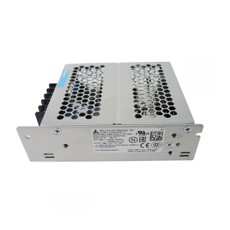
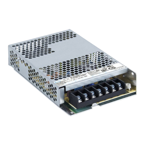
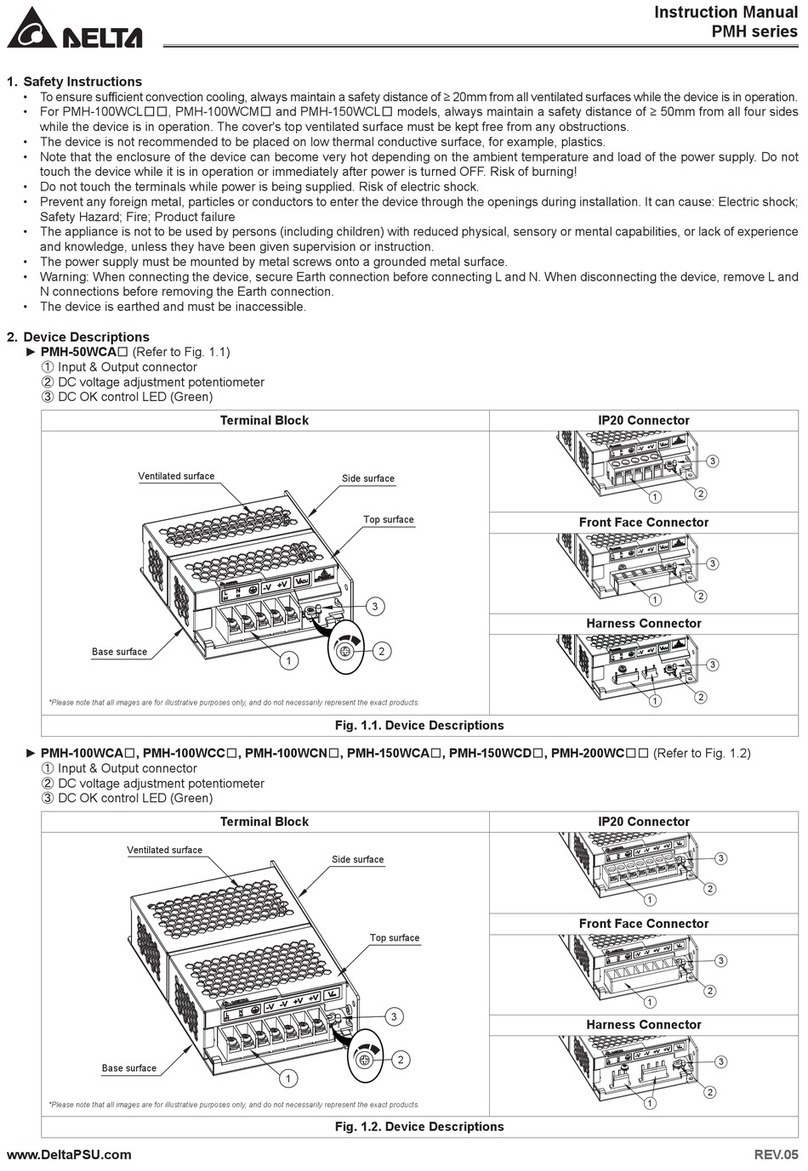
Delta PMU-27V155WC A Series User manual

Instruction Manual PMU-27V155WC□A
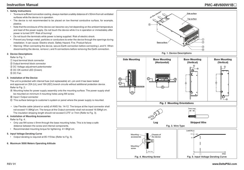
1. Safety Instructions
• MustselectcorrectACinputvoltagerangethroughselectableswitchbeforeturningon(Referto
Fig.1,⑥).
• To ensure sufcient convection cooling, always maintain a safety distance of ≥ 20mm from all
ventilatedsurfaceswhilethedeviceisinoperation.
• Thedevice isnot recommendedto beplaced onlow thermalconductive surface,for example,
plastics.
• Notethattheenclosureofthedevicecanbecomeveryhotdependingontheambienttemperature
andloadofthepowersupply.Donottouchthedevicewhileitisinoperationorimmediatelyafter
poweristurnedOFF.Riskofburning!
• Donottouchtheterminalswhilepowerisbeingsupplied.Riskofelectricshock.
• Preventanyforeignmetal,particlesorconductorstoenterthedevicethroughtheopeningsduring
installation.Itcancause:Electricshock;SafetyHazard;Fire;Productfailure
• Batteryneedtobeprotectedfromshortcircuitwhileinstallation&servicing.Dangerofexplosion.
• SignalcableshouldnotinteractwithACInput.
• Warning:Whenconnectingthedevice,secureEarthconnectionbeforeconnectingLandN.When
disconnectingthedevice,removeLandNconnectionsbeforeremovingtheEarthconnection.
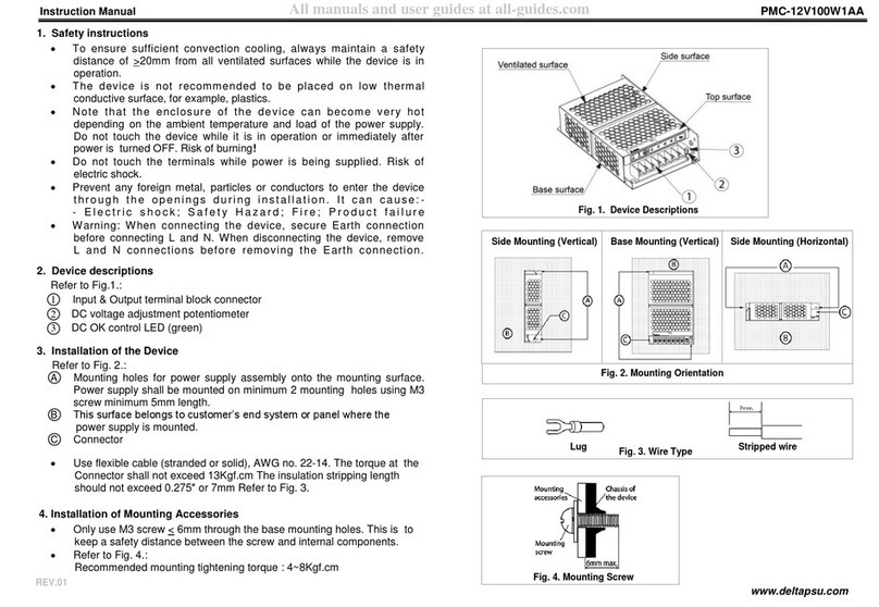
2. Device Descriptions
RefertoFig.1.:
䐟Input&Outputterminalblockconnector
䐠DCvoltageadjustmentpotentiometer(24V-28V)
䐡Green LED ON = DC OK (Normal operation through mains supply or through battery when
operatinginbufferingmode)
մRedLEDON=Batteryreversepolarity
յBatterychargingcurrentadjustmentpotentiometer(FactorySetting:1A)
Max charging current shall not exceed 1.5A (Refer to Fig. 1, ⑤).
նACselectableswitch
䷻Signalconnector-JST:XHP-4(forPMU-27V155WCCAonly)
3. Installation of the Device
RefertoFig.2.:
䑵Mountingholesforthepowersupplyassemblyontothemountingsurface.Thepowersupplyshall
bemountedonminimum2mountingholesusingM3screwminimum5mmlength.
䑶Thissurfacebelongstocustomer’sendsystemorpanelwherethedeviceismounted.
䑷Connector
• Useexiblecable(strandedorsolid),AWGNo.16-14.
• ThetorqueattheConnectorshallnotexceed13Kgf.cm.Theinsulationstrippinglengthshouldnot
exceed0.275”or7mm(RefertoFig.3).
4. Battery Information
Battery Capacity 3.2AH-15AH
Battery Cut-off Voltage 20V±1V
Battery Low (Deep Discharge) Detection* 17V±1V
*Ifthebatteryisdeepdischarged,thepowersupplywillnotrecognizethebattery.
5. Installation of Mounting Accessories
RefertoFig.4.:
• OnlyuseM3screw≤2.5mmthroughthebasemountingholes.Thisistokeepasafetydistance
betweenthescrewandinternalcomponents.
• Recommendedmountingtighteningtorque:4~8Kgf.cm.
www.DeltaPSU.comREV.00
Fig. 1. Device Descriptions
Fig. 3. Wire Type Fig. 4. Mounting Screw
Lug Stripped wire
Mounting
accessories
Mounting
screw
Chassis of
the device
2.5mm
max.
7 mm
Side Mounting (Vertical) Base Mounting (Vertical) Side Mounting (Horizontal)
A
B
A
B
A
C
C
C
B
A
B
A
B
A
C
C
C
B
A
B
A
B
A
C
C
C
B
Fig. 2. Mounting Orientation
Base surface
Top surface
Ventilated surface
Side surface
12
3
5
4
6
PMU-27V155WCBA (no signal connector) PMU-27V155WCCA (with signal connector)
Base surface
Top surface
Ventilated surface
Side surface
12
5
6
7
3
4
7Signalconnector
JST:XHP-4
Pin No.
1
2
3
4
DCOK
LowBattery
GND
ACOK
Description
400mm.(Ref.)
PMU-27V155WC□A
www.DeltaPSU.comREV.00
1. 安全規範
• 通电前需选择正确的交流输入电压(依据图一⑥的位置)。
• 與通風表面保持至少20mm的安全距離,以確保對流冷卻充分。
• 本產品不適合擺放在低熱導體,例如:塑膠。
• 受環境溫度及產品負載的影響,本機外殼溫度會很高,因此在上電時或切斷電源後短時間內
不要觸摸本機,以免燙傷。
• 請勿在上電時觸摸連接端子,以防電擊危險。
• 安裝過程中,應避免金屬元件或金屬導體通過空隙或通風孔進入到產品內,否則會引起下列
狀況。-電擊;安全危害;火災;產品異常
• 當安裝和維修時,需要保護電池以避免短路進而防止發生爆炸的危險。
• 信號線不能與交流輸入線纏繞在一起,以免交互影響。
• 警告:在連接產品電源供應時,產品必須先接地然後才接L和N。當要解開電源供應時,必須
先把L和N解開然後才把接地解開。
2. 產品外觀介紹
依據圖一:
䐟輸入/輸出連接端子
䐠直流電壓調節電位器(24V-28V)
䐡綠燈亮=DCOK(通過主電源在正常操作中或利用電池在緩沖模式中操作)
մ紅燈亮=電池極性反接
յ電池充電電流可調電位器(出廠設定:1A)
充電最大電流不能超過

1.5A
(依據圖一⑤的位置)。
ն交流輸入切換開關
䷻信號連接器-JST:XHP-4(只有PMU-27V155WCCA)
3. 產品固定方式
依據圖二:
䑵在把產品安裝在固定表面時,將螺絲鎖入此固定孔。產品應該用長度至少5mm的M3螺絲
鎖入至少兩個固定孔。
䑶此固定表面為客戶系統表面。
䑷輸入/輸出連接端子。
• 電線的設計可使用多股或實心,AWGNo.16-14。
• 扭矩不應該超過13Kgf.cm。剝線的長度不應該超過0.275″或者7mm(依據圖三)。
4. 电池信息
電池容量 3.2AH-15AH
電池截止電壓 20V±1V
電池低電壓檢測(深度放電)*17V±1V
*在電池深度放電後,開關電源將無法識別電池。
5. 配件組合安裝
依據圖四:
• 在把配件裝上產品時,請使用伸入產品長度不超過 2.5mm 的 M3 螺絲鎖入產品底面的固定
孔。這是為了確保螺絲和內部元件間有足夠的絕緣距離。
• 建議配件固定螺絲扭矩為4~8Kgf.cm。
1. 安全规范
• 通电前需选择正确的交流输入电压(依据图一⑥的位置)。
• 与通风表面保持至少20mm的安全距离,以确保对流冷却充分。
• 本产品不适合摆放在低热导体,例如:塑胶。
• 受环境温度及产品负载的影响,本机外壳温度会很高,因此在上电时或切断电源后短时间内
不要触摸本机,以免烫伤。
• 请勿在上电时触摸连接端子,以防电击危险。
• 安装过程中,应避免金属元件或金属导体通过空隙或通风孔进入到产品内,否则会引起下列
状况。-电击;安全危害;火灾;产品异常
• 当安装和维修时,需要保护电池以避免短路进而防止发生爆炸的危险。
• 信号线不能与交流输入线缠绕在一起,以免交互影响。
• 警告:在连接产品电源供应时,产品必须先接地然后才接L和N。当要解开电源供应时,必须
先把L和N解开然后才把接地解开。
2. 产品外观介绍
依据图一:
䐟输入/输出连接端子
䐠直流电压调节电位器(24V-28V)
䐡绿灯亮=DCOK(通过主电源在正常操作中或利用电池在缓冲模式中操作)
մ红灯亮=电池极性反接
յ电池充电电流可调电位器(出厂设定:1A)
充电最大电流不能超过

1.5A(依据图一⑤的位置)。
ն交流输入切换开关
䷻信号连接器-JST:XHP-4(只有PMU-27V155WCCA)
3. 产品固定方式
依据图二:
䑵在把产品安装在固定表面时,将螺丝锁入此固定孔。产品应该用长度至少 5mm 的 M3 螺丝
锁入至少两个固定孔。
䑶此固定表面为客户系统表面。
䑷输入/输出连接端子。
• 电线的设计可使用多股或实心,AWGNo.16-14。
• 扭矩不应该超过13Kgf.cm。剥线的长度不应该超过0.275″或者7mm(依据图三)。
4. 电池信息
电池容量 3.2AH-15AH
电池截止电压 20V±1V
电池低电压检测(深度放电)*17V±1V
*在电池深度放电后,开关电源将无法识别电池。
5. 配件组合安装
依据图四:
• 在把配件装上产品时,请使用伸入产品长度不超过 2.5mm 的 M3 螺丝锁入产品底面的固定
孔。这是为了确保螺丝和内部元件间有足够的绝缘距离。
• 建议配件固定螺丝扭矩为4~8Kgf.cm。
使用说明书使用說明書
Instruction Manual PMU-27V155WL□A
1. Safety Instructions
• MustselectcorrectACinputvoltage rangethroughselectable switchbeforeturning on(Referto
Fig.1,⑥).
• To ensure sufcient convection cooling, always maintain a safety distance of ≥ 20mm from all
ventilatedsurfaceswhilethedeviceisinoperation.
• Forsafetyreasons,pleaseensurethemounteddeviceiskeptat≥7mmsafetydistanceatthetop
andleftsidefromothercomponentsandequipments(RefertoFig.2).
• The device is not recommended to be placed on low thermal conductive surface, for example,
plastics.
• Notethattheenclosureofthedevicecanbecomeveryhotdependingontheambienttemperature
andloadofthepowersupply.Donottouchthedevicewhileitisinoperationorimmediatelyafter
poweristurnedOFF.Riskofburning!
• Donottouchtheterminalswhilepowerisbeingsupplied.Riskofelectricshock.
• Preventanyforeignmetal,particlesorconductorstoenterthedevicethroughtheopeningsduring
installation.Itcancause:Electricshock;SafetyHazard;Fire;Productfailure
• Batteryneedtobeprotectedfromshortcircuitwhileinstallation&servicing.Dangerofexplosion.
• SignalcableshouldnotinteractwithACInput.
• Warning:Whenconnectingthedevice,secureEarthconnectionbeforeconnectingLandN.When
disconnectingthedevice,removeLandNconnectionsbeforeremovingtheEarthconnection.
2. Device Descriptions
RefertoFig.1.:
䐟Input&Outputterminalblockconnector
䐠DCvoltageadjustmentpotentiometer(24V-28V)
䐡Green LED ON = DC OK (Normal operation through mains supply or through battery when
operatinginbufferingmode)
մRedLEDON=Batteryreversepolarity
յBatterychargingcurrentadjustmentpotentiometer(FactorySetting:1A)
Max charging current shall not exceed 1.2A (Refer to Fig. 1, ⑤).
նACselectableswitch
䷻Signalconnector-JST:XHP-4(forPMU-27V155WLCAonly)
3. Installation of the Device
RefertoFig.3.:
䑵Mountingholesforthepowersupplyassemblyontothemountingsurface.Thepowersupplyshall
bemountedonminimum2mountingholesusingM3screwminimum5mmlength.
䑶Thissurfacebelongstocustomer’sendsystemorpanelwherethedeviceismounted.
䑷Connector
• Useexiblecable(strandedorsolid),AWGNo.16-14.
• ThetorqueattheConnectorshallnotexceed13Kgf.cm.Theinsulationstrippinglengthshouldnot
exceed0.275”or7mm(RefertoFig.4).
4. Battery Information
Battery Capacity 3.2AH-15AH
Battery Cut-off Voltage 20V±1V
Battery Low (Deep Discharge) Detection* 17V±1V
*Ifthebatteryisdeepdischarged,thepowersupplywillnotrecognizethebattery.
5. Installation of Mounting Accessories
RefertoFig.5.:
• OnlyuseM3screw≤2.5mmthroughthebasemountingholes.Thisistokeepasafetydistance
betweenthescrewandinternalcomponents.
• Recommendedmountingtighteningtorque:4~8Kgf.cm.
www.DeltaPSU.comREV.00
Fig. 1. Device Descriptions
Fig. 4. Wire Type Fig. 5. Mounting Screw
Lug Stripped wire
Mounting
accessories
Mounting
screw
Chassis of
the device
2.5mm
max.
7 mm
Side Mounting (Vertical) Base Mounting (Vertical) Side Mounting (Horizontal)
A
B
C
A
C
BA
B
C
A
B
C
A
C
B
A
B
C
A
B
C
A
C
B
A
B
C
Fig. 3. Mounting Orientation
Base surface
Side surface
127
3
5
4
6
Fig. 2. Assembly Reference
≥ 7mm
CN1
PSU
CN1
≥ 7mm
PSU
TOP SIDE
LEFT SIDE
LEFT
TOP
Signalconnector-JST:XHP-4
(forPMU-27V155WLCAonly)
7
Pin No.
1
2
3
4
DCOK
LowBattery
GND
ACOK
Description
400mm.(Ref.)
PMU-27V155WL□A
www.DeltaPSU.comREV.00
1. 安全規範
• 通电前需选择正确的交流输入电压(依据图一⑥的位置)。
• 與通風表面保持至少20mm的安全距離,以確保對流冷卻充分。
• 基於安全考量,上方與靠近左側的元器件和設備必須與本產品保持至少7mm的安全距離
(請參考圖二)。
• 本產品不適合擺放在低熱導體,例如:塑膠。
• 受環境溫度及產品負載的影響,本機外殼溫度會很高,因此在上電時或切斷電源後短時間內
不要觸摸本機,以免燙傷。
• 請勿在上電時觸摸連接端子,以防電擊危險。
• 安裝過程中,應避免金屬元件或金屬導體通過空隙或通風孔進入到產品內,否則會引起下列
狀況。-電擊;安全危害;火災;產品異常
• 當安裝和維修時,需要保護電池以避免短路進而防止發生爆炸的危險。
• 信號線不能與交流輸入線纏繞在一起,以免交互影響。
• 警告:在連接產品電源供應時,產品必須先接地然後才接L和N。當要解開電源供應時,必須
先把L和N解開然後才把接地解開。
2. 產品外觀介紹
依據圖一:
䐟輸入/輸出連接端子
䐠直流電壓調節電位器(24V-28V)
䐡綠燈亮=DCOK(通過主電源在正常操作中或利用電池在緩沖模式中操作)
մ紅燈亮=電池極性反接
յ電池充電電流可調電位器(出廠設定:1A)
充電最大電流不能超過

1.2A
(依據圖一⑤的位置)。
ն交流輸入切換開關
䷻信號連接器-JST:XHP-4(只有PMU-27V155WLCA)
3. 產品固定方式
依據圖三:
䑵在把產品安裝在固定表面時,將螺絲鎖入此固定孔。產品應該用長度至少5mm的M3螺絲
鎖入至少兩個固定孔。
䑶此固定表面為客戶系統表面。
䑷輸入/輸出連接端子。
• 電線的設計可使用多股或實心,AWGNo.16-14。
• 扭矩不應該超過13Kgf.cm。剝線的長度不應該超過0.275″或者7mm(依據圖四)。
4. 电池信息
電池容量 3.2AH-15AH
電池截止電壓 20V±1V
電池低電壓檢測(深度放電)*17V±1V
*在電池深度放電後,開關電源將無法識別電池。
5. 配件組合安裝
依據圖五:
• 在把配件裝上產品時,請使用伸入產品長度不超過 2.5mm 的 M3 螺絲鎖入產品底面的固定
孔。這是為了確保螺絲和內部元件間有足夠的絕緣距離。
• 建議配件固定螺絲扭矩為4~8Kgf.cm。
1. 安全规范
• 通电前需选择正确的交流输入电压(依据图一⑥的位置)。
• 与通风表面保持至少20mm的安全距离,以确保对流冷却充分。
• 基于安全考量,上方与靠近左侧的元器件和设备必须与本产品保持至少7mm的安全距离
(请参考图二)。
• 本产品不适合摆放在低热导体,例如:塑胶。
• 受环境温度及产品负载的影响,本机外壳温度会很高,因此在上电时或切断电源后短时间内
不要触摸本机,以免烫伤。
• 请勿在上电时触摸连接端子,以防电击危险。
• 安装过程中,应避免金属元件或金属导体通过空隙或通风孔进入到产品内,否则会引起下列
状况。-电击;安全危害;火灾;产品异常
• 当安装和维修时,需要保护电池以避免短路进而防止发生爆炸的危险。
• 信号线不能与交流输入线缠绕在一起,以免交互影响。
• 警告:在连接产品电源供应时,产品必须先接地然后才接L和N。当要解开电源供应时,必须
先把L和N解开然后才把接地解开。
2. 产品外观介绍
依据图一:
䐟输入/输出连接端子
䐠直流电压调节电位器(24V-28V)
䐡绿灯亮=DCOK(通过主电源在正常操作中或利用电池在缓冲模式中操作)
մ红灯亮=电池极性反接
յ电池充电电流可调电位器(出厂设定:1A)
充电最大电流不能超过

1.2A(依据图一⑤的位置)。
ն交流输入切换开关
䷻信号连接器-JST:XHP-4(只有PMU-27V155WLCA)
3. 产品固定方式
依据图三:
䑵在把产品安装在固定表面时,将螺丝锁入此固定孔。产品应该用长度至少 5mm 的 M3 螺丝
锁入至少两个固定孔。
䑶此固定表面为客户系统表面。
䑷输入/输出连接端子。
• 电线的设计可使用多股或实心,AWGNo.16-14。
• 扭矩不应该超过13Kgf.cm。剥线的长度不应该超过0.275″或者7mm(依据图四)。
4. 电池信息
电池容量 3.2AH-15AH
电池截止电压 20V±1V
电池低电压检测(深度放电)*17V±1V
*在电池深度放电后,开关电源将无法识别电池。
5. 配件组合安装
依据图五:
• 在把配件装上产品时,请使用伸入产品长度不超过 2.5mm 的 M3 螺丝锁入产品底面的固定
孔。这是为了确保螺丝和内部元件间有足够的绝缘距离。
• 建议配件固定螺丝扭矩为4~8Kgf.cm。
使用说明书使用說明書

This manual suits for next models

2

Other Delta Power Supply manuals

Delta PMC-48V600W1B Series User manual

Delta

Delta PMC-48V600W1B Series User manual

Delta PMU-27V155WC A Series User manual

Delta

Delta PMU-27V155WC A Series User manual

Delta GPS-1000D8 A A22 User manual

Delta

Delta GPS-1000D8 A A22 User manual

Delta LYTE DRL-24V480W1A Series Instruction Manual

Delta

Delta LYTE DRL-24V480W1A Series Instruction Manual

Delta GPS-650JB E A22 User manual

Delta

Delta GPS-650JB E A22 User manual

Delta D750 User manual

Delta

Delta D750 User manual

Delta PMC-05V015W1A Series User manual

Delta

Delta PMC-05V015W1A Series User manual

Delta HDS 3000 User manual

Delta

Delta HDS 3000 User manual

Delta MCS-600 Series Instruction manual

Delta

Delta MCS-600 Series Instruction manual

Delta DRP024V480W1B Series Instruction Manual

Delta

Delta DRP024V480W1B Series Instruction Manual

Delta DPS-0220 User manual

Delta

Delta DPS-0220 User manual

Delta CliQ DRP024V120W1AA Quick start guide

Delta

Delta CliQ DRP024V120W1AA Quick start guide

Delta sync 24V 100W Series Instruction Manual

Delta

Delta sync 24V 100W Series Instruction Manual

Delta PMR V320WD Series User manual

Delta

Delta PMR V320WD Series User manual

Delta PMC-24V150W1A Series User manual

Delta

Delta PMC-24V150W1A Series User manual

Delta PMC-12V035W1AA User manual

Delta

Delta PMC-12V035W1AA User manual

Delta CliQ II DRP024V060W1N Series Instruction Manual

Delta

Delta CliQ II DRP024V060W1N Series Instruction Manual

Delta ZBF-12V/3A User manual

Delta

Delta ZBF-12V/3A User manual

Delta PMC-05V050W1AA User manual

Delta

Delta PMC-05V050W1AA User manual

Delta PMC-24V075W1AA User manual

Delta

Delta PMC-24V075W1AA User manual

Delta PMC Series User manual

Delta

Delta PMC Series User manual

Delta GPS-550LB E A22 User manual

Delta

Delta GPS-550LB E A22 User manual

Delta DRP024V240W3BA Quick start guide

Delta

Delta DRP024V240W3BA Quick start guide

Delta CliQ DRP024V060W1AA Instruction Manual

Delta

Delta CliQ DRP024V060W1AA Instruction Manual

Popular Power Supply manuals by other brands

Perle IDPS-24-40-XT Hardware installation guide

Perle

Perle IDPS-24-40-XT Hardware installation guide

Russound V-PS-2 product manual

Russound

Russound V-PS-2 product manual

Rutland ESM401 installation guide

Rutland

Rutland ESM401 installation guide

Rebelcell Outdoorbox ThrustMe user manual

Rebelcell

Rebelcell Outdoorbox ThrustMe user manual

Velleman LABPS3003SMU user manual

Velleman

Velleman LABPS3003SMU user manual

Puls QS10.481 installation manual

Puls

Puls QS10.481 installation manual

Genki GK-2000 user manual

Genki

Genki GK-2000 user manual

Apevia Prestige Series user manual

Apevia

Apevia Prestige Series user manual

Manhattan 168205 user manual

Manhattan

Manhattan 168205 user manual

Voltech DC1000A User manal

Voltech

Voltech DC1000A User manal

Velleman PS603 user manual

Velleman

Velleman PS603 user manual

M2TECH EVO SUPPLY user manual

M2TECH

M2TECH EVO SUPPLY user manual

Huawei UPS2000 Series Development guide

Huawei

Huawei UPS2000 Series Development guide

Invitrogen PowerEase PSHV00 user guide

Invitrogen

Invitrogen PowerEase PSHV00 user guide

ELC ALR3203 quick start guide

ELC

ELC ALR3203 quick start guide

Kikusui PCR500MA Interface manual

Kikusui

Kikusui PCR500MA Interface manual

Denver MCA-110 instruction manual

Denver

Denver MCA-110 instruction manual

Nordelettronica NE324 TVDL instruction manual

Nordelettronica

Nordelettronica NE324 TVDL instruction manual

manuals.online logo
manuals.online logoBrands
  • About & Mission
  • Contact us
  • Privacy Policy
  • Terms and Conditions

Copyright 2025 Manuals.Online. All Rights Reserved.