PJH-36V300WB☐
www.DeltaPSU.comREV.00
Instruction Manual
1. Safety Instructions
2. Device Description
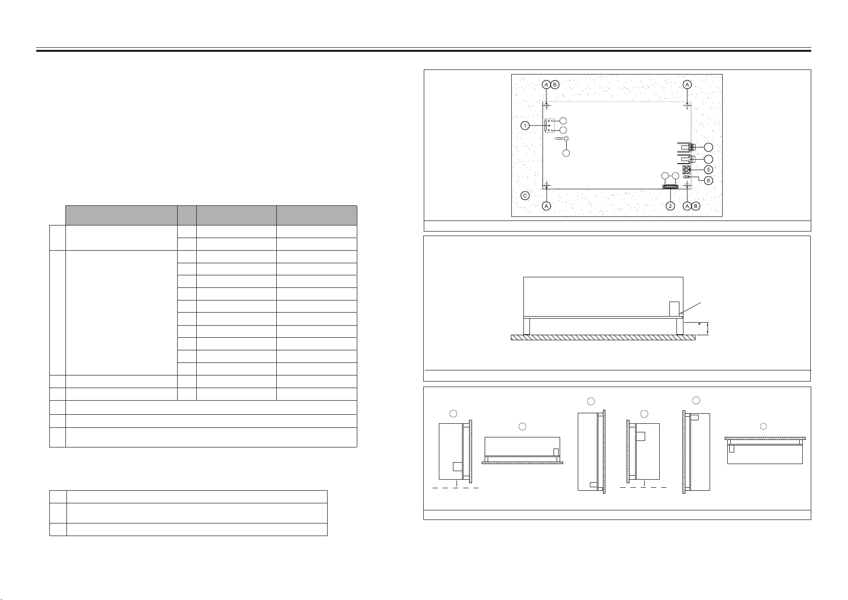
Refer ot Fig .1.:
• The device is not recommended to be placed on low thermal conductive surface, for example, plastics.
• For safety reason, please ensure the mounted device is kept at ≥ 8mm safety distance for D1 from other components
and equipments. Please insert an insulation sheet between the system and product, if the safety distance is < 8mm for D2
(Refer to Fig. 2.1)
• Installation of forced air, to ensure sucient air ow, always maintain a distance and air ow direction
as recommended in Fig. 4. while the device is in operation.
• Note that the device can become very hot depending on the ambient temperature and load of the power supply.
Do not touch the device while it is in operation or immediately after power is turned OFF. Risk of burning!
• Do not touch the terminals while power is being supplied. Risk of electric shock.
• Prevent any foreign metal, particles or conductors to enter the device through the openings during installation. It can cause:
Electric shock; Safety Hazard; Fire; Product failure.
• For Protection against shock to Class I with PE (protection earth) and Class II with or without FG (functional ground) product,
the two mounting holes (marked Ⓑ in Fig. 1) need to be connected together to the system’s protective earth or functional ground.
Pollution degree and EMC performance with dierent connections please refer to product datasheet.
• Warning: The power supply must be mounted by metal screws onto a grounded metal surface. It is highly recommended that
the Earth terminal on the connector be connected to the grounded metal surface.
A
B
C
D
CN1
CN1
CN1
CN1
E
F
CN1
CN1
D2* D2*
Fig. 1. Device Description
Fig. 2. Assembly Reference
Fig. 3. Mounting Orientations
D1* ≥ 8mm
D2* ≥ 30mm
3. Installation of the Device
The unit is protected with internal fuse (not replaceable) at L pin and it has been tested and approved on
20A (UL) and 16A (IEC) branch circuits without additional protection device.
ⒶMounting holes for the power supply.1)
ⒷMounting holes should be connected to the system’s protective earthing (PE) for Class I or
fuctional ground (FG) for Class II.1)
ⒸThis surface belongs to customer’s end system or panel where the power supply is mounted.
1) Note: 4 × Ø3.5 Mounting Holes; Ø5.5 Max Dimension of Screw Head. Recommended mounting torque for tightening: 4-8Kgf.cm.
Refer to Fig .1.:
Description PIN
No.
Function
► PJH-36V300WBB☐
Function
► PJH-36V300WBC☐
①Input connector (CN1) 1Neutral (N) Neutral (N)
2 Line (L) Line (L)
②Control and Vsb Connector (CN101) 1Netutral (N) Netutral (N)
2 5VSB 12VSB
3 GND GND
45VSB 12VSB
5 GND GND
6Remote On/O Remote On/O
7GND GND
8 Power Good Power Good
9Remote Sense of V1(-) Remote Sense of V1(-)
10 Remote Sense of V1(+) Remote Sense of V1(+)
③Output Connector (CN103) 1GND GND
④Output Connector (CN102) 1V1(+) V1(+)
⑤DC voltage adjustment potentiometer
⑥DC OK control LED (Green)
⑦Internal fuse is a time lag type, rated 5A / 250Vac.
Walter: Type ICP Conquer: Type PTU TR


