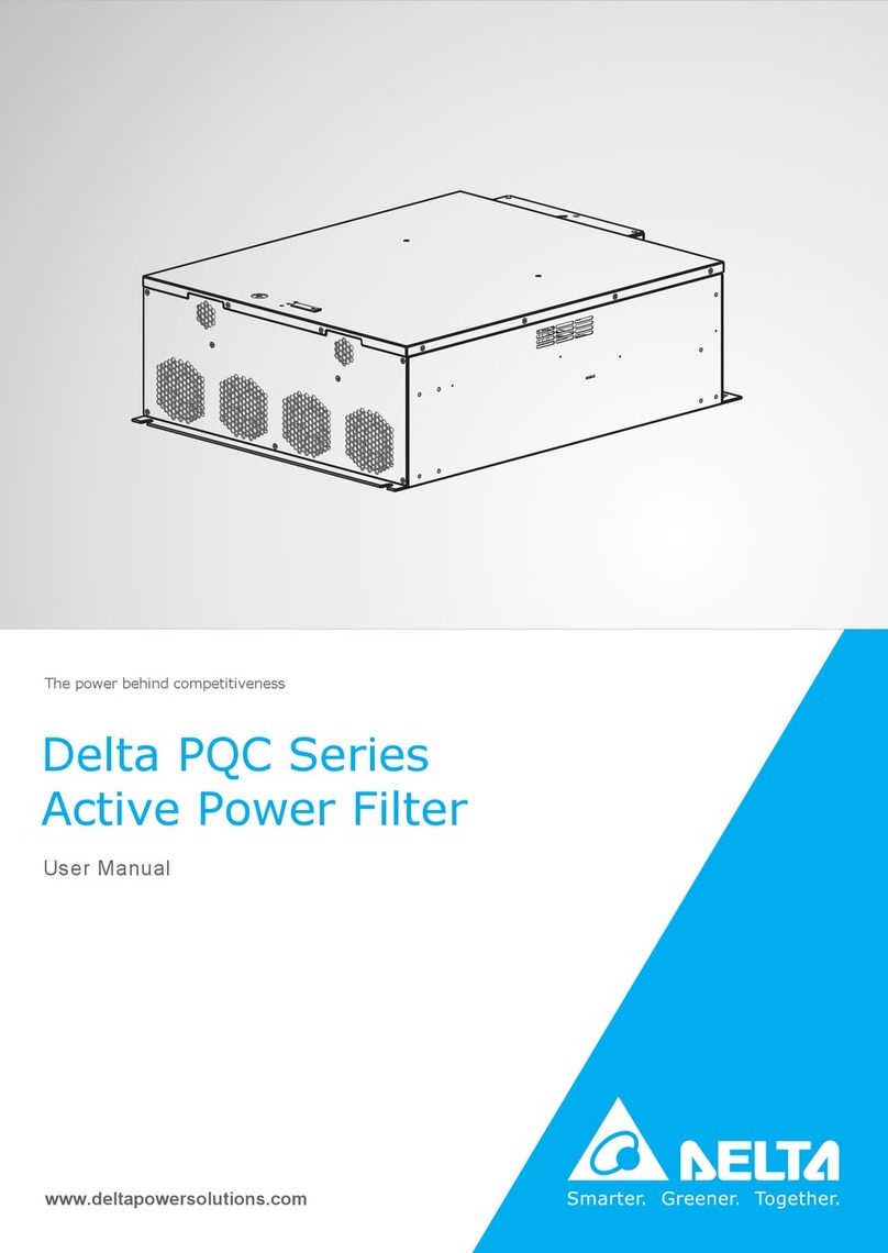
Delta PQC Series User manual

The power behind competitiveness
www.deltapowersolutions.com
Delta PQC Series
Fixed Type Active Power Filter
User Manual

II
PQC Series Active Power Filter
Save This Manual
This manual contains important instructions and warnings that you should follow
during the installation, operation, storage and maintenance of this product. Failure
to heed these instructions and warnings will void the warranty.
Copyright © 2017 by Delta Electronics Inc. All Rights Reserved. All rights of this User Manual
(“Manual”), including but not limited to the contents, information, and figures are solely owned and
reserved by Delta Electronics Inc. (“Delta”). The Manual can only be applied to the operation or the
use of this product. Any disposition, duplication, dissemination, reproduction, modication, translation,
extraction, or usage of this Manual in whole or in part is prohibited without the prior written permission
of Delta. Given that Delta will continuously improve and develop the product, changes may be made
to the information in this Manual at any time without obligation to notify any person of such revision
or changes. Delta will make all possible efforts to secure the accuracy and the integrity of this
Manual. Delta disclaims any kinds or forms of warranty, guarantee, or undertaking, either expressly
or implicitly, including but not limited to the completeness, faultlessness, accuracy, non-infringement,
merchantability or tness for a particular purpose of the Manual.

Table of Contents
III
Table of Contents
Chapter 1 : Important Safety Instructions ------------------------------------------1
1.1. Safety Precautions ------------------------------------------------------------------ 1
1.2. Wiring Warnings --------------------------------------------------------------------- 1
1.3. Usage Warnings --------------------------------------------------------------------- 2
1.4. Storage Precautions ---------------------------------------------------------------- 2
1.5. Symbols-------------------------------------------------------------------------------- 2
Chapter 2 : Introduction ------------------------------------------------------------------3
2.1 Product Introduction ---------------------------------------------------------------- 3
2.2 APF Series Product Category---------------------------------------------------- 4
2.3 Functions & Features--------------------------------------------------------------- 6
2.4 Mechanism & Appearance -------------------------------------------------------- 7
2.4.1 LCM (Liquid Crystal Monitor)----------------------------------------- 7
2.4.2 Appearance & Dimensions of the Power Module --------------- 8
2.5. Package Inspection ----------------------------------------------------------------10
Chapter 3 : Installation and Wiring-------------------------------------------------- 12
3.1 Pre-installation Conrmation ----------------------------------------------------12
3.2 Installation Environment ----------------------------------------------------------12
3.3 Fixed-type Module -----------------------------------------------------------------14
3.3.1 Fixed-type Module Structure ----------------------------------------14
3.3.2 LCM Structure-----------------------------------------------------------18
3.3.3 Wiring of the Fixed-type Module------------------------------------19
3.4 CT Installation & Wiring for Current Detection of Harmonic Source---26
3.4.1 CT Selection Precautions --------------------------------------------26
3.4.2 Basic CT Installation & Wiring --------------------------------------26
Chapter 4 : APF Operation Procedure --------------------------------------------- 28
4.1 Checks Before Start-up -----------------------------------------------------------28
4.2 Start-up Procedures ---------------------------------------------------------------29
Chapter 5 : LCM Display and Settings --------------------------------------------- 30
5.1 Description of LCM Display ------------------------------------------------------30
5.2 LCM Display Hierarchy -----------------------------------------------------------31

IV
PQC Series Active Power Filter
Chapter 6 : Maintenance --------------------------------------------------------------- 32
Chapter 7 : Troubleshooting ---------------------------------------------------------- 33
Chapter 8 : Warranty --------------------------------------------------------------------- 34

1
Chapter 1 Important Safety Instructions
Chapter 1 : Important Safety Instructions
1.1. Safety Precautions
yyThe active power lter (‘APF’) is designed for industrial applications. It shall be connected
with a power grid system and in parallel with harmonic sources (i.e. nonlinear loads) as a
means to control harmonics.
yyThe APF shall not be exposed to rain or wet conditions, and shall be away from any am-
mable uid, gas or explosives.
yyAdequate space shall be left in the front and at the back of the APF for well ventilation
and convenient maintenance.
yyTo minimize re and electric shock hazards, installation must be conducted by the quali-
ed personnel in a controllable working environment.
yyTo minimize electric shock hazards, all maintenance work must be carried out by the
qualied technician, and be sure to cut off all power supply before maintenance.
yyHigh voltage hazards! It takes over 15 minutes for the DC capacitor to discharge. Please
make sure the device has discharged completely before carrying out any operation.
yyTo minimize electric shock hazards, please read this Manual carefully before switching
the power on, and keep this Manual properly for permanent reference.
yyWhen the APF is used in IT applications, please install an insulation resistance detection
device so that the alarm will go off when protection earth fault is detected.
1.2. Wiring Warnings
yyTo prevent a possible risk of current leakage, the APF shall be earthed properly.
yyWith regard to wiring, the compensation capacity and the current-carrying capacities of
cables shall be taken into account.
yyThe incoming lines of the APF shall be connected with appropriate protective devices. It
is recommended to provide every module with an over-current protective device with a
third-party certication. Besides, take the installation positions of auxiliary equipment into
consideration and choose the protective devices with adequate breaking capacity.
yy The capacity of the protective devices shall t that of the APF.
yyTo prevent scaling caused by high temperature, after the power is cut off, the operating
switch shall be allowed to cool down before being operated again.
yyThe three-phase, four-wire APF is applicable to the power grid system with neutral
grounding.

2
PQC Series Active Power Filter
1.3. Usage Warnings
yySince the APF is used for harmonic compensation of the power grid, the capacity selec-
tion of the APF shall be subject to the harmonic content to avoid poor compensation due
to insufcient capacity.
yySince the APF is used for harmonic control, it shall be connected to harmonic current from
an external source for CT testing (CT: Current transformer).
yyTo guarantee sound reliability and avoid overheating, do not block or cover the air inlet
and outlet.
yyThe working temperature range of the APF is -10°C - 50°C, beyond which the APF will not
work.
1.4. Storage Precautions
yyPlease use the original packing material to protect the APF in order to avoid damage by
rodents.
yyIf the customer will not install the APF immediately after receiving the equipment, please
be sure to store the APF in a dry and ventilated indoor place, which shall be maintained
between -40°C and 70°C with relative humidity no higher than 95%.
1.5. Symbols
Item Symbol Meaning
1 R Phase R of three-phase power supply
2 S Phase S of three-phase power supply
3 T Phase T of three-phase power supply
4 N Neutral line
5Main grounding terminal
6E.P.O key
7 XT Terminal board
8 QF Circuit breaker
9 XK Auxiliary switch

3
Chapter 2 Introduction
Chapter 2 : Introduction
2.1 Product Introduction
The active power lter ('APF'), a harmonic compensator for the three-phase power grid, is
applied to the harmonic control of the power grid. Features of the device are shown as below:
yyCompensates a wide range of harmonic frequency and any randomly specied harmonic.
yyRapid dynamic responses, stable parameters and good harmonic compensation results.
yyHigh efciency and low thermal loss.
yyModular design offers a variety of coordination with various compensation capacities.
yyThe system adopts an advanced 3-level structure and consists of digital signal proces-
sors (DSP),large programmable controllers and high power electronic devices, which has
excellent performance and superior reliability.
yyProvides perfect system protection functions.
yySupports remote power on/ off functions via computer monitoring.
Please see Figure 2-1 for the APF system block diagram. The APF system is composed of a
xed-type module, a LCM (Liquid Crystal Monitor) and a system cabinet. The external CT is
used for the detection of load current in the module and extraction of harmonic components,
based on which, the main power controller controls the main power circuit to generate reverse
harmonic current; in this way, the load-carrying harmonic components are counteracted.
Each standard system cabinet can be connected to up to 7 modules in parallel. As for the
non-standard cabinet, the quantity of the modules installed inside could be varied according to
different design. Please note that the xed-type module and the LCM are packed separately. If
you would like to buy both of them, you should purchase them separately. The LCM monitors
and controls the xed-type module online. If monitoring function is not required, there is no
need to buy and install the LCM.

4
PQC Series Active Power Filter
Non-linear load
Single-phase load
Three-phase load
CT
Harmonic
detection of
load current
Main
power
circuit
LCM
Optional Module
APF System
Power grid
Main
power
control
Module
Main
power
circuit
Main
power
control
Harmonic
detection of
load current
(Figure 2-1: APF System Block Diagram)
2.2 APF Series Product Category
The APF series product includes the xed-type module and the LCM. Table 2-1 lists the xed-
type module’s model, capacity and wiring system, as well as the LCM’s model information.
Table 2-1: PQC Series APF_ Fixed-type Module & LCM Specications
Product Model Capacity Wiring System
Fixed-type
Module
PQCA-400-50-50FM3 (4) 50A/ 400V Three-phase three-wire/
four-wire
PQCA-400-75-75FM3 (4) 75A/ 400V Three-phase three-wire/
four-wire
PQCA-400-100-100FM3 (4) 100A/ 400V Three-phase three-wire/
four-wire
PQCA-690-100-100FM3 100A/ 690V Three-phase three-wire
LCM PQCMA-LCM N/A N/A
yyFixed-type Module
The fixed-type module is a terminal-wiring design, which can be easily installed into
a standard or non-standard system cabinet. Subject to the customer's requirement
of equipment capacity, the modules can be easily connected in parallel for capacity
expansion.

5
Chapter 2 Introduction
The module is available in two wiring modes, i.e. 3P3W and 3P4W, and is available in
three specications in terms of the output current, i.e. 50A, 75A and 100A. The 3P4W
module shall be connected to the neutral line, and it is able to compensate the current
of neutral line, including zero sequence fundamental current and 3rd harmonic current;
however, for the 3P3W module, it is unnecessary to connect the neutral line, and the
module is unable to compensate the current of neutral line, such as zero sequence
fundamental current and 3rd harmonic current, which are generated by single phase loads.
Figure 2-2 shows the xed-type module.
(Figure 2-2: External View of 75A Fixed-type Module)
yySystem Cabinet
The fixed-type module and LCM can be easily installed
in any standard or non-standard system cabinet that
has the correct size. For 3P4W application, the cabinet
must be connected to the neutral line and equipped with
3P4W modules; for 3P3W application, the cabinet is
unnecessary to be connected to the neutral line but must
be equipped with 3P3W modules. Figure 2-3 shows the
standard system cabinet.
The system capacity depends on the specifications &
quantity of the modules installed in the system cabinet.
Customers can depend on their capacity requirements to
determine the required quantity of the modules and the
required system cabinet, or consult the local distributor
about the required capacity.
(Figure 2-3: External View of
the Standard System Cabinet)

6
PQC Series Active Power Filter
2.3 Functions & Features
yyMultifunction: the APF can simultaneously realize the purposes of harmonic, reactive and
three-phase unbalance control.
yySuperior harmonic control effects: up to 97% harmonics of the system can be effectively
ltered.
yyExcellent compensation of reactive power: the device can realize rapid (ms-grade re-
sponse), precise (-0.99< PF< 0.99) and bi-directional (both capacitive and inductive com-
pensations) reactive power control.
yyOutstanding compensation of unbalanced three-phase: the device can realize correc-
tion for either active or reactive unbalance, and can eliminate the neutral current (for the
three-phase four-wire series only).
yyWide input voltage and frequency range, suitable for the applications with diesel genera-
tors and harsh power supply conditions.
Module Type Upper Limit Lower Limit
400V Module Line Voltage: 456V Line Voltage: 308V
690V Module Line Voltage: 880V Line Voltage: 432V
yy Low power loss (lower than 3% of rated device power) and actual efciency >97%.
yy Sound stability: the device acts as an innite impedance to the power grid system and
has no effect on the impedance of the power grid system; it is able to produce accurate
and awless output waveform, which has no effect on other equipment.
yy Simple and exible applications: thanks to the modular design, it can be easily embedded
into other cabinets to work with PDU.
yyWide capacity coverage: for a single system cabinet, its capacity depends on the quantity
of the installed modules; for parallel, its capacity is unlimited since there is no limited con-
nection for parallel system cabinets.
yyApplicable to all work conditions: the device is able to operate under high temperature up
to 50°C and salt spray corrosive conditions, can withstand grade-9 seismic intensity and
is compatible with the diesel engine generating system.
yyUser-friendly interface (in both Chinese and English): event log, automatic fault alarm,
alarm history and other parameter setting functions.
yyComplete functions: automatic self-checking start, settable soft start time, emergency
stop (E.P.O.), etc.

7
Chapter 2 Introduction
2.4 Mechanism & Appearance
2.4.1 LCM (Liquid Crystal Monitor)
ON/OFF
LCD
UP
ESC
ENTER
DOWN
NORMAL
STANDBY
FAULT
1
2
3
4
5
6
7
8
9
(Figure 2-4: LCM_ Front View)
Item Name Description
1NORMAL LED (green) Illuminates when the APF system is normal.
2STANDBY LED (yellow) Illuminates when the APF system is in standby status.
3FAULT LED (red) Illuminates when the APF system has abnormalities.
4LCD Display Displays both Chinese and English fonts.
5ON/ OFF Key Press and hold the key for 3 seconds to switch on/ off
the APF system.
6UP Key Press the key to move the menu items upward or to
increase the parameter setting value.
7ESC Key Press the key to return to the previous menu or to
save the parameter setting when exit.
8ENTER Key Press the key to go to the next page or to conrm the
parameter setting.
9DOWN Key Press the key to move the menu items downward or
to reduce the parameter setting value.

8
PQC Series Active Power Filter
DATABUS
RS232
1
2
(Figure 2-5: LCM_ Rear View)
Item Name Description
1DATABUS The communication interface between the LCM and the
xed-type module.
2RS232 The standard RS232 interface.
2.4.2 Appearance & Dimensions of the Fixed-type Module
(Figure 2-6: External View of the Fixed-type Module)

9
Chapter 2 Introduction
Rear View_690V Module
Rear View_400V Module
8
8
9
9
10
(Figure 2-7: Rear View of the Fixed-type Module)
Item Name Description
1DC Fans DC fans for heat dispersion.
2E.P.O Button Emergency power off button. Press it to shut down the device
and release it to switch on the device.
3LED Indicators
• Green (Normal): the module is functioning properly.
• Yellow (Standby): the module is in standby mode.
• Red (Fault): the module has abnormalities.
4DIP Switches Set the module ID and terminal resistance.
5
Databus
Communication
Ports
The ports are reserved for module settings, program update,
etc.
6Mechanical Lock
The module shall be plugged into the system cabinet and
push the lock rightward and tightly fix the lock; otherwise,
the fault alarm will be triggered and the module cannot work
properly.
7DC Fans DC fans for heat dispersion.

10
PQC Series Active Power Filter
Item Name Description
8Signal Transfer
Terminals Include communication terminals and CT terminals.
9Main Power
Input Terminals For main power input wiring (R/ S/ T/ N/ PE)
10
Auxiliary Power
Terminals For connecting 230V auxiliary power.
NOTE: Since the DATABUS port is provided with insulation isolation, it is safe to
touch it.
Table 2-2: PQC Series APF_ Fixed-type Module Dimensions & Weight
Model Dimensions (W×D×H) Weight
PQCA-400-50-50FM3 440 x 522 x 174 mm 40Kg
PQCA-400-50-50FM4 440 x 522 x 174 mm 40.5Kg
PQCA-400-75-75FM3 440 x 522 x 174 mm 41.5Kg
PQCA-400-75-75FM4 440 x 522 x 174 mm 42Kg
PQCA-400-100-100FM3 600 x 725 x 220 mm 63Kg
PQCA-400-100-100FM4 600 x 725 x 220 mm 65Kg
PQCA-690-100-100FM3 600 x 725 x 270 mm 78Kg
2.5. Package Inspection
NOTE: The APF includes the fixed-type module and the LCM, which are packed
separately. If you would like to buy both of them, you should separately purchase
them.
yyExterior
Some unpredictable situations might occur during transportation. It is recommended that
you inspect the exterior packaging after receiving the xed-type module and the LCM. If
you notice any damage, please contact your supplier.
yyInterior
1. Please check the rating labels of the fixed-type module and the LCM to see if the
products conform to your order.
2. Please check if any parts are damaged or loose.
3. Please check if the accessories are complete.

11
Chapter 2 Introduction
4. Please see the tables below for the standard accessories of the fixed-type and the
LCM.
5. If any damage is found, please contact your supplier.
6. To return goods, please use the original packing material to pack the fixed-type
module, the LCM and all standard accessories.
Table 2-3: Standard Accessories of the Fixed-type Module
No. Item Quantity
1User Manual 1 PC
2CT Wire 1 PC
3Communication Wire 1 PC
4AC Power Wire (for 690V 100A) 1 PC
5Screw M6*16L 4 PCS
Table 2-4: Standard Accessories of the LCM
No. Item Quantity
1LCM Connection Wire 1 PC
2Fastening Screw 4 PCS

12
PQC Series Active Power Filter
Chapter 3 : Installation and Wiring
The APF is applicable to many applications and can meet the particular installation requirements of
industrial sites, power distribution rooms and IT data centers. According to different work conditions
and environment requirements, the fixed-type module can be installed in a customized cabinet or
standard cabinet, and exible conguration and on-site capacity expansion can be realized based on
the current and subsequent capacity requirements.
3.1 Pre-installation Conrmation
Since the installation environment varies for different users, please be sure to read this
Manual carefully before installation. All installation, assembly and start-up work must be
carried out by the qualified professional personnel. If the work is to be carried out by the
customer, it shall be under the supervision of the qualied professional personnel. When a
forklift or similar lifting equipment is used to handle the device, make sure the lifting capacity
is sufcient. Please refer to Table 2-2 for the APF weight.
3.2 Installation Environment
1. The APF device can only be installed indoors. Do not install the device for outdoor use.
Be sure to consider the IP21 protection degree of the device while installing. For a higher
protection degree requirement, please contact the distributor.
2. The APF device shall not be installed in a place close to dust sources or subject to heavy
environmental pollution. Because the conductive dust will damage the device, make sure
the installation place is free of conductive dust.
3. Make sure the transport route and placement location are firm and big enough to
accommodate the APF system cabinet and forklift.
4. Since some noise can be generated during the operation of the APF, please take the noise
effects into account when choosing the installation position.
5. Keep the installation area clean. Please note that wiring routes must be hermetic to
prevent possible damage from rodents.
6. Make sure enough space is left in the installation place for future maintenance. For the
purpose of ventilation, avoid installing the APF against the wall. A space of 1500mm shall
be left in front of the device for front operation, maintenance and wiring.
7. Since some heat can be generated during the operation of the APF, please make sure the
cooling system of the installation environment is sufcient for heat dissipation, so that the
ambient temperature will not exceed the normal working temperature of the device.
8. The device is equipped with cooling fans, and is designed with air inlet in the front and air
outlet at the back; thus, it is recommended to leave at least a 500mm space both at the
front and the back for ventilation purpose. Figure 3-1 and Figure 3-2 illustrate the air inlet

13
Chapter 3 Installation and Wiring
& outlet schematic diagrams of the xed-type module and system cabinet.
9. Every module and system cabinet have their minimum vent ow requirements, which shall
be met to guarantee the normal cooling of the device. The air must be properly cooled and
treated to be free of conductive particles, heavy dust or hazardous gas before being fed
into the device through the air inlet.
10. The working temperature range of the APF is -10°C ~ 50°C, beyond which the APF will
not work.
11. Do not use the device in a place above an altitude of 1000m. If such a installation place
can not be avoided, please consider derating, or contact the distributor.
12. The xed-type module is recommended to be used in a customized system cabinet with at
least IP20 protection degree, in which, a distance of at least 10mm shall be kept between
the conductive metal cabinet parts and the live terminals of the module.
13.When the fixed-type module is used separately, the live terminals at the back of the
module must be provided with insulation caps. Please ask your supplier for insulation
caps.
Air outlet
Air inlet
(Figure 3-1: Air Inlet & Outlet Schematic
Diagram of the Fixed-type Module)
Air outlet
Air outlet
Air inlet
(Figure 3-2: Air Inlet & Outlet Schematic
Diagram of the System Cabinet)

14
PQC Series Active Power Filter
3.3 Fixed-type Module Structure & Wiring
3.3.1 Fixed-type Module Structure
(Figure 3-3: Side View of the Fixed-type Module)

15
Chapter 3 Installation and Wiring
yyFixed-type module installation dimensions diagram (three sizes, 400V below 75A (includ-
ing) module, 400V 100A module and 690V 100A module).
(Figure3-4: Installation Dimensions Diagram_ 400V below 75A (including) Module)
4-M6 screw hole (used for fastening the
module into the system cabinet)
465 mm
103 mm
9.5 mm
440 mm
490 mm
523.4 mm
174 mm
590.3 mm

16
PQC Series Active Power Filter
(Figure 3-5: Installation Dimensions Diagram_ 400V 100A Module)
4-M6 screw hole (used for fastening the
module into the system cabinet)
630 mm
14.5 mm
150 mm
652 mm
605 mm
811.7 mm
220 mm
Other manuals for PQC Series
3
This manual suits for next models
8
Table of contents
Other Delta Water Filtration System manuals
Popular Water Filtration System manuals by other brands

velda
velda Ultra Skimmer User instructions

CRH
CRH NRFS 04-04 Operation & maintenance manual

Antunes
Antunes UFL-420 Series owner's manual

Water Right
Water Right UltroWater Installation, operation & service manual

Campbell Hausfeld
Campbell Hausfeld MP513803 operating instructions

Pentair
Pentair AUTOTROL MAGNUM 742 Installer manual