Delta PQC Series User manual

Delta PQC Series
Active Power Filter
The power behind competitiveness
www.deltapowersolutions.com
User Manual

II
PQC Series Active Power Filter
Save This Manual
This manual contains important instructions and warnings that you should follow
during the installation, operation, storage and maintenance of this product. Failure
to heed these instructions and warnings will void the warranty.
Copyright © 2015 by Delta Electronics Inc. All Rights Reserved. All rights of this User Manual
(“Manual”), including but not limited to the contents, information, and figures are solely owned and
reserved by Delta Electronics Inc. (“Delta”). The Manual can only be applied to the operation or the
XVHRIWKLVSURGXFW$Q\GLVSRVLWLRQGXSOLFDWLRQGLVVHPLQDWLRQUHSURGXFWLRQPRGL¿FDWLRQWUDQVODWLRQ
extraction, or usage of this Manual in whole or in part is prohibited without the prior written permission
of Delta. Given that Delta will continuously improve and develop the product, changes may be made
to the information in this Manual at any time without obligation to notify any person of such revision
or changes. Delta will make all possible efforts to secure the accuracy and the integrity of this
Manual. Delta disclaims any kinds or forms of warranty, guarantee, or undertaking, either expressly
or implicitly, including but not limited to the completeness, faultlessness, accuracy, non-infringement,
PHUFKDQWDELOLW\RU¿WQHVVIRUDSDUWLFXODUSXUSRVHRIWKH0DQXDO

III
Table of Contents
Table of Contents
Chapter 1 : Important Safety Instructions ------------------------------------------1
1.1. Safety Precautions------------------------------------------------------------------ 1
1.2. Wiring Warnings --------------------------------------------------------------------- 1
1.3. Usage Warnings--------------------------------------------------------------------- 2
1.4. Storage Precautions---------------------------------------------------------------- 2
1.5. Symbols-------------------------------------------------------------------------------- 3
Chapter 2 : Introduction ------------------------------------------------------------------4
2.1 Product Introduction ---------------------------------------------------------------- 4
2.2 APF Series Product Category---------------------------------------------------- 5
2.3 Functions & Features--------------------------------------------------------------- 8
2.4 Mechanism & Appearance-------------------------------------------------------10
2.4.1 Appearance & Dimensions of the Cabinet System------------10
2.4.2 Appearance & Dimensions of the Embedded System--------11
2.4.3 Control Panel------------------------------------------------------------13
2.4.4 Appearance & Dimensions of the Power Module--------------14
2.5 Package Inspection----------------------------------------------------------------16
Chapter 3 : Installation and Wiring--------------------------------------------------18
3UHLQVWDOODWLRQ&RQ¿UPDWLRQ ----------------------------------------------------18
3.2 Installation Environment----------------------------------------------------------18
3.3 Cabinet System Structure & Wiring--------------------------------------------20
3.3.1 Cabinet System Structure--------------------------------------------20
3.3.2 Cabinet System Wiring -----------------------------------------------21
3.4 Embedded System Structure & Wiring----------------------------------------25
3.4.1 Embedded System Structure----------------------------------------25
3.4.2 LCM Module Structure------------------------------------------------26
3.4.3 Embedded System Wiring -------------------------------------------27
3.5 CT Installation & Wiring for Current Detection of Harmonic Source---32
3.5.1 CT Selection Precautions --------------------------------------------32
3.5.2 Basic CT Installation & Wiring --------------------------------------33

IV
PQC Series Active Power Filter
Chapter 4 : APF Operation Procedure ---------------------------------------------35
4.1 Checks Before Start-up-----------------------------------------------------------35
4.2 Start-up Procedures ---------------------------------------------------------------36
Chapter 5 : LCM Display and Settings ---------------------------------------------37
5.1 Description of LCD Display ------------------------------------------------------37
5.2 LCD Display Hierarchy------------------------------------------------------------38
Chapter 6 : Maintenance----------------------------------------------------------------39
Chapter 7 : Troubleshooting ----------------------------------------------------------40
Chapter 8 : Warranty---------------------------------------------------------------------41

1
Chapter 1 Safe Operation Instructions
Chapter 1 : Important Safety Instructions
1.1. Safety Precautions
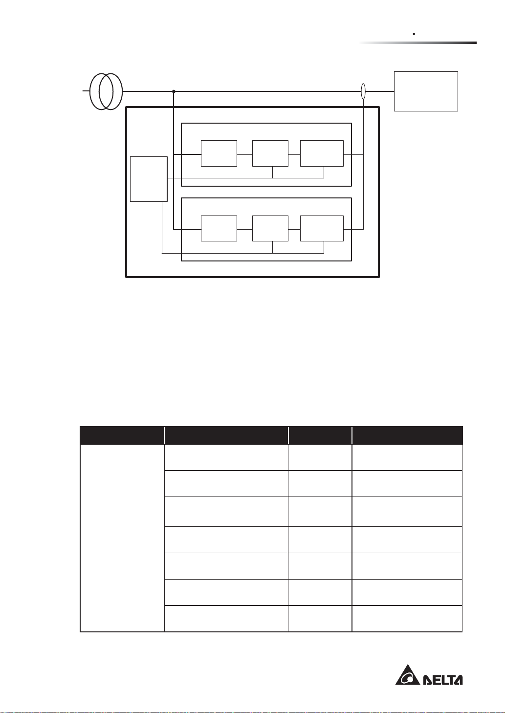
y7KHDFWLYHSRZHU¿OWHUµ$3)¶LVGHVLJQHGIRULQGXVWULDO,7DQGGDWDFHQWUHDSSOLFDWLRQVWR
control harmonics, reactive power and imbalance correction. The APF shall be connected
with a grid system and in parallel with harmonic sources (i.e. nonlinear loads).
y7KH$3)VKDOOQRWEHH[SRVHGWRUDLQRUZHWFRQGLWLRQVDQGVKDOOEHDZD\IURPDQ\ÀDP-
PDEOHÀXLGJDVRUH[SORVLYHV
yAdequate space shall be left in both front and rear of the APF for well ventilation and con-
venient maintenance.
y7RPLQLPL]H¿UHDQGHOHFWULFVKRFNKD]DUGVLQVWDOODWLRQPXVWEHFRQGXFWHGE\WKHTXDOL-
¿HGSHUVRQQHOLQDFRQWUROODEOHZRUNLQJHQYLURQPHQW
yTo minimize electric shock hazards, all maintenance work must be carried out by the
TXDOL¿HGWHFKQLFLDQDQGEHVXUHWRFXWRIIDOOSRZHUVXSSO\EHIRUHPDLQWHQDQFH
yHigh voltage hazards! It takes over 15 minutes for the DC capacitor to discharge. Please
make sure the device has discharged completely before carrying out any operation.
yTo minimize electric shock hazards, please read this Manual carefully before switching
the power on, and keep this Manual properly for permanent reference.
yWhen the APF is used in IT applications, please install an insulation resistance detection
device so that the alarm will go off when protection earth fault is detected.
1.2. Wiring Warnings
yTo prevent a possible risk of current leakage, the APF shall be earthed properly. Please
use the suggested diameter of PE wire mentioned in Table 3-1 or use equivalent cross-
section area of cooper bar to perform earthing.
yWith regard to wiring, the compensation capacity and the current-carrying capacities of
cables shall be taken into account.
yThe incoming lines of the APF shall be connected with appropriate protective devices. It is
recommended to provide every module with an over-current protective device with a third-
SDUW\FHUWL¿FDWLRQUDWHGYROWDJH9DQGUDWHGFXUUHQW$%HVLGHVWDNHWKHLQVWDOOD-
tion positions of auxiliary equipment into consideration and choose the protective device
with adequate breaking capacity.
y7KHFDSDFLW\RIWKHSURWHFWLYHGHYLFHVKDOO¿WWKDWRIWKH$3)

2
PQC Series Active Power Filter
yTo prevent scaling caused by high temperature, after the power is cut off, the operating
switch shall be allowed to cool down before being operated again.
yThe three-phase, four-wire APF is applicable to the power grid system with neutral
grounding.
1.3. Usage Warnings
ySince the APF is used for harmonic compensation of the power grid, the capacity selec-
tion of the APF shall be subject to the harmonic content to avoid poor compensation due
WRLQVXI¿FLHQWFDSDFLW\
ySince the APF is used for harmonic control, it shall be connected to harmonic current from
DQH[WHUQDOVRXUFHIRU&7WHVWLQJ&7&XUUHQWWUDQVIRUPHU
yTo guarantee sound reliability and avoid overheating, do not block or cover the air inlet
and outlet.
yThe working temperature range of the APF is -10°C - 50°C, beyond which the APF will not
work.
1.4. Storage Precautions
yPlease use the original packing material to protect the APF in order to avoid damage by
rats.
yIf the customer will not install the APF immediately after receiving the equipment, please
be sure to store the APF in a dry and ventilated indoor place, which shall be maintained
between -40°C and 70°C with relative humidity no higher than 95%.

3
Chapter 2 Introduction
1.5. Symbols
Item Symbol Meaning
1RPhase R of three-phase power supply
2SPhase S of three-phase power supply
3TPhase T of three-phase power supply
4NNeutral line
5Main grounding terminal
6EPO key
7XT Terminal board
8QF Circuit breaker
9XK Auxiliary switch

4
PQC Series Active Power Filter
Chapter 2 : Introduction
2.1 Product Introduction
The Delta active power filter series ('APF'), a harmonic compensator for the three-phase
power grid, is applied to the harmonic control of the power grid. Features of the device are
VKRZQDVEHORZ
y&RPSHQVDWHVDZLGHUDQJHRIKDUPRQLFIUHTXHQF\DQGDQ\UDQGRPO\VSHFL¿HGKDUPRQLF
yRapid dynamic responses, stable parameters and good harmonic compensation results.
y+LJKHI¿FLHQF\DQGORZORVV
yModular design offers a variety of coordination with various compensation capacities.
yThe module is hot-swappable, which is convenient for replacement and installation.
yThe system adopts an advanced 3-level structure and consists of digital signal proces-
sors (DSP), large programmable controllers and high power electronic devices, which has
excellent performance and superior reliability.
yProvides perfect system protection functions.
ySupports remote power on/ off functions via computer monitoring.
Please see the system block diagram in Fig. 2-1
.
The system is composed of modules and
a Cabinet System.The external CT is used for the detection of load current in the modules
and extraction of harmonic components, based on which, the main power controller controls
the main power circuit to generate reverse harmonic current; in this way, the load-carrying
harmonic components are counteracted. Each Cabinet System can be connected to up to 7
modules in parallel. The Cabinet System is equipped with a man-machine interface to display
the message of every module and manage the operation of every module.

5
Chapter 2 Introduction
(Fig. 2-1: System Block Diagram)
1RQOLQHDUORDG
6LQJOHSKDVHORDG
7KUHHSKDVHORDG
CT
+DUPRQLF
GHWHFWLRQRI
ORDGFXUUHQW
0DLQ
SRZHU
FLUFXLW
0DQ
PDFKLQH
LQWHUIDFH
0RGXOH
6\VWHP
3RZHUJULG
0DLQ
SRZHU
FRQWURO
0RGXOH
0DLQ
SRZHU
FLUFXLW
0DLQ
SRZHU
FRQWURO
+DUPRQLF
GHWHFWLRQRI
ORDGFXUUHQW
2.2 APF Series Product Category
The Delta APF series products can be classified as cabinet systems, embedded systems
(containing embedded frames and power modules) and power modules. Optional accessories
include embedded frames and LCD modules. Table 2-1 lists the detailed products' series,
models, capacities and wiring modes.
Table 2-1 $3)3URGXFW6HULHV6SHFL¿FDWLRQV
Series Model Capacity System
Cabinet
system
PQCA-400-50-50DC3 (4) 50A Three-phase three-wire
/ four-wire
PQCA-400-75-75DC3 (4) 75A Three-phase three-wire
/ four-wire
PQCA-400-75-150DC3 (4) 150A Three-phase three-wire
/ four-wire
PQCA-400-75-225DC3 (4) 225A Three-phase three-wire
/ four-wire
PQCA-400-75-300DC3 (4) 300A Three-phase three-wire
/ four-wire
PQCA-400-75-375DC3 (4) 375A Three-phase three-wire
/ four-wire
PQCA-400-75-450DC3 (4) 450A Three-phase three-wire
/ four-wire

6
PQC Series Active Power Filter
Series Model Capacity System
Cabinet
system PQCA-400-75-525DC3 (4) 525A Three-phase three-wire
/ four-wire
Embedded frame PQC-Frame N/A N/A
Power module PQCA-400-50-50DM3(4) 50A Three-phase three-wire
/ four-wire
PQCA-400-75-75DM3(4) 75A Three-phase three-wire
/ four-wire
LCD module PQC-LCM-D N/A N/A
yDelta APF power module
The Delta APF power module is provided with plug-in design and can be simply plugged
into the standard cabinet system, embedded system and customized cabinet to form
a front-operated, pluggable module system. Subject to the customer's requirement of
equipment capacity, the APF power modules can be easily connected in parallel for
capacity expansion.
The Delta APF power module is available in two wiring modes, i.e. 3P3W and 3P4W,
and is available in two specifications in terms of the output current, i.e. 50A and 75A.
The 3P4W module shall be connected to the neutral line, and it is able to compensate
the current of neutral line, including zero sequence fundamental current and tertiary
current; however, for the 3P3W module, it is unnecessary to connect the neutral line, and
the module is unable to compensate the current of neutral line, such as zero sequence
fundamental current and tertiary current. Fig. 2-2 shows the Delta APF power module.

7
Chapter 2 Introduction
(Fig. 2-2: External View of 75A APF Power Module)
yDelta APF Cabinet System
The APF Cabinet Systems 3P4W and 3P3W power
(Fig. 2-3: External View of the
APF Cabinet System)
modules are sharing the samecabinet. In the
applications of 3P4W, the cabinet must be connected to
the neutral line and equipped with 3P4W power
modules; in the applications of 3P3W, the cabinet is
unnecessary to be connected to the neutral line and
must be equipped with 3P3W power modules. Fig. 2-3
shows the APF cabinet system.
The system capacity depends on the specifications
& quantity of the power modules in the system. The
customers can determine the required quantities of the
power modules and the required cabinet system based
on their capacity requirements, or consult the local
distributors about the required capacity.
yDelta APF embedded system
The APF embedded system, dedicated for the customized embedded cabinets, can be
mounted in a PDU cabinet to form a slideway for the APF module and provide a socket for
plug-in connectors, of which, the APF module can be plugged in and out on the socket,
to compose a fully front-operated, pluggable module system. The embedded system can
be used individually to build a stand-alone APF system by connecting the power cable as
well as secondary cable of CT. Moreover, the embedded system can be easily connected
in parallel to extend capacity, to be exact, the embedded systems can be directly stacked

8
PQC Series Active Power Filter
and the modules are connected to each other via communication lines so as to build an
APF system with higher capacity. The embedded systems can be connected in parallel in
uncapped mode, thus, the quantity of embedded systems installed in a single cabinet can
be determined according to the installation height and heat dissipation conditions inside
the PDU cabinet.
The APF embedded system can be equipped with an optional LCD module and installed
in the customized cabinet, so that the parameter settings, alarms, running status enquiry
and other functions of the whole system can be achieved.
The 3P4W and 3P3W power modules are sharing the same socket of embedded system.
In the applications of 3P4W, the embedded system must be connected to the neutral line
and equipped with the 3P4W power modules; in the applications of 3P3W, the system is
unnecessary to be connected to the neutral line and must be equipped with the 3P3W
power modules.
Fig. 2-4
shows the APF embedded system.
7KHV\VWHPFDSDFLW\GHSHQGVRQWKHVSHFL¿FDWLRQVRIWKHSRZHUPRGXOHVLQWKHV\VWHP
7KHFXVWRPHUVFDQGHWHUPLQHWKHUHTXLUHGVSHFL¿FDWLRQVRIWKHSRZHUPRGXOHVEDVHGRQ
their capacity requirements, or consult the local distributors about the required capacity.
(Fig. 2-4: External View of the APF Embedded System)
2.3 Functions & Features
y0XOWLIXQFWLRQDVLQJOH¿OWHUFDQVLPXOWDQHRXVO\UHDOL]HWKHSXUSRVHVRIKDUPRQLFUHDFWLYH
and three-phase unbalance control.
y6XSHULRUKDUPRQLFFRQWUROHIIHFWVXSWRKDUPRQLFVRIWKHV\VWHPFDQEHHIIHFWLYHO\
¿OWHUHG
y([FHOOHQWFRPSHQVDWLRQRIUHDFWLYHSRZHUWKHGHYLFHFDQUHDOL]HUDSLGPVJUDGHUH-
sponse), precise (-0.99<PF<0.99) and bidirectional (both capacitive and inductive com-
pensations) reactive power control.
y2XWVWDQGLQJFRPSHQVDWLRQRIXQEDODQFHGWKUHHSKDVHWKHGHYLFHFDQUHDOL]HFRUUHF-
tion for either active or reactive unbalance, and can eliminate the neutral current (for the
three-phase four-wire series only).

9
Chapter 2 Introduction
yWide input voltage and frequency ranges, suitable for the applications with diesel genera-
WRUVDQGKDUVKSRZHUVXSSO\FRQGLWLRQVOLQHYROWDJH9a9
y/RZSRZHUORVVORZHUWKDQRIUDWHGGHYLFHSRZHUDQGDFWXDOHI¿FLHQF\!
y6RXQGVWDELOLW\WKHGHYLFHDFWVDVDQLQ¿QLWHLPSHGDQFHWRWKHSRZHUJULGV\VWHPDQG
has no effect on the impedance of the power grid system; it is able to produce accurate
DQGÀDZOHVVRXWSXWZDYHIRUPZKLFKKDVQRHIIHFWRQRWKHUHTXLSPHQW
y6LPSOHDQGÀH[LEOHDSSOLFDWLRQVWKDQNVWRWKHPRGXODUGHVLJQLWFDQEHHDVLO\HPEHGGHG
into other cabinets to work with PDU.
y(DV\PDLQWHQDQFHDQGFDSDFLW\H[SDQVLRQWKHPRGXODUVWUXFWXUHVXSSRUWVVLPSOHSOXJ
in replacement and capacity expansion, and the Poka-Yoke design requires no on-site
maintenance.
y:LGHFDSDFLW\FRYHUDJH$a$RIDVLQJOHFDELQHWXQOLPLWHGFRQQHFWLRQLQSDUDOOHO
of Cabinet Systems.
y$SSOLFDEOHWRDOOZRUNFRQGLWLRQVWKHGHYLFHLVDEOHWRRSHUDWHXQGHUKLJKWHPSHUDWXUHXS
to 50°C and salt spray corrosive conditions, can withstand grade-9 seismic intensity and
is compatible with the diesel engine generating system.
y8VHUIULHQGO\LQWHUIDFHLQERWK&KLQHVHDQG(QJOLVKHYHQWORJDXWRPDWLFIDXOWDODUP
alarm history and other parameter setting functions.
y&RPSOHWHIXQFWLRQVDXWRPDWLFVHOIFKHFNLQJVWDUWVHWWDEOHVRIWVWDUWWLPHHPHUJHQF\
stop (EPO), etc.

10
PQC Series Active Power Filter
2.4 Mechanism & Appearance
2.4.1 Appearance & Dimensions of the Cabinet System
(Fig. 2-5: Cabinet System Diagram - door open & door closed)
n
Control
Panel
q
Module
o
EPO
p
Breaker
r
Breaker 2
s
SPD
Item Name Description
1Control panel Displays and manages the APF parameters and status.
2EPO Emergency stop button.
3Breaker Controls the power-on and power-off of various modules
respectively.
4Module Refers to the power module of the plug-in system.
5Breaker 2 Switches on or off the SPD
6SPD Surge protection device.

11
Chapter 2 Introduction
Table 2-2 System Dimensions & Weight
Model Dimensions (W×D×H) Weight (Kg)
PQCA-400-50-50DC3 (4) 608 × 800 × 2028 mm 246Kg
PQCA-400-75-75DC3 (4) 608 × 800 × 2028 mm 246Kg
PQCA-400-75-150DC3 (4) 608 × 800 × 2028 mm 287Kg
PQCA-400-75-225DC3 (4) 608 × 800 × 2028 mm 328Kg
PQCA-400-75-300DC3 (4) 608 × 800 × 2028 mm 369Kg
PQCA-400-75-375DC3 (4) 608 × 800 × 2028 mm 410Kg
PQCA-400-75-450DC3 (4) 608 × 800 × 2028 mm 451Kg
PQCA-400-75-525DC3 (4) 608 × 800 × 2028 mm 492Kg
NOTE: The depth is 825mm when the upper handle is provided on the cabinet
door; the height is 2065mm when the hoisting ring is provided.
2.4.2 Appearance & Dimensions of the Embedded System
(Fig. 2-6: Embedded System Diagram - Overall View & Exploded View)
oFrame rConnector board
nAPF Power Module nAPF Power
Module qRight mounting rail
pLeft
mounting rail
˙

12
PQC Series Active Power Filter
Item Name Description
1APF power module APF 75A or 50A power module.
2Frame Accomodates the APF power module.
3Left mounting rail Refers to the left mounting rail of the embedded system.
4Right mounting rail Refers to the right mounting rail of the embedded system.
5Connector board Connects the APF power module and the embedded
system.
(Fig. 2-7: Back View of the Embedded System)
nCT inlet & outlet terminals
(Input at the top, output at the bottom)
pPower terminals
oCommunication
terminal block
Item Name Description
1CT inlet & outlet terminals &RQQHWWKHH[WHUQDO&7¶VLQOHWDQGRXWOHW
2Communication terminal
block
Refers to the Communication terminal block for
connection between modules and between modules
and LCD.
3Power terminals Refer to the terminals connecting to the R/S/T/N/PE
lines of the main power.
Table 2-3 Embedded System Dimensions & Weight
Model Dimensions (W×D×H) Weight (Kg)
PQCA-400-50-50DM3 440 × 522 × 174 mm 40Kg
PQCA-400-50-50DM4 440 × 522 × 174 mm 40Kg
PQCA-400-75-75DM3 440 × 522 × 174 mm 41Kg
PQCA-400-75-75DM4 440 × 522 × 174 mm 41Kg
PQC-Frame 512 × 602.5 × 180.5 mm 7Kg

13
Chapter 2 Introduction
2.4.3 Control Panel
(Fig. 2-8: Front View of the Control Panel)
rON/OFF
qLCD
sUP
tESC
uENTER
vDOWN
nNORMAL
oSTANDBY
pFAULT
Item Name Description
1NORMAL (green) When the lamp is lit, it indicates the APF system is
functioning properly.
2STANDBY (yellow) When the lamp is lit, it indicates the APF system is on
standby.
3FAULT (red) When the lamp is lit, it indicates there is a fault in the APF
system.
4LCD display The LCD can display both Chinese and English fonts.
5ON / OFF key Press and hold the key for 3 sec to switch on / off theAPF
system.
6UP key Press the key to move the menu items upward or to
increase the parameter setting value.
7ESC key Press the key to return to the previous menu or to save the
parameter setting when exit.
8ENTER key 3UHVVWKHNH\WRJRWRWKHQH[WSDJHRUWRFRQ¿UPWKH
parameter setting.
9DOWN key Press the key to move the menu items downward or to
reduce the parameter setting value.

14
PQC Series Active Power Filter
(Fig. 2-9: Back View of the Control Panel)
nDATABUS
oRS232
Item Name Description
1DATABUS Refers to the communication interface between
the control panel and modules.
2RS232 Refers to the standard 232 interface.
2.4.4 Appearance & Dimensions of the Power Module
(Fig. 2-10: External View of the Power Module)
o
nn
r
s
t
pq

15
Chapter 2 Introduction
(Fig. 2-11: Back View of the Power Module)
uv
Item Name Description
1DC fan Refers to the DC cooling fan.
2E.P.O button Refers to the Emergency stop button, which is pressed down
to shut down the device and is released to switch it on.
3LED indicators
Refer to the LED indicators of the module.
• *UHHQ1RUPDOLQGLFDWHVWKDWWKHPRGXOHLVIXQFWLRQLQJ
properly.
• <HOORZ6WDQGE\LQGLFDWHVWKDWWKHPRGXOHLVRQVWDQGE\
• 5HG)DXOWLQGLFDWHVWKDWWKHUHLVDIDXOWRQWKHPRGXOH
4DIP switches Set the module ID and terminal resistance.
5Databus
communication
ports
Refer to the ports reserved for module settings, program
update, etc.
6Mechanical lock The module shall be plugged into the cabinet system
accurately and then pushed rightward to lock, otherwise, the
fault alarm will not work properly.
7DC fans Refers to the DC cooling fans.
8Signal transfer
terminals Refer to the connecting terminals for communication signals
and CT signals.
9Inlet terminals of
the main power Refer to the connecting terminals of R/S/T/N/PE lines of the
main power.
NOTE: Since the Datasheet communication port is provided with insulation
isolation, it is safe to touch it.

16
PQC Series Active Power Filter
Table 2-4 APF Power Module Dimensions & Weight
Model Dimensions (W×D×H) Weight (Kg)
PQCA-400-50-50DM3 440 x 522 x 174mm 40Kg
PQCA-400-50-50DM4 440 x 522 x 174mm 40Kg
PQCA-400-75-75DM3 440 x 522 x 174mm 41Kg
PQCA-400-75-75DM4 440 x 522 x 174mm 41Kg
2.5 Package Inspection
yExterior
1. It is recommended to check for any damage of the outer packaging after receiving
the APF device since it may encounter some unpredictable conditions during
transportation. If any, please contact your supplier.
2. The APF cabinet and power modules are packed separately.
yInterior
1. Please check the rating label of the APF to see if the product conforms to your order.
2. Please check if any parts are damaged or loose.
3. Please check if the accessories are complete.
4. Please see the table below for the standard accessories of the APF on delivery.
Table 2-5 Standard Accessories of the APF Cabinet System
Name Quantity
Lintel Upon customer request
Baffle of module Upon customer request
User Manual 1
Other manuals for PQC Series
3
This manual suits for next models
8
Table of contents
Other Delta Water Filtration System manuals
Popular Water Filtration System manuals by other brands

GE
GE PXRQ15F Owner's manual and installation

Watts
Watts Hydro-Safe QTESPMAX-2S-10M Installation, operation and maintenance manual

Craft Brew Water
Craft Brew Water 500 user manual

LG
LG WQD74RJ5P Owners manual and operation guide

Clear2O
Clear2O GRAVITY GRP200 use and care manual

HST
HST WFS - 101545 Original instructions