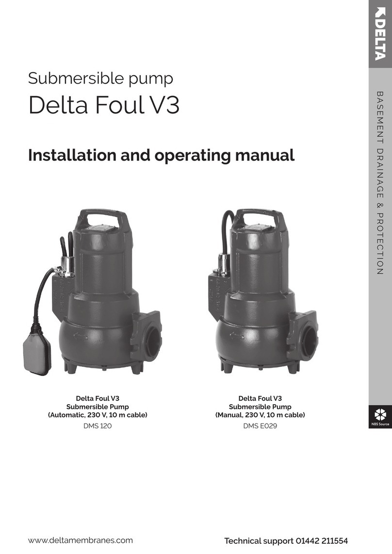
Delta FOUL V3 User manual

INNOVATION | MANUFACTURER | DESIGN | SOLUTION
WWW.DELTAMEMBRANES.COMWWW.DELTAMEMBRANES.COMWWW.DELTAMEMBRANES.COMWWW.DELTAMEMBRANES.COM
JULY 2022
DELTA
FOUL V3
INSTALLATION
GUIDE
JULY 2022JULY 2022

Commissioning Details
Property Address
Contact name
Equipment Installed
Approved Installer
Date of commissioning
Commissioning engineer
Status
Warranty period
Signature of engineer
Conditions
Fully commissioned in accordance with the manufacturers instructions
12 months from commissioning
Equipment must be on a current service agreement with approved
service organisation
Contact Tel. No.
Customer contact details
Commissioning Engineers
SERVICING PLANS
ines
and services equipment every year. Pumps running frequently due to higher water
we recommend every 6 months. Sump pumps, being mechanical devices, may
pump. All Delta Membrane pump systems can be maintained and serviced by our
recommended service companies or installing contractor.
COMMISSIONING
All sump pumps require commissioning. Commissioning provides peace of mind,
knowing that the system is installed correctly and in compliance with warranty
conditions. All Delta Membrane pump systems can be commissioned by our
recommended service companies or installing contractor.
THIS MANUAL SHOULD
BE KEPT WITH THE
PUMP STATION OR THE
HOMEOWNER
01992 523 523 | info@deltamembranes.com | www.deltamembranes.com
FOUL V3 INSTALLATION GUIDE

1
2
3
5
6
7
8
9
4
Foul V3 Overview
1.0 OVERVIEW
1.1 TECHNICAL INFORMATION
1.2 CHAMBER OVERVIEW
1.3 PARTS INCLUDED
1.4 OPTIONAL EXTRAS
Discharge Pipework & Fittings
2.0 DISCHARGE PIPEWORK & FITTINGS
2.1 SPARE PARTS
Pump Chamber Depth Limits
3.0 PUMP CHAMBER DEPTH LIMITS
Installation Guidelines
4.0 INSTALLATION GUIDELINES
4.1 PUMP STATION LOCATIONS
4.2 RC BOX DIMENSIONS
Installation Of Chamber
5.0 INSTALLATION OF CHAMBER - SECTION A
5.1 INSTALLATION OF CHAMBER - SECTION B
5.2 INSTALLATION OF CHAMBER - SECTION C
5.3 INSTALLATION OF CHAMBER - SECTION D1
5.4 INSTALLATION OF CHAMBER - SECTION D2
5.5 INSTALLATION OF CHAMBER - SECTION D3
5.6 INSTALLATION OF CHAMBER - SECTION E
5.7 INSTALLATION OF CHAMBER - SECTION F
5.8 INSTALLATION OF CHAMBER - SECTION G
Wiring Diagram
6.0 WIRING DIAGRAM
Maintenance
7.0 MAINTENANCE
7.1 HEALTH & SAFETY
Guarantee
8.0 GUARANTEE
Troubleshooting
9.0 TROUBLESHOOTING
Contents
1

1. Delta Foul V3 Overview
1.0 FOUL V3 OVERVIEW
The Delta Foul V3 is a packaged pump station designed to
collect foul water. Typically, the Foul V3 would be used to
bathroom and utility room. This pump station is not designed to
collect groundwaterfrom a cavity membrane system (see Delta
Dual V3 - DMS 164). For kitchen applications we recommend
ground applications. The chamber is manufactured from
HDPE and when installed correctly, it is able to withstand
hydrostatic forces encountered in high water tables.
The pump station is delivered as a complete package
It is designed to be installed by contractors with competent
building, plumbing and electrical skills.
recommended
the water level in the chamber becomes too high. Please see
for the Foul V3 pump station.
1.1 TECHNICAL INFORMATION
Pump Specication
Pump Type D10SA
Typical Duty (I/S) Head (m)
3 8.30
4 7.50
5 6.30
6 5.00
7 3.70
8 2.30
Power P1(kW) 1.15
P2(kW) 0.75
Current (a) 5.88
Power Phase Single
Non Switched Fuse Spur Rating (a) 13
RCBO Rating (a) 16
Cable Length (m) 10
Max. Temperature (°C) 35
Weight (kg) 13
Chamber Specication
Chamber Material High Density Polyethylene - ICO1314 grade
Size (mm)
Chamber Diameter 660
Overall Diameter 902 (across spigots)
Depth 800
Volume (L)
Below Inlet 137
Total 273
Inspection Cover Not Supplied
Clear opening to chamber (mm) 310 x 310
Fixed Inlets 3 x 110 / 160mm
Cable Duct (mm) 50
Vent (mm) 50
Discharge Connection 2” / 50mm SP Male - External to chamber
Internal Pipework Manifold 2” / 50mm BSP Class E
01992 523 523 | info@deltamembranes.com | www.deltamembranes.com
FOUL V3 INSTALLATION GUIDE
2

1.2 CHAMBER OVERVIEW
Part Description
A Screed
B Insulation
C MS20
D Basement Slab
E Inlet Pipe
F Concrete Base
G Manhole Cover
HFoul V3 Chamber
I Cable Duct
J Discharge Pipe
K Distribution Board
L Non-switched Fused Spur
M Vent Pipe
N AlertMaxx2 EC
4.0 Chamber Overview
5.0 Spare Parts
Part Description Part No.
12" Male Iron (Non-pressure) DMS-335
22" Female - 2" Male
Adaptor
DMS-337
32" Non Return Valve DMS-327
4Foul V3 Discharge Bend DMS-334
5D10SA Pump DMS-120
6Discharge Arm c/w DC65
Connector
DMS-129
6
Delta Foul V3
13 21 145
6
Part Description
AScreed
BInsulation
CMS20
DBasement Slab
EInlet Pipe
FConcrete Base
GManhole Cover
HFoul V3 Chamber
ICable Duct
JDischarge Pipe
KDistribution Board
LNon-switched Fused Spur
MVent Pipe
NAlertMaxx2
A B C D E F G H I J
K L NM
Membrane sealed to
chamber with Delta
150mm corner strip
1.3 PARTS INCLUDED
1.4 OPTIONAL EXTRAS
• Chamber - 902 x 800mm deep
• 2” Internal Pipework
• D10SA Pump (DMS-120)
• 2” Vent, Cable Duct & Discharge Male Iron for temp. site installation
• AlertMaxx2 EC High Level Alarm (DMS-599)
• 2” Discharge Pipework and various ttings (see page 5)
1. Delta Foul V3 Overview
3

2. Discharge Pipework & Fittings
2.0 DISCHARGE PIPEWORK & FITTINGS
Should you require to place an order for any of these items, please complete the form below, scan and email to
Part Description Part No. Qty Req.
2” Pipe - 3m Length (Class E) DMS-0154
2” 90° Elbow - Plain/Plain DMS-0155
2” 45° Elbow - Plain/Plain DMS-0156
2” Socket - Plain/Plain DMS-0157
2” Socket - BSP Female Thread/BSP Female Thread DMS-339
2” Male Iron - Plain/BSP Male Thread DMS-0153
2” Male Iron - Plain/BSP Male Thread (Non-pressure) DMS-335
110mm to 2” Adaptor DMS-341
Saddle Clamp - 110mm to 2” (BSP Female Thread) including 2” Male Iron
including 1.25” Male Iron DMS-0151
Saddle Clamp - 160mm to 2” (BSP Female Thread) including 2” Male Iron
including 1.25” Male Iron DMS-0152
2” Pipe Clip DMS-0159
500ml PVC Solvent Cement DMS-0158
Name:
Company Name:
Delivery/Site Address:
Email:
Phone No.: Mobile No.:
Sign.: Date.:
Please scan this order form and email to pumps@deltamembranes.com
01992 523 523 | info@deltamembranes.com | www.deltamembranes.com
FOUL V3 INSTALLATION GUIDE
4

2. Discharge Pipework & Fittings
2.1 SPARE PARTS
Part Description Part No.
1 2” Male Iron (Non-pressure) DMS-335
2 2” Female - 2” Male Adaptor DMS-337
3 2” Non Return Valve DMS-327
4 Foul V3 Discharge Bend DMS-334
5 D10SA Pump DMS-120
6 Discharge Arm c/w DC65 Connector DMS-129

3. Pump Chamber Depth Limits
If the inlet does not allow the pump chamber to be within depth limits, please contact Delta
Technical on 01992 523 523 or pumps@deltamembranes.com to discuss chamber options.
< 500mm
> 500mm
The pump chamber must be installed
A pump chamber installed more than
be serviced safely in accordance with
CDM regulations.
01992 523 523 | info@deltamembranes.com | www.deltamembranes.com
FOUL V3 INSTALLATION GUIDE
X
6

4. Installation Guidelines
4.0 INSTALLATION GUIDELINES
The following instructions are for guidance only and it is the contractors responsibility to ensure
that the installation is in accordance with the prevailing ground conditions and good building
practice, to eliminate any potential damage to the pump station either during or after installation.
Please read these instructions carefully prior to installing the chamber. If there is anything that is
unclear, please contact our technical help desk on 01992 523 523
4.1 PUMP STATION LOCATION
This station requires routine maintenance, therefore it is important that careful consideration is
taken to position the chamber in a location that allows permanent access to the chamber.
4.2 RC BOX DIMENSIONS

5. Installation of Chamber
5.0 INSTALLATION OF CHAMBER - SECTION A
Construction of reinforced concrete box
Install re-bar as per structural engineer’s
drawings.
Lay inlet and discharge pipework. Allow
minimum of 100mm.
structural engineer’s drawings.
01992 523 523 | info@deltamembranes.com | www.deltamembranes.com
FOUL V3 INSTALLATION GUIDE
8
1 2
34

5. Installation of Chamber
5.1 INSTALLATION OF CHAMBER - SECTION B
Connecting 110mm inlet pipework
to be connected.
Connect inlet pipework to the required
chamber spigot.
5 6
78

5. Installation of Chamber
5.2 INSTALLATION OF CHAMBER - SECTION C CHANNEL TO CHAMBER
Connecting discharge, cable duct and vent
Wrap the thread on a high pressure male
iron with PTFE tape.
Screw the high pressure male iron into the
socket.
duct and vent pipe and internal side of their
respective male iron.
Push discharge, cable duct and vent pipe
into their respective male iron, twisting the
pipe as it is pushed into the male iron to
remove any trapped air.
01992 523 523 | info@deltamembranes.com | www.deltamembranes.com
FOUL V3 INSTALLATION GUIDE
10
9 10
11 12

5. Installation of Chamber
Connecting discharge and cable duct
Ensure a draw cord is pulled through the
cable duct as the cable duct is built.
13
11

5. Installation of Chamber
5.3 INSTALLATION OF CHAMBER - SECTION D1 CHANNEL TO CHAMBER
Backll around chamber with concrete
Check all pipes are connected to the
chamber correctly.
with concrete (min. C35 grade) or as per
engineer’s drawings.
01992 523 523 | info@deltamembranes.com | www.deltamembranes.com
FOUL V3 INSTALLATION GUIDE
12
14 15
16

5. Installation of Chamber
5.4 INSTALLATION OF CHAMBER - SECTION D2
Backll around chamber with concrete
To be followed when installing chamber in the ground.
Fill void between soil and chamber with
concrete (min. C35 grade) or as per
engineer’s drawings.
Allow concrete to cure.
17 18
19
13

5. Installation of Chamber
5.5 INSTALLATION OF CHAMBER - SECTION D3 CHANNEL TO CHAMBER
Backll around chamber with concrete
To be followed when installing chamber in the ground with a reinforced cage.
Fill void between soil and chamber with
concrete (min. C35 grade) or as per
engineer’s drawings.
Allow concrete to cure.
01992 523 523 | info@deltamembranes.com | www.deltamembranes.com
FOUL V3 INSTALLATION GUIDE
20 21
22
14

5. Installation of Chamber
5.6 INSTALLATION OF CHAMBER - SECTION E
Preparing chamber for installation of pump
Pump out water from chamber. Manually remove any debris from chamber
and residual water using a wet vacuum.
23 24
15

5. Installation of Chamber
5.7 INSTALLATION OF CHAMBER - SECTION F(REINFORCED CAGE)
Fitting discharge to pump
Wrap the thread on the nipple glued in to the
Hand tighten the discharge arm into the
pump discharge outlet.
01992 523 523 | info@deltamembranes.com | www.deltamembranes.com
FOUL V3 INSTALLATION GUIDE
25 26
16

5. Installation of Chamber
5.8 INSTALLATION OF CHAMBER - SECTION G
Installing pump in chamber and AlertMaxx2 EC or Delta HLA
Fill chamber half full with water. Slide the DC65 over the discharge arm and
lower the pump in to chamber to release
any trapped air. Slide the DC65 up to join the
manifold to the discharge arm.
Tighten the two screws on the DC65 to seal
the pipework.
When installing a high level alarm, refer to
27 28
29 30
17

5. Installation of Chamber
through the cable duct. Coil 1m of pump and
alarm cable inside the chamber to allow for
maintenance.
Isolate mains supply and connect the pump
diagram on page 19
to test the water is discharging correctly.
EC installation instructions.
01992 523 523 | info@deltamembranes.com | www.deltamembranes.com
FOUL V3 INSTALLATION GUIDE
31 32
33 34
18
5.8 INSTALLATION OF CHAMBER - SECTION G
Installing pump in chamber and AlertMaxx2 EC
Other manuals for FOUL V3
2
Table of contents
Other Delta Water Pump manuals
Popular Water Pump manuals by other brands

Pentair Hydromatic
Pentair Hydromatic FG-3100RF Installation and operation manual

PISCO
PISCO RPV06 Series manual

Grundfos
Grundfos GT-C Installation and operating instructions

Xylem
Xylem Lowara e-MPV Installation, operation and maintenance manual

CET
CET PFP-18HPVGD-1D Instruction handbook

Pfeiffer Vacuum
Pfeiffer Vacuum Hena 26 operating instructions

Samoa
Samoa 108000 Parts and technical service guide

moyno
moyno 20352 Service manual

ASURITY
ASURITY QUIETMINI-M installation instructions

Leroy-Somer
Leroy-Somer PV4 Installation and maintenance manual

Sunlight Supply
Sunlight Supply EcoPlus Pro Series instruction manual

Oase
Oase Aquarius Universal Classic 440 operating instructions