DeLuxe Stitcher G8 User manual

Before using this Stitcher Head, all operators must study this manual and follow the
safety warnings and instructions. Keep these instructions with the G8 Stitcher Head
for future reference. If you have any questions, contact your local DeLuxe Stitcher
Company Graphic Arts Representative or Distributor.
G8 Stitcher Head
OPERATION AND MAINTENANCE MANUAL
Wire Sizes: 23-28 Ga. Round, 20x24 and 21x25 Flat
Crown Size: 1/2” (13.5 mm)
Capacity: 2 sheets to 5/16” (8 mm) Standard
2 sheets to 5/32” (4 mm) Loop
Head Serial Number :
Date Purchased :
Where Installed:
(make/model of machine)
solving your wire stitching needs for 125 years...
DELUXE
STITCHER
COMPANY INC.
®

2

3

WARNING!
G8 Stitcher Head
Machine operators and others in the work area should always wear
safety glasses to prevent serious eye injury from
fasteners and flying debris when loading, operating,
or unloading this machine.
Do not operate this stitcher head without all stitcher machine
guards in place. Do not modify the guards in any way.
Always disconnect the power supply before removing
any guards for servicing.
Never operate the machine with wire feeding through
the head unless there is stock above the clinchers,
otherwise serious damage may result.
Always turn power off when making adjustments. Always
disconnect the power cord before any disassembly work.
4
EYEWEAR
REQUIRED

6
Safety Warning .................................................................................5
Introduction ........................................................................................................7
Part Number Definition....................................................................................7
Specifications.....................................................................................................9
Installation ......................................................................................................11
Pre-Inspection................................................................................11
Inspection ......................................................................................11
Assembly Parts .............................................................................12
Mounting .................................................................................... 13-14
Operation .......................................................................................................15
Wire Threading .......................................................................... 15-16
Wire Straightening ..................................................................... 17-18
Adjustments and Settings .......................................................... 19-24
Maintenance......................................................................................................25
Lubrication ................................................................................. 25-26
Cleaning ........................................................................................27
How to Order Spare Parts .............................................................28
Troubleshooting................................................................................................29
Formed Staple Chart .................................................................. 30-31
Appendices ......................................................................................................32
Exploded Drawings with Part Number/Description/
Cross Reference/Qty. ................................................................. 32-50
Optional Equipment........................................................................51-52
Parts Index......................................................................................................53-55
Warranty........ .....................................................................................................56
Registration Card.......................................................................................... 57-58
Common Replacement Parts.......................................................................58
Table of Contents

7
The part number for each Stitcher Head can be used to define the stitcher head itself, in most
cases. The Head’s model type, mounting style, nominal wire size and crown size can all be
determined from the part number.
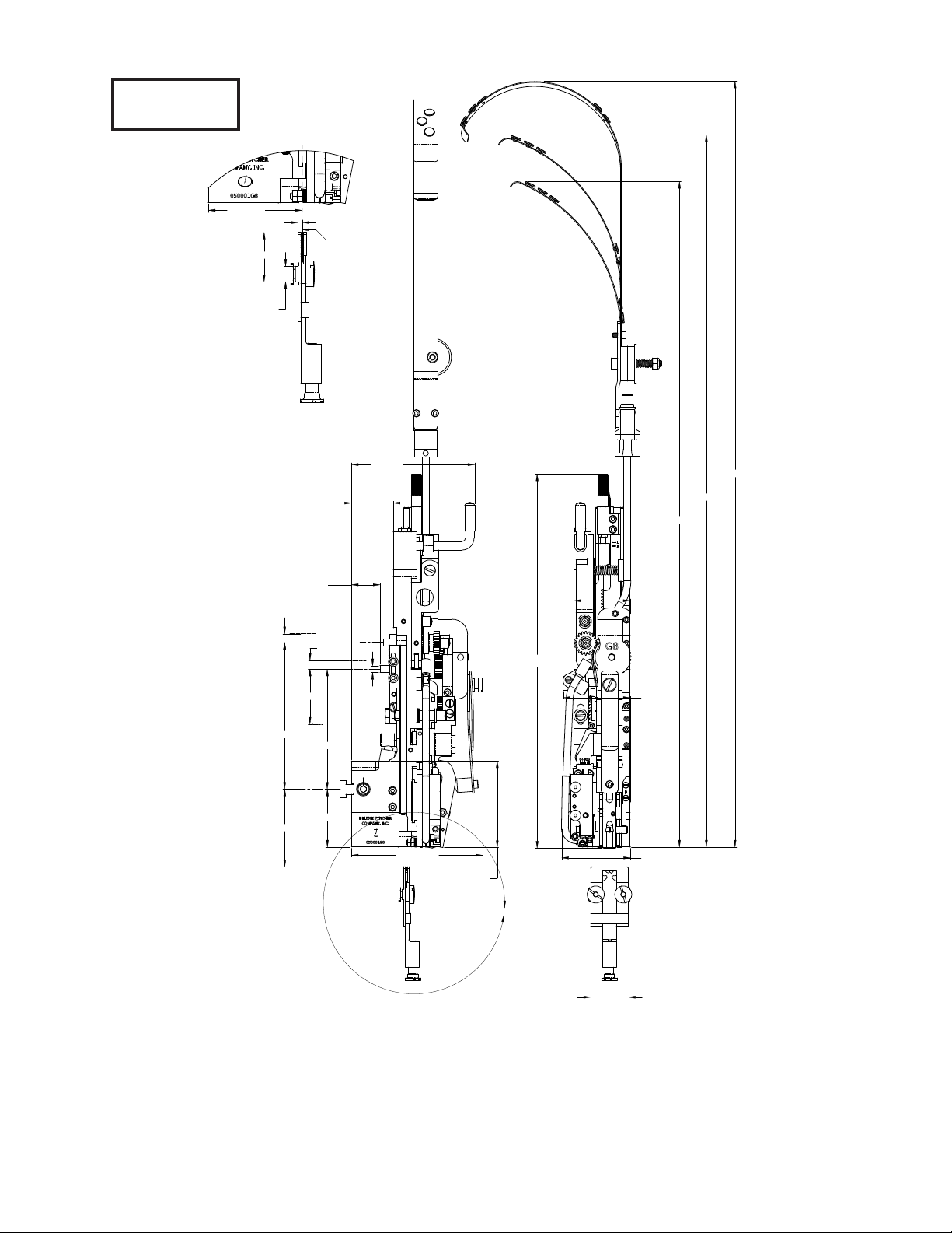
G8 P HD 24 A 1/2
1/2 = Crown size in inches
A = Mount and Wire Guide Spring Type
24 = Wire Size
HD = Head
P = Original Equipment Manufacturer
G8 = Model type
Part Number Definition
Typical Style Uses:
G8BHD ............................................................. No. 2 and M2 Wire Stitchers
G8MHD .......................................................... No. 17 and M17 Wire Stitchers
G8HD .................................................................Automatic Saddle-Stitchers,
................................................................ Gang-Stitchers, Multibinders and Others
Examples of Replacement Heads for OEM Users*:
AM Graphics / Harris / Heidelberg / Sheridan 455, 562, 690............ G8HD24A
AM Graphics / Harris / Heidelberg / Sheridan 705 ............................ G8HD24A
C.P. Bourg ............................................................................................... G8HD24D
Christensen .............................................................................................. G8HD24A
Horizon SP, SPF ...................................................................................... G8HD24D
Macey Multibinder ................................................................................ G8HD24B
McCain .................................................................................................... G8HD24A
Rosback ................................................................................................... G8HD24B
Boewe 4601 .............................................................................................. G8BOHD241/2
McCain / OmegaBinder.......................................................................... G8HD23A
Harris 855 ................................................................................................ G8HD24-HARRIS
McCain / Sheridan / Harris / Bielomatik, ECH Will \ et.al................ G8HDC24A
Heidelberg ST100, ST270, ST300, ST350............................................. G8HEHD241/2
JMZ&A (Parker) .................................................................................... G8PKHD241/2
Watkiss .................................................................................................... G8WAHD241/2
* These are just a few examples of the replacement heads available for these OEM’s.
Introduction

8
Some Head Style Examples
Figure 1 - Style Comparisons
A9086A A9086A
A9086A 9193A
9193A

9
Specifications
Weight
Shipping Weight ..............13 lbs (5.9 kg)
Box Size ...................21 x 10 x 6
Physical Dimensions
Height ...................13-9/16” (345 mm)
Width ...................2-3/4” (70 mm)
Stitching Capacity ..................Two Sheets to 5/16” (8 mm)
...................Two Sheets to 13/64” (5 mm) Loop
(Stitching capacities are highly dependent on wire and paper type, tensile strength and machine capacity.)
Wire Types ...................23 through 28 round or
...................20x24,20x25 and 21x25 flat
...................(24 gauge round standard)
...................25 gauge only for Loop
Crown Sizes ...................1/2” (13mm)
...................13/64” (5mm) Loop
Minimum Head Centers
...................2-3/64” (52mm) at two sheets to
...................1/16” (1.5mm) material thickness
...................loop = 56mm at two sheets to 2mm
Stitches Per Hour ...................20,000 or 12,000 with Loop Head
Replacement for: ...................Interlake/Acme/Champion/
...................Magnatek/M2000 heads,
...................26/26D Model Heads, or Hohner
...................52/8, 55/7, 43/6 and 48/5 Heads
...................and others
Make sure all guards are in place before
operating the stitcher head
WARNING
!

10
Dimensions
27 5/8 [702]
25 11/16 [653]
21 1/32 [611]
13 9/16 [345]
MAX.
2 3/64 [52]
2 3/4" [70]2
1/4" [57]
2 7/16 [62]
1 3/8 [34.9]
2 13/16 [71.5]
4 23/64 [110.7]
5 21/64 [135.3]
2 3/32 [53.3]
5/16 [8]
5/16 [8]
4 1/2 [114]
1 1/32 [26]
1 1/2 [38.5]
4 25/32 [121.4]
3 9/64 [80]
THICKNESS
ADJUSTMENT
THICKNESS
ADJUSTMENT
DRIVE STROKE
A
2.256 [57.30]
5/32 [3.9]
1 3/16 [30.3]
3/8 [9.5]
DETAIL A
SCALE 1.5 : 1
CENTER OF
STITCH
2 [50.8] .248 [6.3]
Figure 1

11
Installation
As you carefully unpack the head, check to make sure all components were delivered and are in
good working order. Refer to Figure 2 in this manual for reference to the following pieces:
•G8Manual
•2.0mmHexKeyWrench(G20374)
•2.5mmHexKeyWrench(G20361)
•3.0mmHexKeyWrench(G20360)
•5.0mmHexKeyWrench(G20362)
•7.0mmOpenEndWrench(G20364)
•CompleteWireGuideSpringPlateAssembly(G20278AA)
•AdjustmentKnobAssembly(G20228A)
•Short(G20279A)orLong(G20286A)WireGuideSpringAssembly
•ClincherPlateAssembly-Thick(9086A)
•Round(CA9083A)orFlat(9083C)ThickClincherPoints
•ClampBlock(9002)andClampBlockEccentric(G20124)orRearClampPin(G20366)
and Rear Mounting Bolt (G20367 or G20341)
•EitherClincherPlateBinderNut(2091),Bolt(9088)andThickClincherSlide(CA9093A)
or Clincher Plate Binder Nut (2091), Bolt (9088), Adjustable Clincher Slide (9084B),
Clincher Slide Adjusting Screw (9087) and Clincher Slide Adjusting Lock Screw
(UA4808.7).
•StitchSamples
* Note: the accessories included with the G8 will vary with the style of Head purchased
Carefully inspect the condition of the shipping container before unpacking your G8 Stitcher Head.
If the container is broken or damaged and there is evidence that the stitcher head may be damaged,
immediately notify the carrier who delivered the head and the DeLuxe Stitcher Graphic Arts
Representative from whom the G8 Stitcher Head was purchased.
Pre-Inspection
Inspection

12
Please take a few moments to fill out the registration card located on page 44 prior to beginning
installation.
Assembly Parts
Figure 2 - Assembly Parts
G20124
G20374
2mm Hex Key
G20361
2.5mm Hex Key
G20360
3mm Hex Key
G20362
5mm Hex Key
G20380
5mm T-Handle Hex Key
G20228A
G20364
7mm Wrench
CA9083A
9002
G20101
G20366
G20341
(1/2” thread)
or G20367
(8mm thread)
G20279AA
G50286SA
(Spring not shown
here, see pg. 44)
G20679A
G20181 or
G20181B
CTTT9086A
(See page 42 for
more detail on
full Clincher Plate
Assemblies.)
G20286A
9193A
HN1213
(1/2” thread)
or G20170
(8mm thread)
OPTIONAL
G20279A
G50716
OPTIONAL
OPTIONAL
OPTIONAL
OPTIONAL
G20103
OR 9083C
G20124T
OPTIONAL

13
Mounting
Figure 5 - Attaching & Removing the Clincher Plate
Figure 3 - Attaching the Wire Guide
Figure 4 - Alternate Mount Methods
Upper Cutter Block
Adjustment Bar
G20245
G20251

14
LINE UP GROOVES
Figure 5 - Attaching & removing Stitcher Heads

15
Middle Wire Tube (Figure 10). (Or with the gears engaged,
place the Adjustment Handle over the Small Gear pin and
rotate clockwise to feed the wire through. See Figure 11.)
Re-engage the gears.
4. Turn the stitcher machine on and cycle it until the wire
emerges from the Lower Wire Tube in the Cutter Block. When accomplished, proceed to wire straightening
Note: Never operate the Stitcher Head with the Wire Holder in place unless there is wire stock above
the Clincher Points.
1. Slide the Wire Holder Retaining Spring over to the side
and remove the Wire Holder (Figure 7) from the Stitcher
Head.
2. Pass the wire from the Spool over the Wire Guide Spring
between the Wire Guides, between the Washer and Wire
Oiler Felt and into the Anti-Backup Wire Unit (Figure 8).
3. Turn the Feed Release Handle clockwise (Figure 9)
to disengage the Feed Gears and guide the wire into the
Operation
Wire Threading (Figures 7 - 13)
Feed Release Lever
(Turn to disengage
position as shown.)
Figure 9 - Threading the Head
Figure 7 - Threading the Head
Wire Holder
Retaining
Spring
G20183
Wire Guide Spring
G20279,
G20286A or
G20679A
Anti-Backup Wire Unit
G50800CA
Wire Oil Felt
G20293
Figure 8 - Threading
the Wire Spring
Wire Holder
G20559BA
or G20301A
Feed Gears
Middel Wire Tube

16
Figure 11 - Threading the Head
Figure 13
Cut-out View of
Wire Threading
Figure 10 - Threading the Head
Small Feed Gear
G20112
Large Feed Gear
G20110A
Middle Wire Tube
G20144A
Figure 12 - Threading the Head
Lower Wire Tube
G20199A
Cutter Block
G20197A
Wire Straightener
Eccentric
G20206
Adjustment Handle
G20228A
Wire Guides
G20541
Wire
Feed Release Lever
G20119
(Turn to engage
position as shown)

17
Horizontal Adjustment (Figures 15-16)
Observe the direction the wire is moving as it emerges. Use a
slotted head screwdriver on the Wire Straightener Eccentric in the
Cutter Block to adjust the wire. If the wire is curved upwards, turn
the Wire Straightener Eccentric clockwise. If the wire is feeding
downward, turn the Eccentric counter-clockwise.
.010 [.25mm] GAP
Figure 16a - Wire Curls Up
Figure 16b - Wire Curls Down
Figure 16c - Straight Wire
Figure 14 - Adjust the Wire Feed Gap
Adjusting Wire Straightness (Fig. 14-17)
Figure 15 - Adjusting Wire Straightness
LOWER WIRE
RAISE WIRE
Note: Use a metal shim to set gap will simplify this step.
Wire
Straightener
Eccentric
G20206
Hex Nut
G20226
Set Screw
G20273
SKIP
UNLESS
WIRE TUBE
HAS BEEN
MOVED OR
SHIFTED
FROM
FACTORY
SETTINGS.

18
Front-to-Back Adjustment
If the Wire Guide Bars are not properly positioned, the wire will
rub against them as it exits the Cutter Block. Look at the G8 Head
from the side past both the Right and Left Wire Guide Bars (Figure
17). Make sure there is a clear view of the opening in the Fixed
Wire Cutter from the side of the G8 Head. If there is not, loosen
the Flat Head Machine Screws securing the Wire Guide Bars to the
Pivot Block and move them out of the path of the wire. Tighten the
Screws after making sure the Wire Guide Bars are even with each
other. Replace the Wire Holder and re-engage the Wire Holder
Retaining Spring.
NOTE: Depending on its size, adjust wire straightness every
3-10 lbs. of wire used approximately as follows:
5-10 lbs. Spool every 3 lbs.
10-25 lbs. Spool every 5 lbs.
25-70 lbs. Spool every 7 lbs.
70 lbs.+ Spool every 10 lbs.
In order to form a quality stitch, the
Wire Holder has to be in alignment
with the Bender Bar. Specifically,
the cut piece of wire held in the Wire
Holder has to line up with the grooves
in the Bender Bar. Poor adjustment
Aligning the Wire Holder (Figure 18a & b)
Figure 17 - Wire Guide Alignment
Fixed Wire
Cutter
G20200
Screw
G20215
(1 per side)
WIRE IN
WIRE
HOLDER
ALIGN TO
BENDER
BAR
GROOVE
WIRE
BETWEEN
BENDER
INSERT
GROOVES
Wire Holder
Adjustment Screw
G20665
Figure 18a - Wire Holder Alignment
Figure 18b - Wire Holder Alignment

19
may cause broken crowns or other poor stitching.
Load a piece of wire into the Wire Holder. Using a mirror, check to make sure the wire in the Wire
Holder is lined up with the grooves in the Bender Bar (Figure 18b). If it is not, loosen the Socket Head
Set Screw in the front of the Wire Holder and the Hex Nut (seen in Figure 15) securing the Wire Holder
Adjustment Screw (Figure 18a). Turn the Adjustment Screw until the wire is aligned with the grooves in
the Bender Bar. Tighten the Hex Nut and Set Screw to secure this setting.
Remove the wire in the Wire Holder and load another piece in the Stitcher Head. Verify that the setting
established is accurate by again checking the piece of wire with the mirror.
Before making any adjustments, make sure
your stitching machine compression setting
is set to the proper thickness of work. Make
a few sample stitches and look at the results.
Setting the Stitch Gap (Or Adjusting the Wire Draw)
To adjust the overall length (wire draw) of the stitch, disengage the Small Feed Gear by turning the Feed
ReleaseHandle1/4ofaturntotherightasshown.AdjusttheFeedRackAdjustmentKnobuntilthegap
betweenthestaplelegsallowsonlytheedgeofangernailtopassbetweenthem.
• Toextendthelengthofthestitchordecreasethegap,turntheFeedRackAdjustmentKnobclockwise.
(See upper view of Figure A)
• To shorten the length of the stitch or increase the gap, turn the knob counter-clockwise. (See lower view
of Figure A)
Centering the Stitch Gap (Or Setting Equal Length Legs)
The amount of wire on either side of the stitch gap should be the same. The gap position is controlled by
the position of the Cutter Block. As thicker work is stitched, the Cutter Block must be moved further from
the Wire Holder to keep the legs of the stitch even and the gap centered.
Adjusting the Stitch (Figure 19-23)
RIGHT LEG TOO SHORT
RIGHT LEG TOO LONG
Figure A
Adjust Length
Figure 19 - Adjusting the Wire Draw
MORE WIRE DRAW
LESS WIRE DRAW
Feed Rack
Adjustment Knob
G20173

20
For G8 Heads mounted to a machine
with an adjuster rail, loosen the two (2) Hex
Head Screws securing the Lower Cutter Block
Adjustment Bar and Cutter Block Adjustment
Connector to the Upper Cutter BlockAdjustment
Bar (both versions shown in Fig. 4). For all G8
style Heads, place theAdjustment Knob over
the Cutter Adjustment Stud as shown in Figure
20 and engage the teeth of the Cutter Block
Adjustment Rack and adjust as shown in the
following illustrations. Be sure to run a couple
of stitches after each adjustment.
1/16"[1.6mm]
TOO FAR LEFT OF
CENTER OF STITCH
WIRE LENGTH
1/16"[1.6mm]
TOO FAR RIGHT OF
CENTER OF STITCH
WIRE LENGTH
Gap of stitch is
1/16" off center to
the right. To correct.
turn the Adjustment
Knob clockwise. to
shift the Cutter Box
1/16" to the left.
Gap of stitch is 1/16"
off center to the left.
To correct. turn the
Adjustment Knob
counter-clockwise
to shift the Cutter
1/16" to the right.
Figure B
Adjust Left
Figure C
Adjust Right
Figure 21 - Adjusting the Stitch Figure 22 - Adjusting the Stitch
Figure 20 - Adjusting the Stitch
Hex Head
Screw
G20289
Cutter Box
G20197BAA
Lower
Cutter Block
Adjustment
Bar
G20242
Cutter Block
Adjustment
Connector
G20246
Upper Cutter Block
Adjustment Bar
G20245 or
G20251
Adjustment
Knob
G20228A
Cutter Block
Adjustment
Rack
G20143
Always disconnect the power supply
before making any adjustments or
servicing the head.
WARNING
!

21
Aligning the Clincher Plate (Figures 24-27)
In order to produce properly clinched staples, the center of the Clincher Plate (round or flat, thick or
thin) must be exactly in line with the Driver both left-to-right and front-to-back.
Front-to-Back Adjustment
Manually activate the G8 until the Stitcher Head is at the bottom of its stroke and the Driver is touch-
ing the top of the Clincher Plate. Looking from
the side of the Stitcher Head, make sure the rib
of the Driver is aligned with the center of the gap
between the front and back plates of the Clincher
Plate Assembly. All adjustments are made to the
screws in the back of the G8 while the Stitcher
Head is removed from the Stitcher Machine.
Loosen the two (2) Socket Head Set Screws in
the side of the Head. If the Driver is positioned
in front of the Clincher Plate then the upper
Adjustment Set Screw must be turned counter-
clockwise until the Screw sticks out slightly from
the back of the Head, while the lower Screw
remains under flush.
If the Driver is positioned in back of the Clincher
Plate then the lower Adjustment Set Screw must
be turned counter-clockwise until it sticks out
slightly from the back of the Head, while the
upper Screw remains under flush.
Set Screw
G20229
Set Screw
G20191
LOWER
ADJUSTMENT SET
SCREW
CORRECT SETTING.
CENTER LINE OF BOTH STITCH
& DRIVER ARE ALIGHED
The ideal stitch has the center of gap
aligned to the center of the finished stitch.
Figure D
Correct Stitch
Figure 23 - Adjusting the Stitch
UPPER
ADJUSTMENT SET
SCREW
Other manuals for G8
2
Table of contents
Popular Binding Machine manuals by other brands

Rhin-O-Tuff
Rhin-O-Tuff APES-14-77 Operator's training manual

ACCO Brands
ACCO Brands GBC G1 Operation & instruction manual

Fellowes
Fellowes Quasar+ 500 quick start guide

Q-Connect
Q-Connect STANDARD COMB BINDER 8 quick guide

GBC
GBC DocuBind P400 operating instructions

Olympia
Olympia SB 950 operating instructions