DeLuxe Stitcher 7AW User manual

Before using this Stitcher, all operators must study this manual and follow the safety
warnings and instructions. Keep these instructions with the #7/7AW Stitcher for
future reference. If you have any questions, contact your local DeLuxe Stitcher
Graphic Arts Representative or Distributor.
#7/7AW Stitchers
OPERATION AND MAINTENANCE MANUAL
7 Series Stitchers....................Electric Clutch
7AW Stitcherw/Motor.........115V and 60HZ
7BW Stitcherw/ Motor........230V and 50HZ
7CW Stitcher w/o Motor.......115V and 60HZ
7EW Stitcherw/o Motor......230V and 50HZ
Machine Serial Number :
Head Serial Number :
Date Purchased :
DELUXESTITCHER
COMPANY INC.

WARNING!
#7/7AW Stitchers
Operators and others in the work area should always wear
safety glasses to prevent serious eye injury from
fasteners and flying debris when loading, operating,
or unloading this machine.
Do not operate this stitcher without all guards in place.
The stitcher will not operate without the front guard
closed properly. Do not modify the guards in any way.
Always disconnect the power supply before removing
any guards for servicing.
Never operate the machine with wire feeding through
the head unless there is stock above the clinchers,
otherwise serious damage may result.
Always turn power off when making adjustments. Always
disconnect the power supply before any disassembly work.
2

Introduction ......................................................................................................4
Operating Adjustments ..........................................................................................5
Opening and Closing the Stitcher Head Door ..............................6
Adjusting the Machine for Thickness of Work ..............................6
Recommended Wire Sizes ..........................................................7
Wire Threading ..............................................................................8
Wire Straightening ........................................................................9
Adjustments and Settings......................................................................................10
Adjusting the Left Leg ..................................................................10
Adjusting Both Legs ....................................................................11
Adjusting the Clincher Points ......................................................11
Maintenance ......................................................................................................12
Lubrication and Cleaning..............................................................13
Ordering and Replacing Spare Parts ..........................................15
Clutch-Brake Maintenance ..................................................................................18
Troubleshooting ....................................................................................................23
Assembly Drawings ..............................................................................................25
Part Number / Description Cross-Reference ........................................................28
Registration Card ..................................................................................................32
Wear/Replacement Parts ....................................................................................33
Warranty ......................................................................................................34
Table of Contents
3

The Model Number 7 Book Stitcher is a combination light and heavy duty stitcher
designed to staple both flat and saddle work ranging in thickness from a few sheets to
7/8" (22.2mm).
The recommended wire sizes to be used on the Number 7 Stitcher are as follows:
round wire - 28 to 24 and flat wire - 20 x 24, 20 x 25, and 21 x 25. The above wire
sizes can be used without changing parts. However, for heavy flat work it is
recommended that the special flat work Driver be substituted for the standard Driver.
The Number 7 is easily adjustable for changing from saddle work to flat work by
means of the tilting work table. Figure 1 shows the stitcher set for flat work operation.
An adjustable work guide and adjustable work stops are easily attached to the work
table and provide for accurate registering of flat work for uniform spacing of staples.
When the work guide is not being used it can be attached to the right side of the
stitcher's frame, where screw holes are provided for attaching the guide (using the
same screws which attach it to the work table), thereby providing a convenient storing
place for the guide. In addition, work table extensions, both front and back, are
provided to accommodate the larger sizes of work to be stitched.
The Model Number 7 is foot-switch operated and is belt driven by a 1/3, HP motor,
making possible operating speeds up to 125 stitches per minute. The motor is
mounted on an adjustable bracket which can be raised or lowered for adjusting the
tension of the driving belt. The machine driving mechanism is thoroughly shielded
thus preventing the possibility of personal injury.
Introduction
4

5
Operating Adjustments
The quality and quantity of work that can be stitched on the Number 7 machine is dependent upon
the operator making the various operating adjustments as accurately as possible. The following
illustrated instructions and information are provided so that the operator will clearly understand how
to make the required operating adjustments.
Figure 1 - the Number 7 Stitcher
WIRE STRAIGHTENERS
NUMBER 7 HEAD
WORK GUIDE
WORK TABLE
(FLAT WORK POSITION)
WORK STOPS
WORK THICKNESS GAUGE
ADJUSTING HEAD WHEEL
ADJUSTABLE MOTOR BRACKET
PROTECTIVE V-BELT DRIVE
WORK THICKNESS GAUGE
SWITCH AND OVERLOAD
CIRCUIT BREAKER

To open the stitcher head Door, press the Door Latch (1) to the right, thereby releasing the Latch
from the Latch Catch and permitting the Door to swing to an open position (shown by the dotted
line in Figure 2). To close the Door, first
check that the machine is at the top of its
stroke (the Supporter (2) will be at a
forward position), then depress the
Supporter back to its retracted position
with one hand and close the Door with
the other hand while compressing the
Latch (1) until it catches in the Latch
Catch.
Stitcher Head Door (Figure 2)
6
Turn the thickness adjustment handwheel (1) counter-clockwise (to the left) until the Column Gauge
(2) has raised sufficiently to allow a sample of work to be stitched to be inserted between the Gauge
and the Gauge Shelf, as shown in Fig. 3. With work held in this position, turn the handwheel (1)
clockwise (to the right) until the work is firmly clamped between the Gauge (2) and the Gauge Shelf;
Adjusting Thickness (Figure 3)
Figure 2 - Opening and Closing Door
Do not slam door shut, or attempt to force door shut while
cycling machine or with machine positioned at bottom of stroke.
Failure to comply with this may result in damage to the stitcher head.
rCAUTION
!
1
2

7
Figure 4 - Recommended Wire Sizes
then turn the handwheel to the left, raising
the Gauge just far enough to permit work
to be withdrawn from between the Gauge
and the Gauge shelf. After withdrawing
the sample work, turn the handwheel to
the right until the Gauge has returned to
the point at which it clamped the work.
Figure 3 - Work Thickness Adjustment
1
2
Wire Gauge Type of Work 20# Stock
Install 7089E Driver / 7257B Clincher Points for:
28 Round . . . . . . . . . . . . . . Light Flat or Saddle . . . . . . . . . . . . . . 2-10 Sheets
27 Round . . . . . . . . . . . . . . Light Flat or Saddle . . . . . . . . . . . . . . 2-10 Sheets
26 Round . . . . . . . . . . . . . . Light Flat or Saddle . . . . . . . . . . . . . . 2-10 Sheets
25 Round . . . . . . . . . . . . . Medium Flat or Saddle . . . . . . . . . . . . 10-50 Sheets
24 Round . . . . . . . . . . . . . Medium Flat or Saddle . . . . . . . . . . . . 10-50 Sheets
Install 7089F Driver / 7024B Clincher Points for:
20 x 25 Flat . . . . . . . . . . . . . Heavy Flat Only . . . . . . . . . . . . Over 50 Sheets
21 x 25 Flat . . . . . . . . . . . . . Heavy Flat Only. . . . . . . . . . . . . Over 50 Sheets
20 x 24 Flat . . . . . . . . . . . . . Heavy Flat Only. . . . . . . . . . . . . Over 50 Sheets
* Note: 21x25 flat wire can be used for Heavy Saddle applications but it is not
recommended. If 19x21-1/2 flat wire is required, contact your Graphic Arts
Representative for the recommended parts.

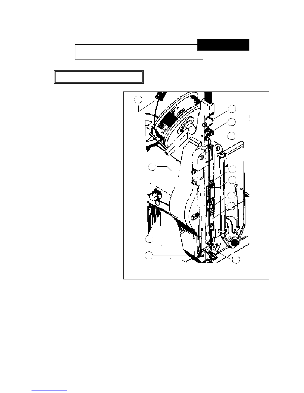
Open the Stitcher Head Door (1).
Pass the wire from the Spool over
the Wire Guide Spring (2),
threading the wire between the
Guide Studs on the Guide Spring
and through the Oiler Felt in the
Retainer (not shown). Thread the
wire between the Rolls of the two
sets of Wire Straighteners (3) and
(4). Pass the end of the wire behind
the Wire Clip (5) and then pull the
wire down until it extends to just
below the Wire Cutter Holder (6).
Push the Wire Holder Slide (7) to
the left. With the Slide held in this
position, lay the wire well back in
the slot (8) in the Wire Cutter Holder
then release the Slide (7) allowing it
to close over and retain the wire in
the slot (8). Slide the Wire Retainer
(9) up, thereby uncovering the
groove in the Wire Guide (10). Lay
the wire in the groove and then slide
the Retainer (9) down securing the
wire in the groove. Turn the
machine over manually until the
wire
automatically falls in place between
the Moveable and Fixed Grips (11) and (12).
The wire is now threaded in the Head. However, before operating the Stitcher under power, turn the
machine over manually a few revolutions and observe that the wire is feeding freely and is being
cut off by the Cutters in the Cutter Holder. Then close the stitcher head door and check that the wire
is feeding in a straight vertical line, as directed in the following paragraph.
8
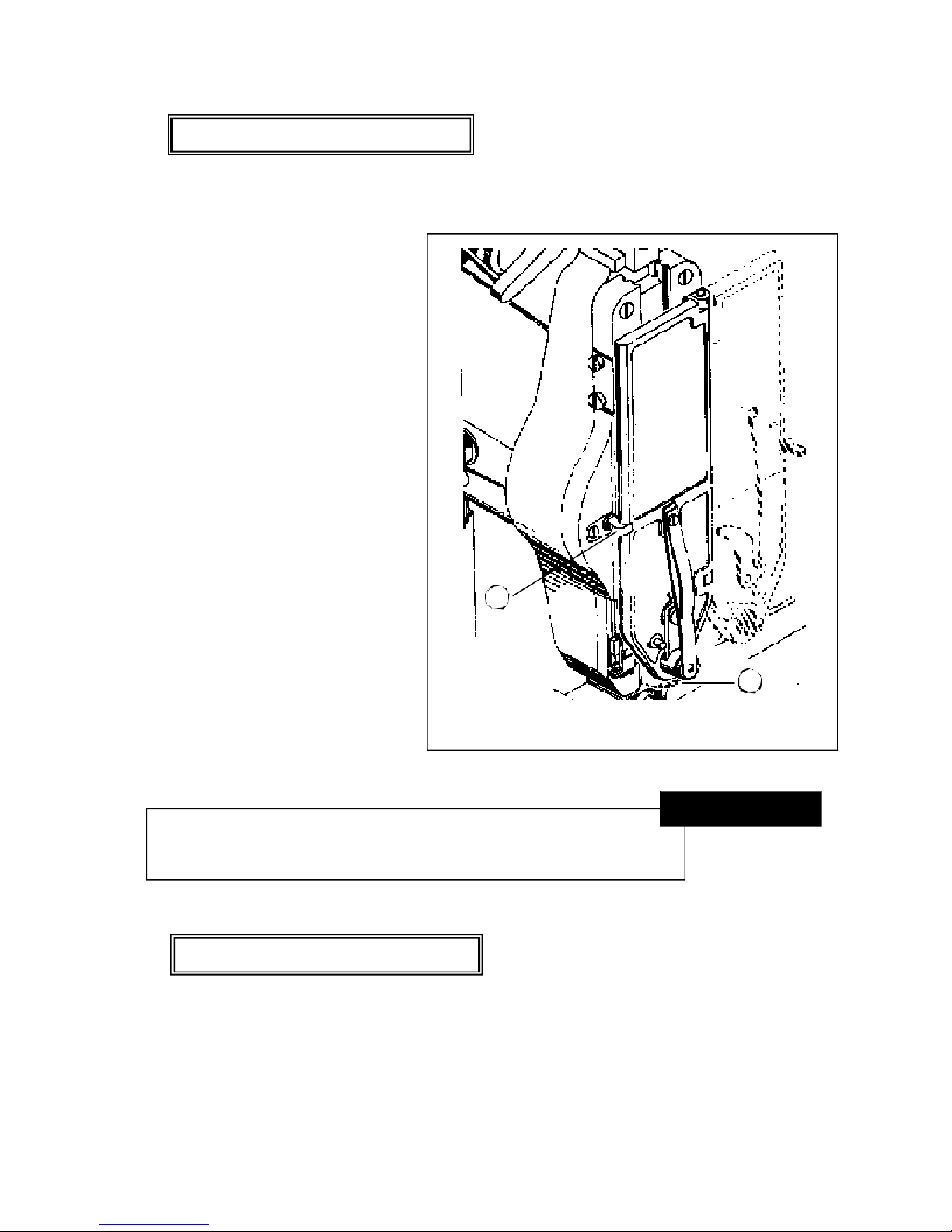
Wire Threading (Figure 5)
Always disconnect the power supply before
making any adjustments or servicing the stitcher.
rWARNING
!
Figure 5 - Wire Threading
1
4
3
2
5
11
8
76
10
9
12

9
In order to insure continuous
operation of the Stitcher, it is
important that the wire when
being fed into the Swivel,
enters in as close to a
straight-vertical line as
possible. To check this
condition and make the
necessary adjustments,
proceed as follows.
Disengage the Swivel Spring
(1) from the Swivel (2) and
withdraw the Swivel from its
Bushing (3). Turn the
machine over manually and
observe by looking directly
into the Swivel Bushing (4)
that wire is being fed in a
vertical line, as shown in
insert Figure 6. If the wire is
feeding to the left or to the
right, turn the Lower Wire
Straightener Eccentric
Handle (5) clockwise or
counter-clockwise as
required, until wire feeds in a vertical line. If wire is feeding in a straight line with respect to
the left and the right but tends to curl forward or backward, turn the Upper Wire Straightener
Eccentric Handle (6) until this condition is remedied. After the necessary adjustments have
been made, replace the Swivel in its Bushing and attach the Swivel Spring.
Wire Straightening (Figure 6)
Do not slam door shut, or attempt to force door shut while
cycling machine or with machine positioned at bottom of stroke.
Failure to comply with this may result in damage to the stitcher head.
rCAUTION
!
Always disconnect the power supply before
making any adjustments or servicing the stitcher.
rWARNING
!
Figure 6 - Wire Straightening
42
3
1
5
6

If staple is cut off center causing one leg to be longer than the other, the left leg of the staple can be
shortened or lengthened as follows. Loosen but do not remove the two Wire Feed Adjustment Rack
Screws (1) permitting the Adjustment Rack (2) to be moved up or down. If a shorter left leg is
required, move the Adjustment Rack (2) up slightly. If a longer left leg is required, move the
Adjustment Rack down slightly.
After positioning the Adjustment Rack,
tighten the Adjustment Rack Screws (1) and
turn the machine over a few revolutions to
check the stitches. If the staple is still off
center, repeat the preceding steps until a
perfect stitch is obtained. With a little
experience, the operator will soon learn how
much to raise or lower the Adjustment Rack
to obtain the correct staple leg length. After
the final adjustment has been made, securely
tighten the Adjustment Rack Screws (1).
Adjusting the Left Leg (Figure 7)
Figure 7 - Adjusting the Left Leg
If the machine is operated on work thicker
than it is set to handle, damage will result. rWARNING
!
10
2
1
Adjustments and Settings

If the staple legs are centered but are too
long or too short, adjust amount of wire feed
as follows:
Loosen the Adjustment Lever Eccentric
Bushing Screw (1) sufficiently to release the
knurled Eccentric Bushing (2). If longer
staple leg is required, turn the Eccentric
Bushing (2) clockwise (toward the front of
Stitcher); if shorter staple leg is required, turn
the Bushing counter-clockwise (toward rear
of the Stitcher).
After adjusting the Eccentric Bushing,
tighten the Bushing Screw (1) and turn the
machine over a few revolutions to check the
stitches. If the legs are still not the required
length, repeat the preceding steps until a
perfect stitch is obtained. With a little
experience the operator will soon learn how
far to turn the Eccentric Bushing to obtain the
desired staple leg length.
After final adjustment has been made,
securely tighten the Eccentric Bushing
Screw (1).
11
Adjusting Both Legs (Figure 8)
Figure 8 - Adjusting Both Legs
If the staples are being loosely clinched (see Staple N and 0 in the Trouble Shooting Chart on page
15), requiring the raising or lowering of the Clinchers, proceed as follows.
Adjusting the Clincher Points (Figure 9)
2
1

Remove the Retaining Screw (1)
securing the Clincher Slide (2) to
the Actuating Link Plunger (3).
Loosen the Plunger Set Screw (4)
and then turn the Plunger (3) to the
left or to the right as required, to
raise or lower the clincher slide.
Replace and tighten the Retaining
Screw (1) in the Plunger Screw
hole now facing the front of the
machine, and then tighten the
Plunger Set Screw (4).
12
Figure 9 - Adjusting the Clincher Points
To insure continuous operation of the Number 7 Stitcher the operator should be sure that the
machine is regularly lubricated and carefully maintained. The operator should periodically inspect
all moving parts for signs of wear and when required, replace the worn parts. Some parts such as the
Wire Cutters, the Wire Grip, and the Driver have been so designed as to provide duplicate cutting and
gripping surfaces. If after continuous usage, the original cutting or gripping surfaces show signs of
wear, their position in the head can be reversed, thereby providing a new surface and lengthening the
life of the part.
The following instructions are provided so that the operator will clearly understand how to
lubricate the machine, how to reverse or replace the parts referred to above, and how to adjust the
clutch.
Maintenance
41
23

13
Use a S.A.E. Number 10 oil for lubricating the Number 7 Stitcher. Machines that are in constant
operation should be lubricated daily. Machines that are operated periodically should be lubricated just
prior to running a job.
Usually only a drop of oil is required at each point of lubrication in the Stitcher Head. Care must
be taken that those parts of the machine that contact the work being stitched are free from oil.
Lubricate regularly instead of excessively. Excessive oiling will result in work becoming oil-spotted.
Figure 10 - Lubrication Points
Lubrication (Figure 10)
6
5
3
2
4
1
8
7

14
After lubricating the machine,
wipe off any excessive oil.
• Oil hole in the Wire Feed
Slide (1).
• Oil hole in the Wire Cutter
Holder (2).
• Oil hole in the Swivel
Operating Cam Roll Stud (3).
• Moving parts in this area
(4). It is recommended that a
toothpick tipped with oil
moistened cotton dressing be
used to lubricate these parts.
(Apply just enough oil to keep
these parts moist).
• Oil slot in the Door (5) for
the Swivel Operating Lever.
• Opening in Swivel Bushing (6).
• Oil tube in machine frame (7) for lubricating Main Shaft Connecting Link.
• Oil cup in frame (8) for lubricating main Drive Shaft.
• Oil cup in frame (9) for lubricating main Drive Shaft.
• Oil hole in Clincher Driving Bar Roll Stud (10).
Figure 10 - Lubrication Points
9
10

The Wire Cutters have four cutting
edges, each of which may be used by
reversing the ends and position of the
Cutters in the Cutter Holder. To remove
and replace the Cutters proceed as fol-
lows. Raise the Wire Cutter Retainer (1)
and slide the Upper Wire Cutter (2) out
from the Cutter Holder (3). Raise the
Lower Wire Cutter (4) to the Upper Wire
Cutter position and then slide the Cutter
from the holder.
To replace the Cutters, first insert the
Cutter that is going to be the Lower Wire
Cutter into the Cutter Holder, being sure
that the slot in the center of the Cutter is
toward the rear of the machine. Slide the
Cutter into the Holder until it drops down
to its bottom position. Slide the second
Cutter into the Holder and then lower the
Cutter Retainer (1) back into operating
position, thereby locking the Cutters in
the Holder.
Turn the machine over manually and
check that the Cutters are operating
freely.
Figure 11 - Removing the Wire Cutters
15
Removing the Wire Cutters (Figure 11)
2
1
3
4

The Fixed Wire Grip (1) has two
saw-toothed gripping surfaces
permitting the reversing of the Grip
when one side shows signs of wear. To
remove and replace the Grip, proceed as
follows. Disengage the Moveable Wire
Grip Spring (2) from the Moveable Wire
Grip (3). Remove the Wire Grip
Retaining Screw (4) permitting the
removal of the Fixed Wire Grip (1) from
the Grip Holder (5). Reverse and replace
the Grip in the Grip Holder, replace and
tighten Grip Retaining Screw, and
re-engage the Spring with the Moveable
Grip.
16
Figure 12 - Removing the Wire Grip
Removing the Wire Grip (Figure 12)
If the machine is operated on work thicker
than it is set to handle, damage will result. rWARNING
!
1
3
4
2
5

17
After installing any new part, turn the machine over
manually and check that the head operates freely.
Do not operate machine under power until
certain that head is operating freely.
rWARNING
!
The Driver is double-ended and when
one end is worn or damaged, it can be
reversed thereby providing a new
driving surface. To remove the Driver,
proceed as follows. Set the Stitcher for
maximum thickness work. (refer to the
paragraph on page 2). Turn the machine
over manually to the point where the
Driver (1) is at its highest position and
the release hole (2) in the Driver is still
accessible.
Disengage the Supporter Spring Rod
from the back of the Supporter (3) and
then move the Supporter to its retracted
position. Insert the Driver Release Pin
(4), supplied with the Stitcher, in the
release hole in the Driver, thereby
depressing the Driver Retaining Spring
At the same time, push the Driver down
until it can be withdrawn from the
bottom of the Bender Bar.
Figure 13 - Removing the Driver
Removing the Driver (Figure 13)
3
1
2
4

18
Clutch-Brake Maintenance
This stitcher is equipped with a solenoid actuated, continuous trip, wrap spring, clutch-brake unit.
It is a dependable device that seldom needs service, but should a malfunction occur, the following
information will serve as a service and trouble shooting guide for maintenance of this unit.
The actuator is a simple straight-forward mechanical linkage. When the actuator does not trip the
following checks should be made.
Always disconnect the power supply before
making any adjustments or servicing the stitcher
rWARNING
!
Actuator
Problem Cause and Remedy
No power to the Coil Check all wiring and switching in the
Clutch actuating system.
Lack of continuity in the Replace the Coil
Coil Windings
Mechanical binding of The Coil may have shifted or the Plunger end may
the Plunger have mushroomed due to striking the Backstop. In
the latter the Plunger may be filed to its true diameter.
Insufficient clearance for the Adjust the Linkage as needed
Actuator over the Stop Collar
Actuator loaded by the Braking force is exceeding the limits of the Brake
Stop Collar so hard that the or the Differential setting of the unit is too close
Actuator cannot be pulled by (see Assembly & Disassembly for instructions)
the Coil.
Figure 27 - Actuator Checklist

With the brake engaged (full limit of output), the input hub should be free to rotate by hand. With the
clutch engaged, the input and output hubs should rotate together. If the unit does not rotate in either
of these modes, the clearance between the hubs of the unit on the shaft may have been disturbed or
damaged. See Assembly/Disassembly instructions for re-adjusting.
Listed below are additional checks to be made if the clutch does not function correctly.
19
Clutch and Brake Springs
Problem Cause and Remedy
Clutch Brake does not 1. Drive Spring may be broken at the
drive but Input Motor turns crossover point from an overload caused by a jam.
Replace the Spring and check the Hubs for damage.
2. The Control Collar may not snap forward
because of foreign matter restricting movement.
Clean unit.
3. Actuator Assembly does not pull in.
Clutch Brake jams and 1. Spring tang broken off Drive Spring not allowing the
stalls Input Motor Clutch to disengage while the Brake is engaged.
Replace the Drive Spring.
2. Clutch output is bound up. Check the clearance
between the Output Hub and the Brake Hub.
3. Completely out of adjustment caused by losing an
internal Spring tang. Replace Spring.
Output does not repeat 1. Not enough inertia to actuate Brake.
stopping point 2. Tang broken off the Brake Spring.
Replace the Spring.
3. Adjustable Collar Locking Screw may be loose
allowing Adjusting Screw to rotate.
Figure 27 - Actuator Checklist

When disassembling the Clutch-Brake unit, always mark the Spring Tang locations with reference
to which slots they go in if the same Springs are to be used in re-assembly.
To disassemble the Clutch-Brake unit it will first be necessary to remove the Drive Pulley from the
stitcher by removing the V-belt and Pulley Washer (7679) and then by disconnecting the Anchor Strap
(7680) from the Clutch Plate. Disconnect the wires from the Solenoid, swing the Anchor Bracket
down out of way and carefully slide the Pulley and Clutch off as a unit. Remove the Drive Pulley
from the Input Hub. Next, release the Actuator Lever so that the Clutch is engaged and the Brake is
released. Remove the Retaining Ring and Shim Washer, if any, from the input Hub end. Remove the
Input Hub by rotating opposite to the drive direction. Remove the Retaining Ring and Shim Washer,
if any, from the Mounting Plate end. Remove the Output Shaft Springs and Control Collar assembly
by rotating the Output Shaft in the drive direction. (DO NOT DISASSEMBLE THE BRAKE HUB
FROM THE MOUNTING PLATE.) Remove the Control Collar from the Output Shaft and Spring
assembly by extracting towards the Brake Spring end.
20
Disassembly
Replace the Clutch, Brake and Anti-Back Up Springs as required. Assemble the Springs concentric
and square to the Output Shaft. Assemble the Control Collar over the Output Shaft and Spring
Assembly, by inserting from the Brake Spring end. It will be necessary to extend the Brake Spring
using long needle-nose pliers. Place the Brake Spring tang in any one of the nine (9) Control Collar
slots at random Assemble the Output Shaft, Springs and Control Collar assembly to the Mounting
Plate assembly by rotating the Output Shaft in the drive direction. Assemble the Retaining Ring to
the Output Shaft at the Mounting Plate end with the smooth surface facing the Brake Hub. Check end
play between the Hub and the Retaining Ring with a feeler gauge. There should be .004 to .010 end
play. Use shim washer to adjust if not. Rotate the Output Shaft in the drive direction, until it
reaches a full brake position. With the Clutch Spring Tang not in a slot, insert the Input Hub by rotat-
ing opposite to the drive direction. Select the one of ten (10) Control Collar slots for the Clutch Spring
Tang that will provide a .38 to .50" circumferential overtravel of the Control Collar when released.
At this point it may be necessary to reselect one (1) of the nine (9) Control Collar slots for the Brake
Spring Tang. Release the Actuator Lever, remove the Clutch Spring Tang from the slot, then move
the Control Collar axially towards the Input Hub end and rotate it opposite to the drive direction to
Assembly
This manual suits for next models
1
Table of contents
Other DeLuxe Stitcher Booklet Maker manuals