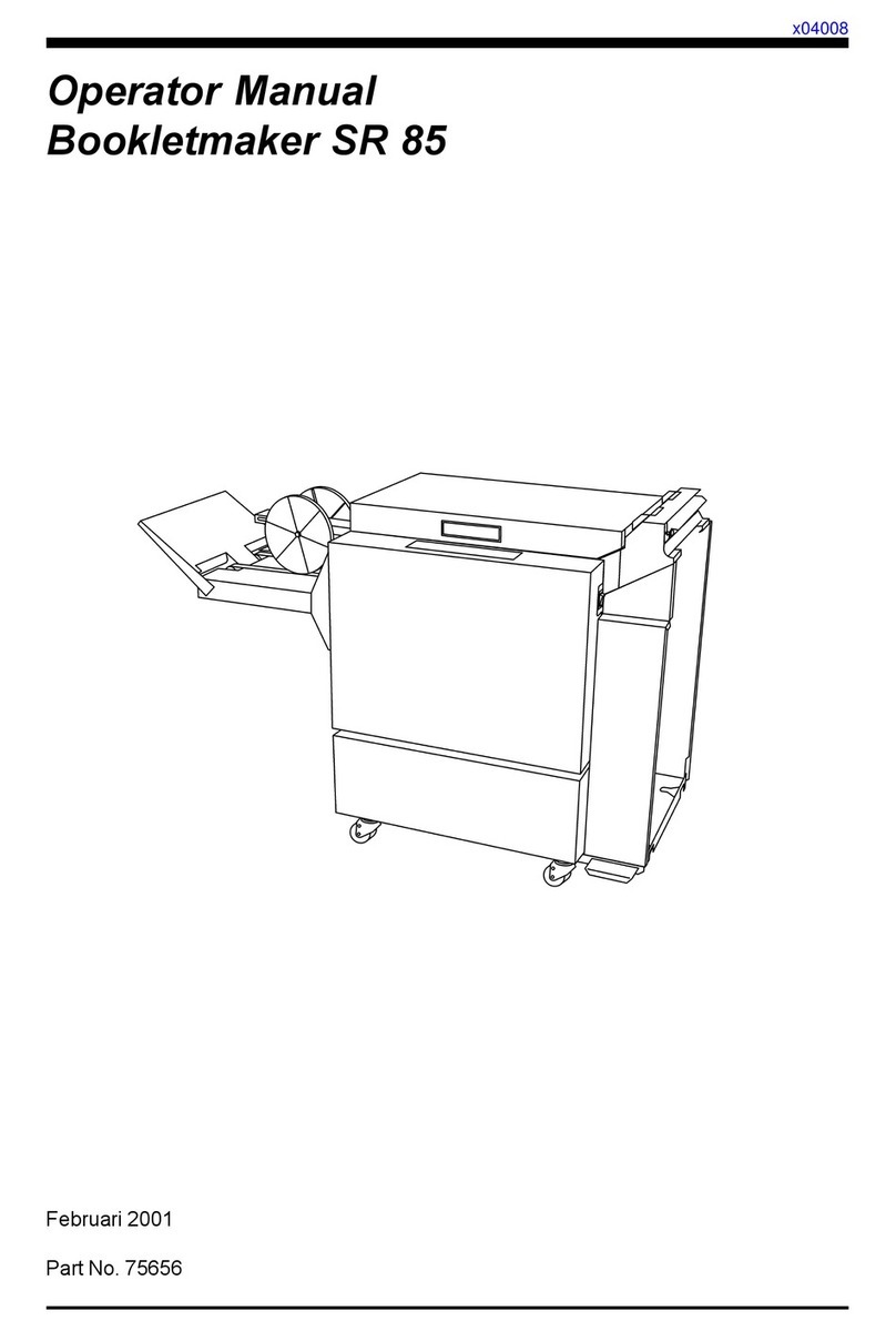
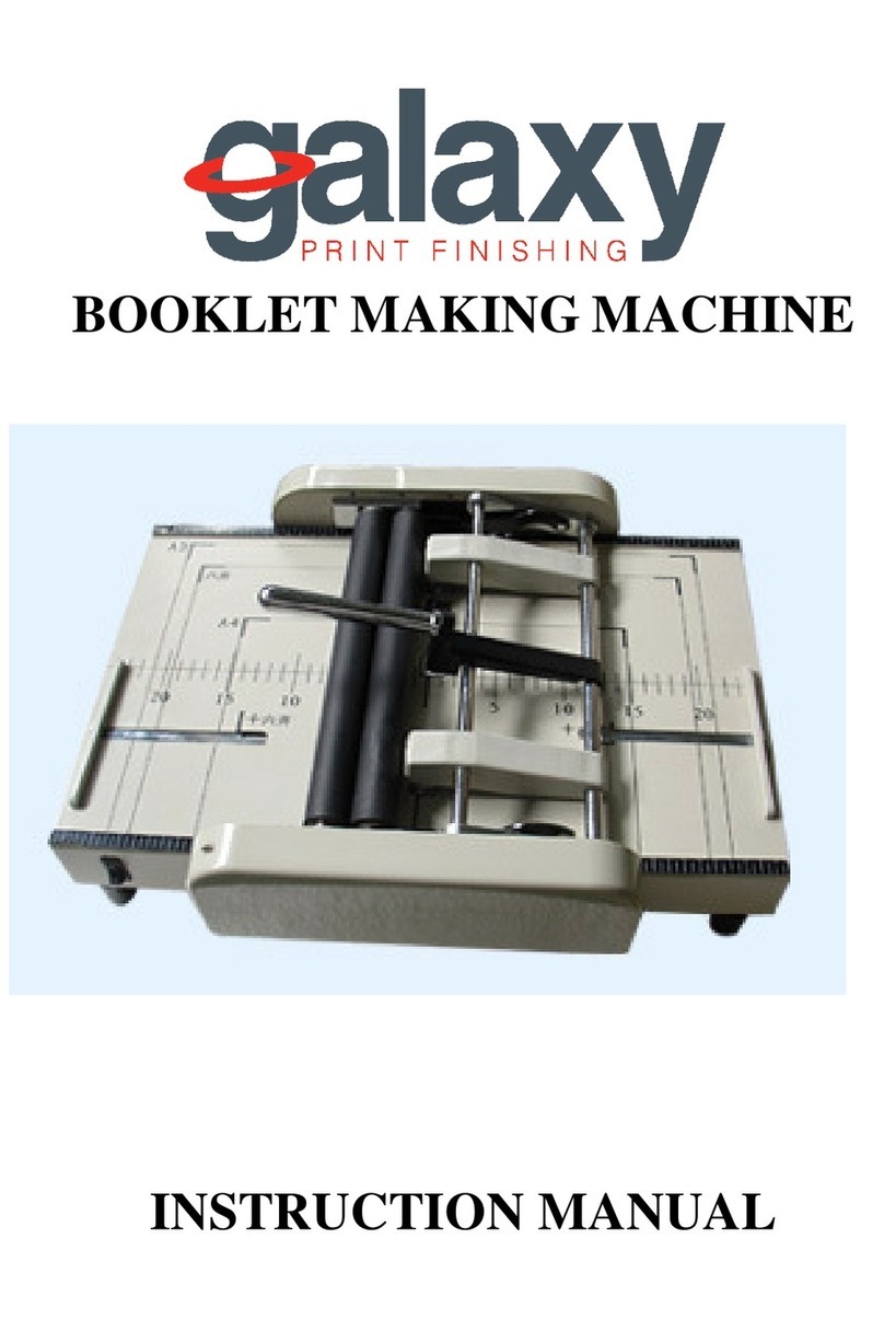
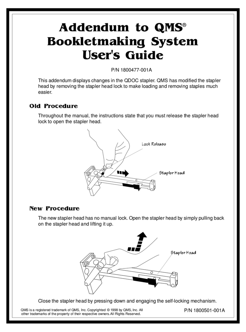
MyBinding GBC SignMaker 25 User manual

SignMaker 25 & 44
INSTALLATION &
OPERATION MANUAL
Document Number: 930-112 REV: - REV DATE: 10-4-04
©2004 GENERAL BINDING CORPORATION ALL RIGHTS RESERVED.
Do not duplicate without written permission.

Operating Instructions
i
SIGNMAKER 25/44
©2004 General Binding Corporation
TABLE OF CONTENTS
1.0 Safety 1-1
General 1-1
Electrical 1-1
2.0 Warranty 2-1
Limited 90-Day Warranty 2-1
3.0 Specifications 3-1
4.0 Pre-Installation and Installation 4-1
5.0 Feature Guide 5-1
A. POWER SWITCH: 5-1
B. FAN SWITCH: 5-1
C. CONTROL PANEL: 5-1
D. FEED TABLE: 5-2
E. SAFETY SHIELD: 5-2
F. TABLE INTERLOCK LATCH: 5-2
G. FEED GUIDE: 5-2
H.UPPER HEAT ROLLER: 5-3
I. IDLER BAR: 5-3
J. PULL ROLLERS: 5-3
K. CIRCUIT BREAKER: 5-3
L. FILM SHAFT: 5-3
M. LOCKING CORE ADAPTORS: 5-3
N. FILM WEB: 5-3
O. NIP POINT: 5-4
P. ROLLER PRESSURE HANDLE: 5-4
Q. TAKE UP ASSEMBLY: 5-4
R. FILM TENSION ADJUSTMENT: 5-4
6.0 Operation 6-1
Safety Shield Removal 6-2
Film Loading and Threading 6-2
Method Using Film Threading Card 6-3
Method For Tacking New Film to Existing Film 6-5
Mounting 6-6
Mounting and Overlamination 6-6
Decaling; PSA or Thermal film - Two Passes 6-7
Mounting Only 6-8
AccuShield™ Film 6-8
Running Foil 6-8
Film Alignment 6-9
Film Tension Adjustment 6-9
Clearing a Film Jam (Wrap-up) 6-9
7.0 Operator Maintenance 7-1
Caring For The GBC SignMaker Series Laminator 7-1
Trouble Shooting Guide 7-2
Lamination Guide 7-3

Operating Instructions
Page ii ©2004 General Binding Corporation
SIGNMAKER 25/44

Operating Instructions
iii
SIGNMAKER 25/44
©2004 General Binding Corporation
DISCLAIMER
The information in this publication is provided for reference and is believed
to be accurate and complete. GBC is not liable for errors in this publication
or for incidental or consequential damage in connection with the furnishing
or use of the information in this publication, including, but not limited to, any
implied warranty of fitness or merchantability for any particular use.
GBC reserves the right to make changes to this publication and to the products
described in it without notice. All specifications and information concerning
products are subject to change without notice.
Reference in this publication to information or products protected by copy-
right or patent does not convey any license under the rights of GBC or others.
GBC assumes no liability arising from infringements of patents or any other
rights of third parties.
This publication is copyrighted © 2004 by GBC. All rights reserved. The infor-
mation contained in this publication is proprietary and may not be reproduced,
stored, transmitted, or transferred, in whole or in part, in any form without the
prior and express written permission of GBC.

Operating Instructions
iv ©2004 General Binding Corporation
SIGNMAKER 25/44

Operating Instructions
Page 1-1
SIGNMAKER 25/44
©2004 General Binding Corporation
1.0 SAFETY
YOUR SAFETY AS WELL AS THE SAFETY OF OTHERS IS IMPORTANT
TO GBC. IN THIS INSTRUCTION MANUAL AND ON THE PRODUCT,
YOU WILL FIND IMPORTANT SAFETY MESSAGES REGARDING
THE PRODUCT. READ THESE MESSAGES CAREFULLY. READ
ALL OF THE INSTRUCTIONS AND SAVE THESE INSTRUCTIONS
FOR LATER USE.
THE SAFETY ALERT SYMBOL PRECEDES EACH SAFETY
MESSAGE IN THIS INSTRUCTION MANUAL. THE SYMBOL
INDICATES A POTENTIAL PERSONAL SAFETY HAZARD TO
YOU OR OTHERS, AS WELL AS PRODUCT OR PROPERTY
DAMAGE.
THE FOLLOWING WARNINGS ARE FOUND ON THE SignMaker:
THIS SAFETY MESSAGE MEANS THAT YOU COULD BE SERIOUSLY
HURT OR KILLED IF YOU OPEN THE PRODUCT AND EXPOSE YOUR-
SELF TO HAZARDOUS VOLTAGE.
THIS SAFETY MESSAGE MEANS THAT YOU COULD BE BURNED AND
YOUR FINGERS AND HANDS COULD BE TRAPPED AND CRUSHED IN
THE HOT ROLLERS. CLOTHING, JEWELRY AND LONG HAIR COULD
BE CAUGHT IN THE ROLLERS AND PULL YOU INTO THEM.
ADVERTENCIA
!
Riesgo de choque
eléctrico
No abra:
Adentro no hay
piezas reparables
por el usuario.
Mantenimiento
solamente por
personal
calificado
ATTENTION
!
Risque de
secousse
électrique.
Ne pas ouvrir.
Pas de pièces
réparables par
l'utilisateur.
Entretien
seulement par
personnel qualifié.
WARNING
!
Electrical shock
hazard.
Do not open.
No user
serviceable
parts inside.
Refer servicing to
qualified service
personnel.
ADVERTENCIA
!ATTENTION
!CAUTION
!
RODILLOS
CALIENTES.
PUNTO DE
PINCHAMIENTO.
Mantener manos y
ropa a distancia.
ROULEAUX
CHAUDS.
POINT DE
PINCEMENT.
Tenir mains et
vêtements à l'écart.
HOT ROLLS.
PINCH POINT.
Keep hands and
clothing away.
WARNING: DO NOT CONNECT THE SignMaker SERIES
LAMINATOR TO AN ELECTRICAL SUPPLY OR ATTEMPT TO
OPERATE THE LAMINATOR UNTIL YOU HAVE COMPLETELY
READ THESE INSTRUCTIONS. MAINTAIN THESE INSTRUC-
TIONS IN A CONVENIENT LOCATION FOR FUTURE REFER-
ENCE.
WARNING: TO GUARD AGAINST INJURY, THE FOLLOWING
SAFETY PRECAUTIONS MUST BE OBSERVED IN THE
INSTALLATION AND USE OF THE LAMINATOR.
General
Keep hands, long hair, loose clothing, and articles such as necklaces or
ties away from the front of the heat and pull rollers to avoid entanglement
and entrapment.
The heat rollers can reach temperatures over 300° F. Avoid contact with
the heat rollers during operation or shortly after power has been removed
from the laminator.
Do not use the laminator for other than its intended purpose.
Do not place the laminator on an unstable cart, stand or table. An unstable
surface may cause the laminator to fall resulting in serious bodily injury.
Avoid quick stops, excessive force and uneven floor surfaces when moving
the laminator on a cart or stand.
Do not defeat or remove electrical and mechanical safety equipment such
as interlocks, shields and guards.
Do not insert objects unsuitable for lamination or expose the equipment
to liquids.
Turn off machine when not in use for an extended period of time.
Electrical
The laminator should be connected only to a source of power as indicated
in these instructions and on the serial plate located on the rear of the
laminator. Contact an electrician should the attachment plug provided
with the laminator not match the receptacles at your location.
CAUTION: The receptacle must be located near the equipment
and easily accessible.
Disconnect the attachment plug from the receptacle to which it is
connected and keep the power supply cord in your possession while
moving the laminator.
Do not operate the laminator with a damaged power supply cord or attach-
ment plug, upon occurrence of a malfunction, or after the laminator has
been damaged. Contact GBC’s Technical Service Department or your
dealer/distributor for assistance.

Operating Instructions
Page 1-2 ©2004 General Binding Corporation
SIGNMAKER 25/44
WARNING: Do not attempt to service or repair the laminator.
Disconnect the plug from the receptacle and contact GBC’s Technical
Department or your dealer/distributor when one or more of the following
has occurred.
- The power supply cord or attachment plug is damaged.
- Liquid has been spilled into the laminator.
- The laminator is malfunctioning after being mishandled.
- The laminator does not operate as described in these instructions.

Operating Instructions
Page 2-1
SIGNMAKER 25/44
©2004 General Binding Corporation
WARRANTY
2.0 WARRANTY
Limited 90-Day Warranty
GBC warrants to the original purchaser for a period of
ninety days on labor and one year on parts after installation
that this laminator is free from defects in workmanship and
material under normal use and service. GBC’s obligation
under this limited warranty is limited to replacement or
repair, at GBC’s option, of any part found defective by
GBC without charge for material or labor.
THIS LIMITED WARRANTY IS IN LIEU OF ALL
OTHER WARRANTIES EXPRESSED OR IMPLIED.
WARRANTIES OF MERCHANTABILITY OR FITNESS
FOR A PARTICULAR PURPOSE ARE EXPRESSLY
EXCLUDED. ANY REPRESENTATIONS OR PROM-
ISES INCONSISTENT WITH, OR IN ADDITION TO,
THIS LIMITED WARRANTY ARE UNAUTHORIZED
AND SHALL NOT BE BINDING UPON GBC. IN NO
EVENT SHALL GBC BE LIABLE FOR ANY SPECIAL,
INCIDENTAL, OR CONSEQUENTIAL DAMAGES,
WHETHER OR NOT FORESEEABLE.
This limited warranty shall be void if the laminator has
been misused; mishandled; damaged by negligence,
by accident, during shipment, or due to exposure to
extreme conditions; repaired, altered, moved, or installed
by anyone other than GBC or its authorized agents; or if
incompatible film was used. GBC’s obligation under this
limited warranty does not include routine maintenance,
cleaning, adjustment, normal cosmetic or mechanical
wear, or freight charges.
Without limiting the generality of the previous paragraph,
GBC’s obligation under this limited warranty does not
include:
1. Damage to the rollers caused by knives, razors, or
other sharp tools; by any foreign objects falling into the
working area of the laminator; or by cleaning the laminator
with solutions or materials that harm its surfaces;
2. Damage caused by adhesives; nor
3. Damage caused by lifting, tilting or attempting to
position the laminator other than rolling it on its castors
across even surfaces.
FOR EUROPEAN UNION RESIDENTS ONLY: This guar-
antee does not affect the legal rights which consumers
have under applicable national legislation governing the
sale of consumer goods.
The information in this publication is provided for refer-
ence and is believed to be accurate and complete. GBC
is not liable for errors in this publication or for incidental or
consequential damage in connection with the furnishing
or use of the information in this publication, including,
but not limited to, any implied warranty of fitness or
merchantability for any particular use.
GBC reserves the right to make changes to this publica-
tion and to the products described in it without notice.
All specifications and information concerning products
are subject to change without notice.
Reference in this publication to information or products
protected by copyright or patent does not convey any
license under the rights of GBC or others. GBC assumes
no liability arising from infringements of patents or any
other rights of third parties.
This publication is copyrighted © 2004 by GBC. All rights
reserved. The information contained in this publica-
tion is proprietary and may not be reproduced, stored,
transmitted, or transferred, in whole or in part, in any
form without the prior and express written permission
of GBC.
Operating Instructions
Page 2-2 ©2004 General Binding Corporation
SIGNMAKER 25/44


Operating Instructions
Page 3-2 ©2004 General Binding Corporation
SIGNMAKER 25/44

Operating Instructions
Page 4-1
SIGNMAKER 25/44
©2004 General Binding Corporation
4.0 PRE-INSTALLATION AND
INSTALLATION
Perform only the routine maintenance procedures referred to in these
instructions.
WARNING: Do not attempt to service or repair the laminator.
Disconnect the plug from the receptacle and contact GBC’s Technical
Department or your dealer/distributor when one or more of the following
has occurred.
- The power supply cord or attachment plug is damaged.
- Liquid has been spilled into the laminator.
- The laminator is malfunctioning after being mishandled.
- The laminator does not operate as described in these instructions.
1. Shipping damage should be brought to the immediate attention
of the delivering carrier.
2. Place the SignMaker on a stable flat surface capable of supporting
the weight of the machine and any materials. The surface should
be at least 30 inches high to assure comfortable positioning during
operation. All four rubber support feet should be positioned completely
on the supporting surface. The supporting surface may also be large
enough to hold the material to be laminated.
3. The laminator should be located so that exiting film drops freely to
the floor. Accumulation of laminate immediately behind the laminator
as it exits the equipment may cause the film to wrap around the pull
rollers, resulting in a “jammed” condition.
4. Avoid locating the laminator near sources of heat or cold. Avoid locating
the laminator in the direct path of forced, heated or cooled air.
5. Connect the attachment plug provided with the laminator to a suitably
grounded outlet only. Avoid connecting other equipment to the
same branch circuit to which the laminator is connected, as this
may result in nuisance tripping of circuit breakers or blowing
fuses.

Operating Instructions
Page 4-2 ©2004 General Binding Corporation
SIGNMAKER 25/44

Operating Instructions
Page 5-1
SIGNMAKER 25/44
©2004 General Binding Corporation
5.0 FEATURE GUIDE
A. POWER SWITCH:
Fig.1.
Located at the back of the machine, the power switch applies power
to the laminator. The "LED" display panel will illuminate when position
marked “l” is pushed. The off position, marked “O”, removes power from
the laminator.
B. FAN SWITCH:
Fig. 1.
C. CONTROL PANEL:
Fig. 2
Display:
"READY": Indicates when the laminator has sufficient heat. It flashes if
heat is out of range.
"SPEED": Indicates the speed setting of the motor.
"TEMPERATURE": Displays the programmed temperature setting in
either Fahrenheit or Celsius.
Functions:
"HOT": When pressed, automatically sets the temperature to 230 ºF
(110 ºC).
"COLD" : When pressed, removes power to the heaters for cold
lamination.
"RUN": Activates rollers for normal operation.
"STOP": When pressed, stops the rotation of the rollers.
"REV": Reverses roller movement to clear jams and wrap-ups.
"MEAS": Used to read the current temperature of the rollers.
"TEMP" ( ): Overrides the preset temperature, increasing to the
desired setting.
"TEMP" ( ): Overrides the preset temperature, decreasing to the
desired setting.
"SPEE D" ( ): When pressed, increases speed to the desired
setting.
( ): When pressed, decreasing speed to the desired
setting.
Fig. 2
Fig. 2
"SPEE D"
The fan switch is located in the back of the machine. Power is applied
to the fans when the switch is set to the “ I ” position and the “RUN”
switch is pressed. The off position marked “O” removes power from
the fans.

Operating Instructions
Page 5-2 ©2004 General Binding Corporation
SIGNMAKER 25/44
D. FEED TABLE:
The Feed Table, Fig 3, is used to position items for lamination. The lami-
nator will operate only when the Feed Table and Feed Table Latch
are properly installed.
E. SAFETY SHIELD:
Prevents entanglement, entrapment and inadvertent contact with the
heat rollers. The laminator will operate only when the Safety Shield is
located in the fully locked position. Power to the motor is removed
when the shield is removed.
F. TABLE INTERLOCK LATCH:
Used to lock the Feed Table into position and activate an interlock switch.
The interlock latch is located on the left underside of the Feed Table, (Fig
3). The table cannot be removed without retracting the latch to the
right while lifting the table upwards and away from the laminator.
The laminator will not operate when the table is removed and/or the
interlock latch is retracted.
G. FEED GUIDE:
The Feed Guide, Fig 3, permits alignment of the item(s) to be laminated.
To position the adjustable guide, loosen the knob on the top of the guide,
slide it to the desired position and tighten the knob to secure the Feed
Guide in place. The Feed Guide is used to keep longer items straight.
The Feed Guide may also be used to feed smaller items side by side by
positioning the guide towards the center of the Feed Table and placing
smaller items against each side of the Feed Guide as they are being
introduced into the nip point of the heat rollers.
Fig. 3

Operating Instructions
Page 5-3
SIGNMAKER 25/44
©2004 General Binding Corporation
H.UPPER HEAT ROLLER:
Silicone rubber coated steel tubes heat the laminating film and compress
the heated film to the items being laminated. Heat is provided by an
internal heating element in the top main roll. The main rollers are motor
loading new film (Fig 4).
I. IDLER BAR:
The idler bars, located near each supply roll, are used to direct the film
to the main rollers. The bottom Idler Bar is movable to ease film loading
(Fig 4).
J. PULL ROLLERS:
The pull rollers, located at the back of the laminator, are motor driven.
They simultaneously pull the film and improve the quality of the laminated
item (Fig 4).
K. CIRCUIT BREAKER:
Electrical safety device, located on the back of the laminator near the
power cord, can be reset by the operator if tripped (Fig 5).
WARNING: If the breaker trips a second time after being reset,
contact your local GBC Technical Representative or dealer/distributor
for assistance.
L. FILM SHAFT:
The film shaft holds the film supply on the machine, (Fig 6).
M. LOCKING CORE ADAPTORS:
Hold and lock the rolls of film on the shafts to prevent side to side shifting,
(Fig 6).
N. FILM WEB:
Laminating film loaded into the machine.
Fig. 4
Fig. 6
Fig. 5
( Not Shown )
driven for ease of


Operating Instructions
Page 6-1
SIGNMAKER 25/44
©2004 General Binding Corporation
OPERATING INSTRUCTIONS
6.0 OPERATION
1. Turn the laminator on (I) at the main power switch located at the back
of the machine (Fig 10).
2.
CAUTION: Make sure the safety shield and feed tray are in their
proper positions.
3. The laminator will automatically default to the "COLD" setting which
is used for PSA (pressure sensitive adhesive) film. For thermal film
press "HOT", when pressed, automatically sets the temperature to
230 ºF (110 ºC).
4. Do not begin laminating until the "READY" LED illuminates. The
normal warm-up time is approximately 10 minutes.
5. Position the roller gap handle to correspond to the gauge of film
laminated.
6. Position the item(s) to be laminated on the Feed Table.
7. Press "RUN". The rollers will begin to turn. Wait for the heat line to
disappear, then push the item(s) into the nip point of the heat rollers.
Additional items can be laminated without stopping and starting the
laminator.
8. Should a jam occur (wrap-up), press "STOP". Refer to the section
CLEARING A FILM JAM for specific instructions.
9. Stop the laminator when all of the items have completely exited the
rear of the machine.
10. Allow the laminator to remain powered if it is anticipated that it will be
used within a short period of time.
Fig. 10

Operating Instructions
Page 6-2 ©2004 General Binding Corporation
SIGNMAKER 25/44
Safety Shield Removal
1. Lift the shield off.
2. To install reverse the step from above.
FEED TABLE REMOVAL
Refer to Fig 11 and follow the procedures to remove the feed table:
1. Slide the Feed Table latch to the right.
2. Lift the table upwards and away from the laminator.
Reverse this process to re-install the shield.
Film Loading and Threading
Refer to the film threading diagram for the application you are running for
an illustration of properly threading film.
The SignMaker 25 uses Poly-In film. Poly-In means the adhesive side
of the film is on the inside of the web (Fig 12). The SignMaker 44 uses
Poly-Out Thermal films and Poly-In PSA films. The shiny side of clear
film must contact the heat rollers. The dull side of the film contains the
adhesive. Use extreme caution when loading delustered (matte) film as
both sides appear dull.
The top and bottom rolls of laminating film must be of the same width and
be present simultaneously. A small amount of adhesive will “squeeze out”
during lamination. Hardened adhesive deposits can damage the main
rollers. To avoid any damage, rotate the rollers at slowest speed if the
"READY" LED is not illuminated. Refer to the section entitled CARING
FOR THE SignMaker SERIES LAMINATOR for instructions regarding
removal of the accumulated adhesive.
Adhesive will deposit on the rollers if:
- Only one roll is used.
- Different widths of rolls are loaded together.
- Either roll is loaded adhesive side against a heat roller.
- One or both rolls of film are allowed to run completely off its core.
Always change the top and bottom supply rolls at the same time. Near the
end of each roll of GBC laminating film is a label stating “Warning-End of
Roll”. The appearance of this label on either the top or bottom roll requires
that new rolls of film be installed as soon as the item presently being
laminated completely exits the rear of the laminator. Do not introduce any
additional items into the laminator when the warning label is visible.
Fig. 11
POLY-IN
POLY-OUT
Poly-in
Adhesive
surface
Polyester surface
Poly-out
Adhesive
surface
Polyester surface
Fig. 12
This manual suits for next models
1
Table of contents
Other MyBinding Booklet Maker manuals

MyBinding
MyBinding Standard M2 User manual

MyBinding
MyBinding MBM 87M User manual

MyBinding
MyBinding Plockmatic BM 200 User manual

MyBinding
MyBinding BM 61 User manual

MyBinding
MyBinding Formax Square IT User manual

MyBinding
MyBinding MBM 87M User manual

MyBinding
MyBinding Plockmatic BM 200 User manual

MyBinding
MyBinding MBM 87M User manual