MBM iBOOKLET User manual

MBM
iBOOKLET
Oct. 24, 2016
MBM Corporation
Ver.A_1
Service Manual

2
Introduction
Thank you for purchasing the iBOOKLET.
The iBOOKLET is a tabletop booklet maker.
Its major features include:
- Comfort in operation supported by touch-type switches.
- Support for two clinching methods to make a wide variety of booklets
- Automated or manual booklet making is possible only by selecting paper size.
Read this manual carefully to ensure the product is handled and used under the best
condition
Table of Contents
1. Troubleshooting...................................................................................................................5
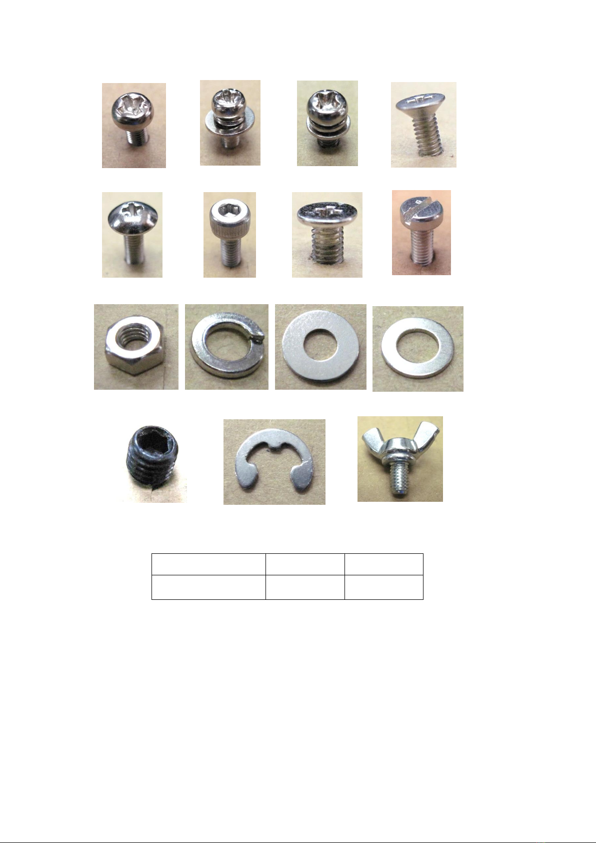
2. Descriptions of Different Types of Screws ..........................................................................7
3. Replacing Components ........................................................................................................8
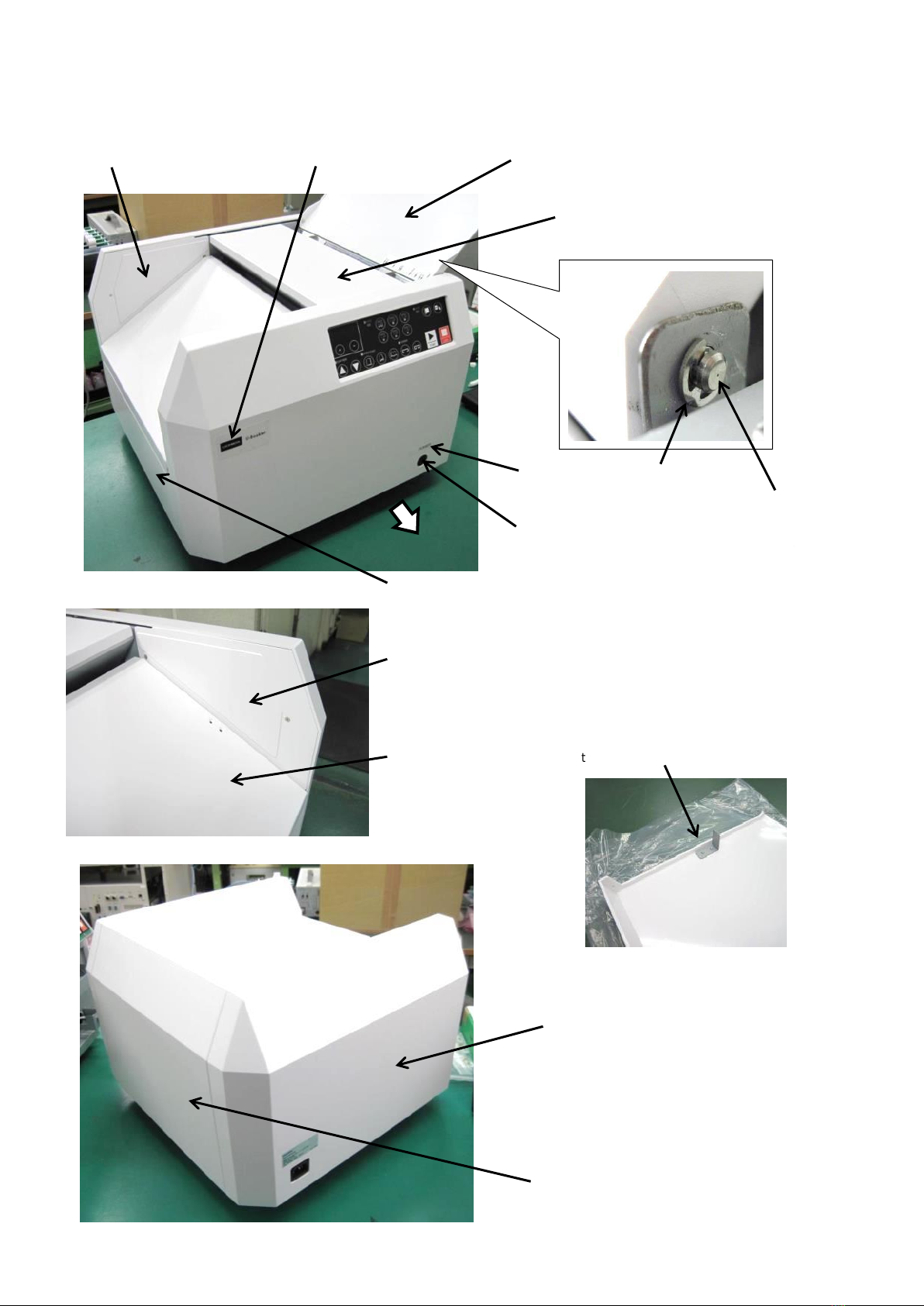
3-1 Replacing the Outer Covers .........................................................................................8
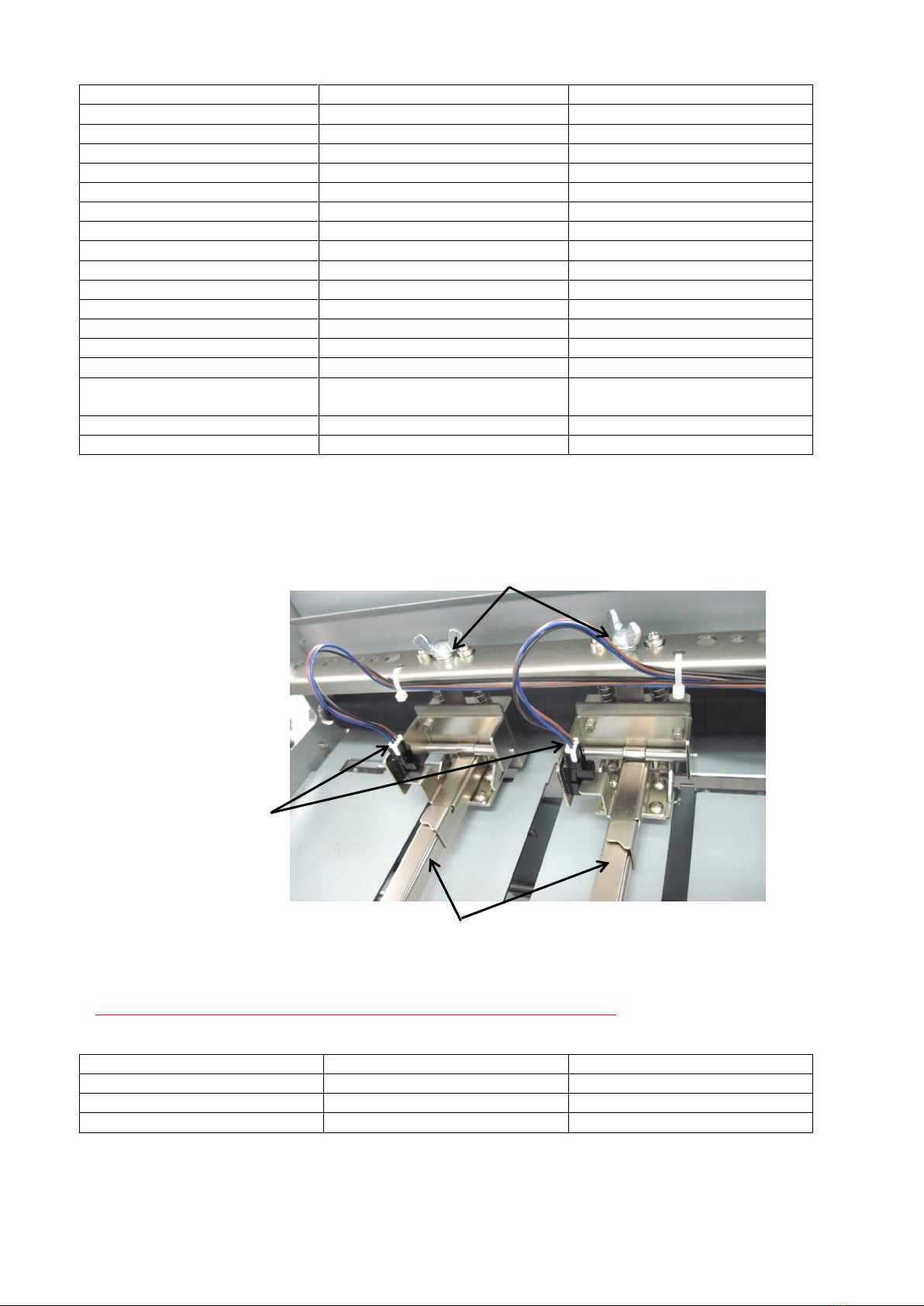
3-2 Replacing the Stapler Units..........................................................................................9
3-3 Replacing the Knock Pin ............................................................................................10
3-4 Replacing the Staple Level Sensor............................................................................10
3-5 Dissembling and Reassembling a Stapler Unit (Removing the staples that are stuck)
............................................................................................................................................11
3-6 Adjusting the Stapler Unit Head.................................................................................12
3-7 Replacing and Cleaning Clincher Pieces...................................................................14
3-8 Adjusting the Clincher Position .................................................................................15
3-9 Adjusting the Cushion Piece......................................................................................16
3-10 Adjusting the Belt Tension.......................................................................................18
3-11 Replacing the Circuit Board .....................................................................................20
3-12 Replacing the Control Panel.....................................................................................21
3-13 Replacing a Joint Arm...............................................................................................22
3-14 Replacing the Power Supply Unit.............................................................................24
3-15 Replacing the Inlet ....................................................................................................25
3-16 Replacing the Switch Unit.........................................................................................26
3-17 Replacing the Cover Switch .....................................................................................27
3-18 Replacing the Paper Sensor.....................................................................................29
3-19 Replacing Sensors....................................................................................................31
3-20 Replacing the Stapler Motor.....................................................................................33
3-21 Replacing the Wind-Up Motor ..................................................................................35
3-22 Replacing the Clincher Motor...................................................................................37
3-23 Replacing the Paper Feed Motor..............................................................................38
3-24 Replacing the Timing Belt.........................................................................................40
3-25 Detaching the Cover for Removing Paper...............................................................42

3
3-26 Replacing the Wind-Up Roller..................................................................................43
4. Adjusting the Program ......................................................................................................46
4-1 Maintenance Mode......................................................................................................46
4-2 Installing Program Writing Software..........................................................................48
4-3 Upgrading the Program ..............................................................................................52

4
Safety Precautions
*The repair of a product that is damaged or malfunctions because of failure to follow the
instructions in this manual may not be free of charge, even during the warranty period.
Notes on Installation
Notes on Power Supply
Notes on Use
Warning
Do not install the product at a place where there is alcohol, thinner or other
volatile substances, or an open flame.
Doing so may cause fire or electric shock.
Caution
Do not install or store the product at an unstable place or at a place prone to
vibrations from other machinery.
Doing so may cause the product to drop or fall over, resulting in injury.
When lifting or transporting the product, use both hands to hold the product
from the rear.
Lifting the product from front or side may result in poor weight balance, causing you to
fall or become injured.
Warning
Connect the power cord to a grounded outlet.
Failure to do so may result in the malfunction of the protection circuit and cause an
electric shock.
Do not connect or disconnect the power plug with wet hands.
Doing so may cause electric shock.
Do not use any voltage other than specified by the machinery.
Doing so may cause an electric shock or fire.
Do not use a damaged power cord.
Do not process the power cord.
Do not put anything heavy on the power cord.
Keep the AC inlet at least 8 cm from the wall.
Failure to follow these instructions could cause an electric shock or fire.
Warning
Do not use the product when it is acting abnormally, such as emitting smoke,
foul odors, or noises.
Doing so may cause an electric shock or fire. Power it off immediately and disconnect
the power plug from the outlet.
Do not disassemble or modify this product unless otherwise specified to do so
in this manual.
Doing so may cause an electric shock or fire.
Do not use the product when there is foreign matter, water, or another form of
liquid inside.
Doing so may cause an electric shock or fire.
Caution
Do not mount anything on the product or place anything heavy on it.
Doing so may cause the product to fall or break, resulting in injury.
If the product is not to be used for a long time, be sure to disconnect the power
cord from the outlet for safety purposes.
Do not use needles other than those that are recommended.
Doing so may cause some staples to become stuck.
Do not load a number of sheets that exceeds the specified limit.
Do not use any thick, broken, or old paper.
Do not feed any paper from a high position.
Do not push paper forcefully.
Doing so may hamper proper bookbinding.

5
1. Troubleshooting
List of Items
Item
Remedial Measures and Reference
1. Trouble with Staples
(1) Staples are stuck.
1. Disassemble the product and remove the staples.
-> 3-5 Dissembling and Reassembling Stapler Units
2. If staples repeatedly become stuck, adjust the
product.
-> 3-6. Adjusting the Stapler Unit Head
(2) No staple can be clinched.
1.Adjust the stapler unit.
-> 3-6. Adjusting the Stapler Unit Head
2. Replacement of the knock pin is recommended.
-> 3-3. Replacing the Knock Pin
(3) Staples do not bend.
1. If cleaning does not clear the problem,
replacement is recommended.
-> 3-7. Replacing and Cleaning the Clincher Piece
(4) The leg parts of a staple differ in
shape.
1.Adjust the position of the joint arm.
-> 3-13. Replacing the JointArm
(5) Staples cannot be clinched properly.
1.Adjust the stapler unit.
-> 3-6. Adjusting the Stapler Unit Head
2.Adjust the clincher.
-> 3-8. Adjusting the Clincher Position
(6) E02 is not displayed when staples are
running short.
E02 is displayed when the product has
sufficient staples.
1. Replacement of the sensor is recommended.
-> 3-4. Replacing the Staple Level Sensor.*
2. Trouble with Paper
(1) Paper is slowly fed.
1.Adjust the tension of the belt.
-> 3-10.Adjusting the Belt Tension
(2) Paper is folded at an inappropriate
position.
1.Adjust the tension of the belt.
-> 3-10.Adjusting the Belt Tension
2.Adjust the folding position.
-> 4-1. Maintenance Mode
3. Replacement of the cushion piece is
recommended.
-> 3-9. Replacing the Cushion Piece
(3) Paper is stuck and cannot be taken
out.
1. Detach the cover to remove the paper.
-> 3-25. Detaching the Cover for Removing Paper
(4) The paper folding position is not
matched with the staple position.
1.Adjust the staple position.
-> 4-1. Maintenance Mode
2.Adjust the tension of the belt.
-> 3-10.Adjust the Belt Tension
3. Replacement of the cushion piece is
recommended.
-> 3-9. Replacing the Cushion Piece
3. Errors
(1) E01 is displayed.
1. Close the upper cover L.
2. Check if the metal plate on the cover side is
deformed.
-> 3-1. Replacing the Outer Covers
3. Check the cover switch.
-> 3-17. Replacing the Cover Switch
If the adjustment or replacement of a component is required, refer to
the Service Manual and ensure that it will be performed by a qualified
person.

6
(2) E02 is displayed.
1. Refill staples.
2. Check the staple level sensor.
-> 3-4. Replacing the Staple Level Sensor*
(3) E03 is displayed.
1. Remove paper.
2. Check the paper sensor.
-> 3-18. Replacing the Paper Sensor*
(4) E04 is displayed.
1. Press the START key to see if the product is
restored.
2. Replacement of the circuit board is recommended.
-> 3-11. Replacing the Circuit Board
3-12. Replacing the Control Panel
(5) E10 is displayed.
After the product is powered on, 888
remains displayed.
1. Power the product off, unplug the AC cable and
after a while, power it on again.
2. If all the motors are not operational, check the
cover switch.
-> 3-17. Replacing the Cover Switch
3. Check if there is a plate between the push-up
(upper) sensor and the stapler (lower) sensor.
-> 3-19. Replacing Sensors*
4. If the clincher motor does not operate when the
clincher is in the loop mode, check the motor.
-> 3-22. Replacing the Clincher Motor
5. If the clincher moves beyond its lower limit, check
the clincher sensor.
-> 3-19. Replacing Sensors*
6. If the paper feed motor is not operational, check
the paper sensor and the paper feed sensor.
-> 3-18. Replacing the Paper Sensor*
3-23 Replacing the Paper Feed Sensor
3-20. Replacing the Stapler Motor
7. If the paper stopper moves beyond its lower limit,
check the paper feed sensor.
-> 3-18. Replacing the Paper Sensor*
8. Check the following components.
-> 3-21. Replacing the Wind-Up Motor
3-11. Replacing the Circuit Board
* If the replacement of the sensor does not fix the problem, also check the condition of the sensor
cable.

7
2. Descriptions of Different Types of Screws
Shapes of Different Types of Screws
Screw Fastening Torque
M3
M4
Fastening Torque
[cN·m]
50
1. 30
* If the torque is specified in the steps for replacement, follow the specification.
[Notes]
- The photos merely represent examples of the shapes, the actual diameter, length, surface finish
and others vary depending on individual screws.
Notation: [Qty.] - [Form] [Diameter or Nominal Diameter] x [Length] e.g. 4 - M3 x 10, SW4
- If any locked screw becomes unfastened, remove the screw lock and apply the screw lock again
at the time of reassembly. (The Threebond 1401B is recommended.)
- Prior to unfastening any position-adjusted screw, record its original position to ensure that it is at
refastened at the original position in the reassembly process.
Small Pan Head
Screw (M)
Flat Washer
(medium) (W)
Washer-Equipped
Screw (small) (NC)
Wing Bolt (WB)
Hexagonal Nut
(N)
Spring Washer
(SW)
Small Flat Washer
(LW)
(W)
Washer-Equipped Screw
(medium) (NB)
Set Screw (SS)
Inner Hexagonal Hole
Screw (HS)
Truss Head
Screw (TR)
Small Flat Head
Screw (F)
Small Slotted Flat
Head Screw (SF)
Small Countersunk
Head Screw (S)
E-Shaped Ring (E)

8
3. Replacing Components
3-1 Replacing the Outer Covers
421 [Sensor Plate]
2-S3x6
(Be careful about the orientation of
the plate when it is attached.)
Assembling the upper cover L
401 [Rear Cover]
3-NB3x8
405 [Side Cover R]
3-NB3x8
400 [Front Cover]
3-NB3x8
407 [Guide Cover R]
504 [Paper Size Sticker]
403 [Upper Cover R]
(Trace the injection through the gate on the right side)
424 [Inside Cover R]
2-S3x6
406 [Side Cover L]
3-NB3x8
Front
504
[Power Switch Sticker]
3-NB3x8
503 [Company Logo Sticker]
423 [Inside Cover F]
2-S3x6
404
[Upper Cover L]
2 pieces of 425 [PIN]
2 pieces of E3
(Fix the E-shaped ring from the
outside.)
2-E3
2 pieces
of 425
[PIN]
2個

9
List of Components
No.
Name
Qty.
400
Front Cover
1
401
Rear Cover
1
403
Upper Cover R
1
404
Upper Cover L
1
405
Side Cover R
1
406
Side Cover L
1
407
Guide Cover R
1
423
Inside Cover F
1
424
Inside Cover R
1
421
Sensor Plate
1
425
PIN
4
504
Power Switch Sticker
1
505
Paper Size Sticker
1
503
Company Logo Sticker
1
NB3x6
Washer-Equipped Screw
(medium)
12
S3x6
Small Countersunk Head Screw
6
E3
E-Shaped Ring
4
3-2 Replacing the Stapler Units
1. Remove the two cable assemblies (1). Then, while holding the stapler unit, remove the wing bolt.
2. After the replacement, take the reverse steps to reassemble the product.
When inserting a connector to the sensor, be careful not to bend the pin.
List of Components
No.
Name
Qty.
104
CableAssy (1)
2
01-001
Stapler Unit
2
WB5x10
Wing Bolt
2
2-WB5x10
2 pieces of 01-001[Stapler Unit]
2 pieces of 104 [Cable
Assy (1)]

10
3-3 Replacing the Knock Pin
1. Following the steps in 3.2 Replacing the Stapler Units, remove the stapler unit.
2. Remove the knock pin.
3. After the replacement,
take the reverse steps to reassemble the product.
List of Components
No.
Name
Qty.
01-001
Stapler Unit
1
225
Knock Pin
1
3-4 Replacing the Staple Level Sensor
1. Following the steps in 3.2 Replacing the Stapler Units, remove the stapler unit.
2. Remove the sensor.
3. After the replacement, take the reverse steps to reassemble the product.
When inserting the connector into the sensor, be careful not to bend the pin.
List of Components
No.
Name
Qty.
01-001
Stapler Unit
1
102
Sensor
1
01-001
[Stapler Unit]
225 [Knock Pin]
Staple Level Sensor
(102 [Sensor])
01-001
[Stapler Unit]

11
3-5 Dissembling and Reassembling a Stapler Unit (Removing the staples that are stuck)
1. Following the steps in 3-4 Replacing the Staple Level Sensor, remove the sensor.
2. Remove the four hexagonal hole screws.
3. After disassembly, remove all the staples.
4. After the removal, take the reverse steps to reassemble the product.
When inserting the connector into the sensor, be careful not to bend the pin.
Refer to 3.6 Adjusting the Stapler Unit Head.
List of Components
No.
Name
Qty.
01-001
Stapler Unit
1
221
Base Block
1
226
Plate
1
HS3x6
Inner Hexagonal Hole Screw
4
4-HS3x6
226
[Plate]
4-HS3x6
221 [Base Block]

12
3-6 Adjusting the Stapler Unit Head
1. Following the steps in 3-4 Replacing the Staple Level Sensor, remove the sensor.
2. Unfasten the small flat head screw to loosen the tension spring inside, and then insert the knock
pin from the opposite site.
3. Catch the slider on the upper part of the rail.
4. Unfasten four screws and adjust the rail position to ensure that the left part space and the right
part space of the knock pin are evenly inserted. Fix the rail in the state in which it is not forced
downwards but naturally placed.
(Check that the inserted knock pins are not shaky and can be moved smoothly.)
F3x12
225 [Knock Pin]
229 [Rail]
Adjust the rail to make sure that the left
part and the right part of the knock pin
seen from the gaps are even.
4-TR3x4
232 [Slider]
229 [Rail]

13
5. After the adjustment, take the reverse steps to reassemble the product.
Creation of a jig from a wire will make it easy to attach the slider tension spring.
List of Components
No.
Name
Qty.
102
Sensor
1
225
Knock Pin
1
232
Slider
1
229
Rail
1
F3x12
Small Flat Head Screw
1
TR3x4
Small Truss Head Screw
4
An example of a jig
Fasten the small flat head screw to the half
of the depth, and catch the spring using the
jig.
Jig

14
3-7 Replacing and Cleaning Clincher Pieces
<Replacing Clincher Pieces>
1. Power the product on and switch the clincher mode to Loop. Then power the product off.
2. Unfasten the screws to remove pieces.
3. After the replacement, take the reverse steps to reassemble the product.
After the replacement, perform a clinching trial. If there is any problem with the shape of the
staple, reattach the piece in the opposite direction.
<Cleaning Clincher Pieces>
Clean the depressed part of the piece with a swab or a soft cloth.
List of Components
No.
Name
Qty.
01-005
Piece
5
S3x4
Small Countersunk Head Screw
10
5 pieces of 275
5 pieces of 2-
S3x4
Reverse the orientation and reattach the piece.

15
3-8 Adjusting the Clincher Position
1. Following the steps in 3-1 Replacing the Outer Covers, remove the front cover and the rear cover.
2. Unfasten four screws to remove the reinforcement S. (Perform the same process on the rear
side.)
3. Loosen the hexagonal hole screws and three screws without detaching them. Then move the
upper screw positions to adjust the front-rear position of the clincher. Next, refasten the screws.
Perform the same process on the opposite site as well.
413 [Reinforcement S]
4-NC3x6
HS4x12
(Keep it loose until
the adjustment is
finished.)
3-M4x8
The front-rear position is
adjusted at the position of
this screw.

16
4. Power the product on and conduct a clinching trial to check the status of the staple. Repeat Step
3 until the staple is properly clinched.
After completion of the adjustment, refasten the hexagonal hole screws.
Note that fastening them too tightly can deform the metal plate.
5. After the adjustment, take the reverse steps to reassemble the product.
List of Components
No.
Name
Qty.
413
Reinforcement S
2
NC3x6
Washer-Equipped Screw
(small)
8
M4x8
Small Pan Head Screw
6
HS4x12
Inner Hexagonal Hole Screw
2
3-9 Adjusting the Cushion Piece
1. Following the steps in 3-1 Replacing the Outer Covers, remove the side cover L.
2. Unfasten four screws to remove the main unit bottom plate.
Adjusting the front-rear position of
the clincher piece
When the piece is closer to
the rear end
When the piece is closer to
the front end
When the piece is at the
correct position
Paper
Insertion
Direction
206 [Main Unit
Bottom Plate]
4-M4x8

17
3. Unfasten the screws on the back side of the paper feeder to remove the cushion piece.
4. After the adjustment, take the reverse steps to reassemble the product.
After fastening the cushion piece with a screw, pull the timing belt while holding the paper feeder to
check if the cushion piece moves smoothly.
List of Components
No.
Name
Qty.
206
Main Unit Bottom Plate
1
299
Timing Belt
1
426
Cushion Piece
1
427
Spring
1
429
Spacer
1
430
Washer
1
M4x8
Small Pan Head Screw
4
F3x12
Small Flat Head Screw
1
426 [Cushion Piece]
F3x12
426 [Cushion Piece]
F3x12
Catch the spring on
this screw.
Fasten F3x12 while pulling the timing belt to ensure that the
cushion piece is movable and attach a screw lock.
299 [Timing Belt]
429 [Spacer]
F3x12
430 [Washer]
427 [Spring]
430 [Washer]
(Fix along the
metal plate on the
right.)

18
3-10 Adjusting the Belt Tension
1. Following the steps in 3-1 Replacing the Outer Covers, remove the front cover, the rear cover,
the side cover L and the side cover R.
2. Unfasten three screws to remove the lower bracket. (Perform the same process on the opposite
side.)
3. Unfasten four screws to remove the main unit bottom plate.
4. Unfasten four screws to remove the stay. (Perform the same process on the opposite side.)
206 [Main Unit Bottom Plate], 4-M4x8
411 [Lower Bracket], 3-M3x6
205 [Stay]
4-M4x8
Do not unfasten this screw.

19
5. For adjusting the tension of the timing belt, fix the bracket on the paper feed motor side at the
center, and adjust the position of the bracket on the opposite side and fix it at the position
where the timing belt is tense.
(If it is necessary to apply force to manually move the paper feeder, the tension level is too high
and needs to be lowered.)
8. After the adjustment, take the reverse steps to reassemble the product.
List of Components
No.
Name
Qty.
411
Lower Bracket
2
206
Main Unit Bottom Plate
1
205
Stay
1
300
Bracket
1
299
Timing Belt
1
298
Bracket
1
113
Paper Feed Motor
1
M3x6
Small Pan Head Screw
3
M4x8
Small Pan Head Screw
14
Set the tension to the level at which the two parts of the timing belt do not come into contact
when they are gently pinched between two fingers.
Use this screw for adjustment.
Fix it while pulling it outwards.
300 [Bracket]
299 [Timing Belt]
Use this screw (M4x8) for the adjustment.
If the adjustment cannot be fully
completed with the lower pulley,
loosen this screw to change the
bracket position.
298 [Bracket]
113 [Paper Feed Motor]

20
3-11 Replacing the Circuit Board
1. Following the steps in 3-1 Replacing the Outer Covers, remove the front cover.
2. Unfasten eight screws to remove the circuit board.
3. Disconnect all 13 wires connected to the circuit board.
4. After the replacement, take the reverse steps to reassemble the product.
Check if the signs on the tags are identical between the circuit board and the wiring. (Nothing
is connected to J6.)
If writing a program is required, refer to 4-3 Upgrading the Program.
List of Components
No.
Name
Qty.
101
Circuit Board
1
501-1
Control Panel (metric)
1
501-2
Control Panel (inches)
1
F3x6
Small Flat Head Screw
8
101 [Circuit Board], 8-F3x6
501-1 [Control Panel (metric)] or
501-2 [Control Panel (inches)]
Other manuals for iBOOKLET
1
Table of contents
Other MBM Booklet Maker manuals