delviro energy ZIP LIGHT User manual

www.delviro.com
info@delviro.com
1.877.502.3434
INSTALLATION MANUAL
ZIP LIGHT
1
info@delviro.com | 1.877.502.3434www.delviro.com 1
1. Disconnect the electrical power on the electrical panel prior to installing the Zip Light fixture.
2. The Zip Light fixture has an optional aircraft cable which can be ordered. If the installer is using their own aircraft cable they
must ensure that the cable has hooks which will fit through the slots on the Zip Light fixture. The hooks should engage properly
such that the cable does not come out of the slots located at the top part of the Zip Light fixture.
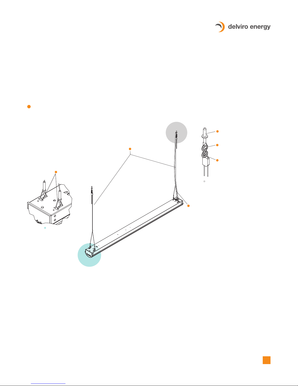
3. Run the straight wire of the aircraft cable through the adaptor which will form a loop, and adjust as per height requirement.
Once fixture is leveled, cut the excess wires. Attach an S-Hook to the loop formed and use pliers to 'close' off the ends of the
S-Hook (minimum S-Hook size 1.625" long, 0.135" thick with 0.5" ID in steel). There should be a loop at the end of this cable
at the top after inserting cable into fastener which can be attached to an S-Hook.
Follow the Electrical Codes of the Country where this fixture will be installed. For Canada follow the Canadian
Electrical Code (CE) and for the United States follow the National Electrical Code (NEC). Failure to follow these
instructions could result in electric shock or damage property. All wiring should also be performed by a qualified
electrician. Check with local electrical authority for installation compliance regulations. Due to variations in roofing
materials use these installation instructions as a guideline only.
NOTE:
Aircraft Cable
4. At the top of the S-Hook, attach an eye lag screw. The installer should choose the proper eye lag screw as there are different
types used for wood, steel and concrete. Minimum eye lag screw should be #12 size.
ZIP LIGHT
INSTALLATION INSTRUCTIONS
B
E
Optional Aircraft Cable (QTY: 2)
A
Hooks Engaged with Slot
A
B
Eye Lag Screw
Wire can be tie wrapped to Aircraft Cable but
also has to have an independent support at
the ceiling
S-Hook
Loop Optional Aircraft Cable
through fasteners and adjust
accordingly

2
info@delviro.com | 1.877.502.3434www.delviro.com 1
5. Pull the existing wire from the Zip Light fixture into the junction box. Use a strain relief on the access plate if required. Connect
the appropriate wires using wire nuts (Black to Black, White to White and Green to Ground wire). Ensure the ground wire is also
grounded to the junction box using a ground screw. The wire from the Zip Light fixture can be tie wrapped to the aircraft cable
but also has to be independently supported to the ceiling or roof. Check to see if the Zip Light fixture is securely in place and that
the Aircraft Cable is properly attached to the ceiling and the fixture.
6. Ensure Zip Light fixture is connected to a timer, relay system, motion detector or switch so that it can be activated easily.
7. Check all connections for open loops and replace loose or damaged wires if necessary.
8. Turn the electrical power on from the electrical power.
9. Test the connection by turning on the timer, relay system, motion detector or light switch that the Zip Light fixture is connected to.
ZIP LIGHT
INSTALLATION INSTRUCTIONS

3
info@delviro.com | 1.877.502.3434www.delviro.com 1
ZIP LIGHT
INSTALLATION INSTRUCTIONS
Chain Mount
1. Disconnect the electrical power on the electrical panel prior to installing the Zip Light fixture.
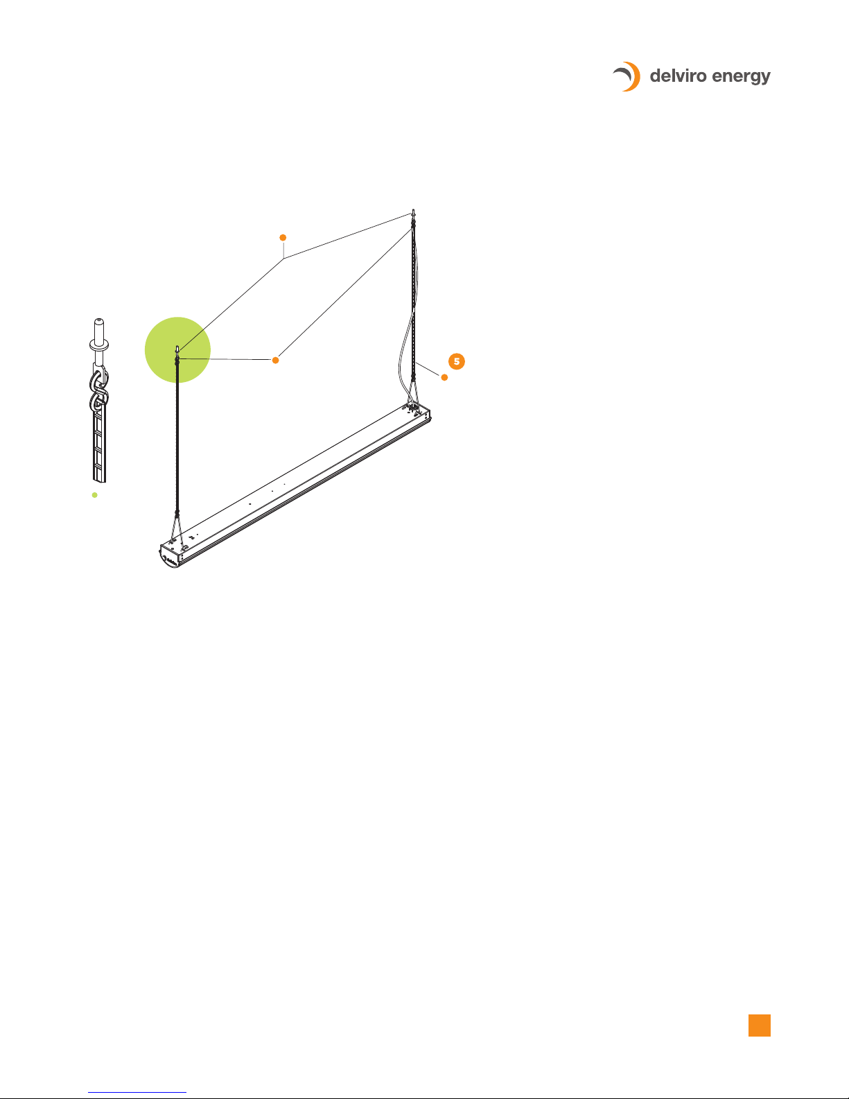
2. The Zip Light fixture is shipped with 2 Caddy Clips (V-Hooks), one at each end of the fixture. Ensure that the Caddy Clips are
oriented as per image 2. Use pliers to close off end such that the clips cannot be removed.
3. Attach an S-Hook to the top of the Caddy Clip and then attach the other side of the S-Hook to Jack Chain (minimum #10 size).
Use pliers to ‘close’ off the ends of the S-Hook onto the Caddy Clip and Jack Chain (minimum S-Hook size 1.625" long, 0.135"
thick with 0.5" ID in steel).
A
Caddy Clips (Quantity: 2)
AA
Jack Chains
S-Hooks (Quantity: 2)
B
B
B
4
info@delviro.com | 1.877.502.3434www.delviro.com 1
ZIP LIGHT
INSTALLATION INSTRUCTIONS
4. At the top of the Jack Chain attach an S-Hook to the Jack Chain and the other end of the Jack Chain to an eye lag screw.
The installer should choose the proper eye lag screw as there are different types used for wood, steel and concrete.
Minimum eye lag screw should be #12 size.
5. Pull the existing wire from the Zip Light fixture into the junction box. Use a strain relief on the access plate if required.
Connect the appropriate wires using wire nuts (Black to Black, White to White and Green to Ground wire). Ensure the
ground wire is also grounded to the junction box using a ground screw. The wire from the Zip Light fixture can be tied
wrapped to the jack chain but also has to be independently supported to the ceiling or roof. Check to see if the Zip Light
fixture is securely in place and that the jack chain is properly attached to the ceiling and the fixture.
6. Ensure the Zip Light fixture is connected to a timer, relay system, motion detector or switch so that it can be activated easily.
7. Check all connections for open loops and replace loose or damaged wires if necessary.
8. Turn the electrical power on from the electrical panel.
9. Test the connection by turning on the timer, relay system, motion detector or light switch that the Zip Light fixture is connected to.
Eye-Lag Screws (Quantity: 2)
C
S-Hooks (Quantity: 2)
AA
C
Wire can be tie wrapped to pipe but also has to have
an independent support at the ceiling
Table of contents
Other delviro energy Lantern manuals

Popular Lantern manuals by other brands


shada
shada 1000436 instruction manual

BEGA
BEGA 84 036 Instructions for use

BEGA
BEGA 33 596 Instructions for use

Dale Tiffany
Dale Tiffany GT701162 Assembly instructions

Wagan
Wagan Brite Nite Pop-Up USB Lantern user manual

Eaton
Eaton Crouse-Hinds Pauluhn DLLA M2 Series Installation & maintenance information